2005 SUZUKI SWIFT Arm
[x] Cancel search: ArmPage 290 of 1496

Downloaded from www.Manualslib.com manuals search engine 1D-5 Engine Mechanical:
11) Connect negative cable at battery.
12) Install special tools (Compression gauge) into spark plug hole.
Special tool
(A): 09915–64512
(B): 09915–64530
(C): 09915–67010
13) Disengage clutch (1) (to lighten starting load on engine) for M/T vehicle, and depress accelerator
pedal (2) all the way to make throttle fully open.
14) Crank engine with fully charged battery, and read the highest pressure on compression gauge.
NOTE
• For measuring compression pressure, crank engine at least 250 r/min. by using
fully charged battery.
• If measured compression pressure is lower than limit value, check installation
condition of special tool. If it is properly
installed, possibility is compression
pressure leakage from where piston ring
and valve contact.
Compression pressure
Standard: 1400 kPa (14.0 kg/cm2, 199.0 psi)
Limit: 1100 kPa (11.0 kg/cm2, 156.0 psi)
Max. difference between any two cylinders: 100
kPa (1.0 kg/cm
2, 14.2 psi) 15) Carry out Steps 12) through 14) on each cylinder to
obtain 4 readings.
16) Disconnect negative cable at battery.
17) After checking, install spark plugs and ignition coil assemblies (2) with high-tension cord (3).
18) Connect ignition coil couplers (1).
19) Connect fuel injector wires (4) at the coupler.
20) Install cylinder head upper cover.
21) Install air cleaner assembly and air suction hose referring to “Air Cleaner Components”.
22) Install engine cover.
23) Connect negative cable at battery.
Engine Vacuum CheckS7RS0B1404002
The engine vacuum that develops in the intake line is a
good indicator of the condition of the engine. The
vacuum checking procedure is as follows:
1) Warm up engine to normal operating temperature.
NOTE
After warming up engine, be sure to place
transaxle gear shift lever in “Neutral”, and set
parking brake and block drive wheels.
2) Stop engine and turn off the all electric switches.
3) Remove engine cover.
4) Remove air cleaner assembly and air suction hose referring to “Air Cleaner Components”.
5) Remove PCV hose (1) from PCV valve (2).
(A)
(C)
(B)
I3RH0B140009-01
I2RH0B140005-01
I2RH0B140003-01
2
1
I6RS0B141001-01
Page 355 of 1496

Downloaded from www.Manualslib.com manuals search engine Engine Lubrication System: 1E-3
6) Start engine and warm engine up to normal operating temperature.
NOTE
Be sure to shift transaxle gear shift lever in
“Neutral” (shift select lever in “P” range for
A/T vehicle), set parking brake and block
drive wheels.
7) After warming up, raise engine speed to 4,000 r/min. and measure oil pressure.
Oil pressure specification
More than 270 kPa (2.7 kg/cm2, 39.8 psi) at 4,000
r/min. (rpm)
8) After checking oil pressure, stop engine and remove oil pressure gauge and attachment.
9) Before reinstalling oil pressure switch (2), be sure to
wrap its screw threads with sealing tape (1) and
tighten switch to specified torque.
NOTE
If sealing tape edge is bulged out from screw
threads of switch, cut it off.
Tightening torque
Oil pressure switch (a): 13 N·m (1.3 kgf-m, 9.5
lb-ft) 10) Start engine and check oil pressure switch for oil
leakage. If oil leakage is found, repair it.
11) Connect oil pressure switch coupler (1).
Repair Instructions
Heat Exchanger ComponentsS7RS0B1506001
I2RH0B150005-01
I2RH0B150006-01
3
4
5
7
6
(a)
2
1
I6RS0B151001-02
1. Heat exchanger inlet No. 1 hose 4. Gasket7. O-ring
: Apply engine oil.
2. Heat exchanger outlet No. 1 hose 5. Heat exchanger stand bolt : 22 N⋅m (2.2 kgf-m, 16.0 lb-ft)
3. Heat exchanger 6. Oil filter adapter case : Do not reuse.
Page 365 of 1496

Downloaded from www.Manualslib.com manuals search engine Engine Cooling System: 1F-2
Coolant capacity
For M/T model:• Engine, radiator and heater: 5.5 liters (11.62/9.68 US/lmp pt.)
• Reservoir: 0.7 liters (1.48/1.23 US/lmp pt.)
• Total: 6.2 liters (13.10/10.91 US/lmp pt.)
For A/T model: • Engine, radiator and heater: 5.4 liters (11.41/9.50 US/lmp pt.)
• Reservoir: 0.7 liters (1.48/1.23 US/lmp pt.)
• Total: 6.1 liters (12.89/10.74 US/lmp pt.)
Schematic and Routing Diagram
Coolant CirculationS7RS0B1602001
While the engine is warmed up (thermosta t closed), coolant circulates as follows.
11
10 3 7
4
9
8
6
5
2 12 1
13
I6RS0C160001-01
1. Radiator inlet hose
6. Water pump11. Heater core
2. Radiator outlet hose 7. Throttle body12. Radiator
3. Throttle body inlet hose 8. Engine13. Heat exchanger
4. Throttle body outlet hose 9. Heater core inlet hose
5. Thermostat 10. Heater core outlet hose
Page 366 of 1496

Downloaded from www.Manualslib.com manuals search engine 1F-3 Engine Cooling System:
When coolant is warmed up to normal temperature and the thermostat opens, coolant passes through the radiator
core to be cooled as follows.
11
10 3 7
4
9
8
6
5
2 12 1
13
I6RS0C160002-01
1. Radiator inlet hose
6. Water pump11. Heater core
2. Radiator outlet hose 7. Throttle body12. Radiator
3. Throttle body inlet hose 8. Engine13. Heat exchanger
4. Throttle body outlet hose 9. Heater core inlet hose
5. Thermostat 10. Heater core outlet hose
Page 369 of 1496

Downloaded from www.Manualslib.com manuals search engine Engine Cooling System: 1F-6
Coolant Level CheckS7RS0B1606002
WARNING!
To help avoid danger of being burned, do not
remove radiator cap while engine and
radiator are still hot. Scalding fluid and steam
can be blown out under pressure if radiator
cap is taken off too soon.
To check level, lift hood and look at “see-through”
coolant reservoir.
It is not necessary to remove radiator cap to check
coolant level.
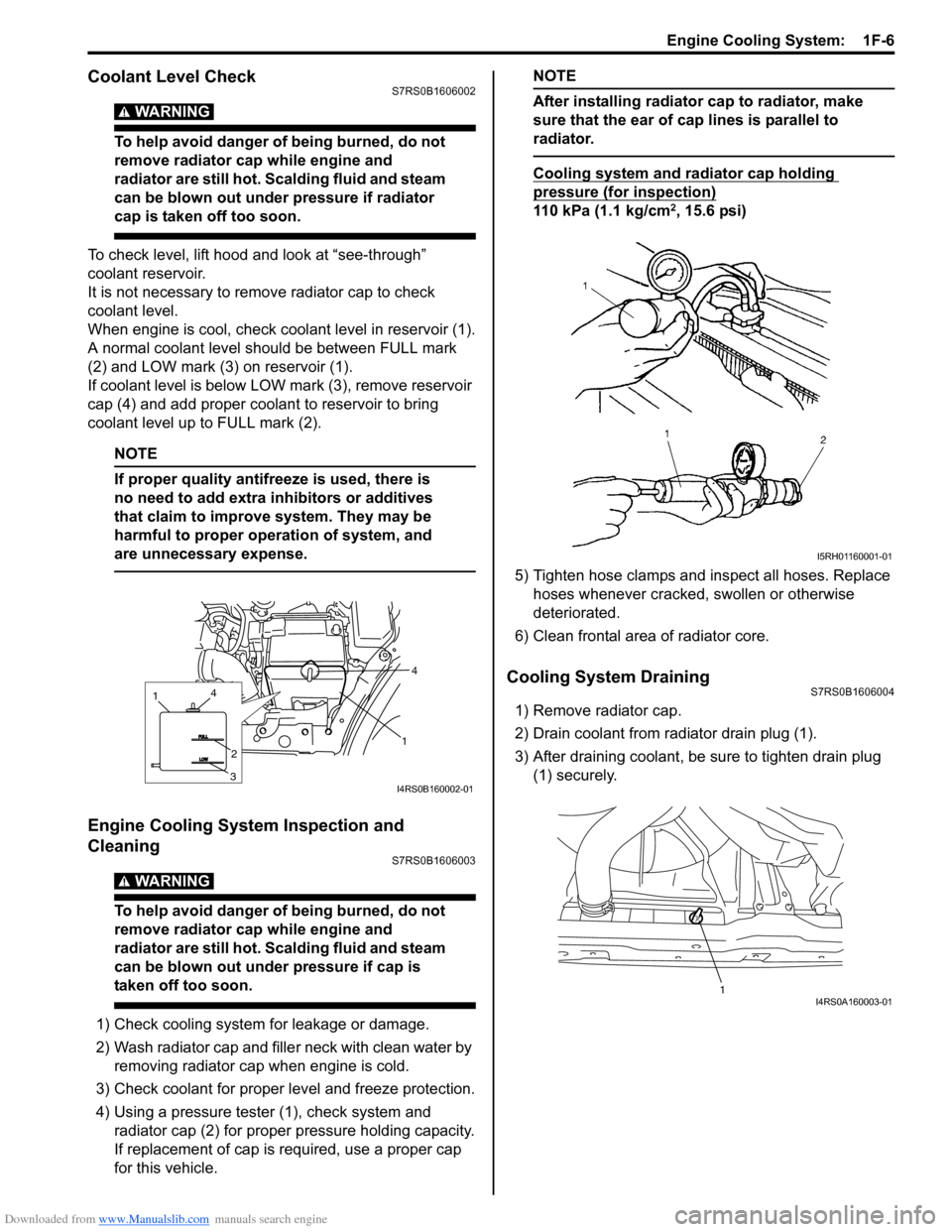
When engine is cool, check coolant level in reservoir (1).
A normal coolant level should be between FULL mark
(2) and LOW mark (3) on reservoir (1).
If coolant level is below LOW mark (3), remove reservoir
cap (4) and add proper coolant to reservoir to bring
coolant level up to FULL mark (2).
NOTE
If proper quality antifreeze is used, there is
no need to add extra inhibitors or additives
that claim to improve system. They may be
harmful to proper operation of system, and
are unnecessary expense.
Engine Cooling System Inspection and
Cleaning
S7RS0B1606003
WARNING!
To help avoid danger of being burned, do not
remove radiator cap while engine and
radiator are still hot. Scalding fluid and steam
can be blown out under pressure if cap is
taken off too soon.
1) Check cooling system for leakage or damage.
2) Wash radiator cap and fille r neck with clean water by
removing radiator cap when engine is cold.
3) Check coolant for proper level and freeze protection.
4) Using a pressure tester (1), check system and radiator cap (2) for proper pressure holding capacity.
If replacement of cap is required, use a proper cap
for this vehicle.
NOTE
After installing radiator cap to radiator, make
sure that the ear of cap lines is parallel to
radiator.
Cooling system and radiator cap holding
pressure (for inspection)
110 kPa (1.1 kg/cm2, 15.6 psi)
5) Tighten hose clamps and inspect all hoses. Replace hoses whenever cracked, swollen or otherwise
deteriorated.
6) Clean frontal area of radiator core.
Cooling System DrainingS7RS0B1606004
1) Remove radiator cap.
2) Drain coolant from radiator drain plug (1).
3) After draining coolant, be sure to tighten drain plug (1) securely.
1
4
1
3
2
4
I4RS0B160002-01
I5RH01160001-01
1I4RS0A160003-01
Page 378 of 1496

Downloaded from www.Manualslib.com manuals search engine 1G-3 Fuel System:
4) Check that battery voltage is 11 V or more.
5) Measure fuel pressure at each condition.If measured pressure is out of specification, refer to
“Fuel Pressure Check in Section 1A” and check each
possibly defective part. Replace if found defective.
a) Turn ignition switch ON to operate fuel pump and after 2 seconds turn it OFF. Repeat this 3 or 4
times and then check fuel pressure.
Fuel pressure specification
With fuel pump operating and engine
stopped: 270 – 310 kPa (2.7 – 3.1 kg/cm2, 38.4
– 44.0 psi)
b) Start engine and warm it up to normal operating temperature, and measure fuel pressure at
idling.
Fuel pressure specification
At specified idle speed: 270 – 310 kPa (2.7 –
3.1 kg/cm2, 38.4 – 44.0 psi)
c) Stop engine, and measure fuel pressure at one minute after stopping.
Fuel pressure specification
With 1 min. after engine (fuel pump) stop
(Pressure reduces as time passes): Over 300
kPa (3.0 kg/cm
2, 42.7 psi)
6) After checking fuel pressure, remove fuel pressure gauge.
WARNING!
As fuel feed line is still under high fuel
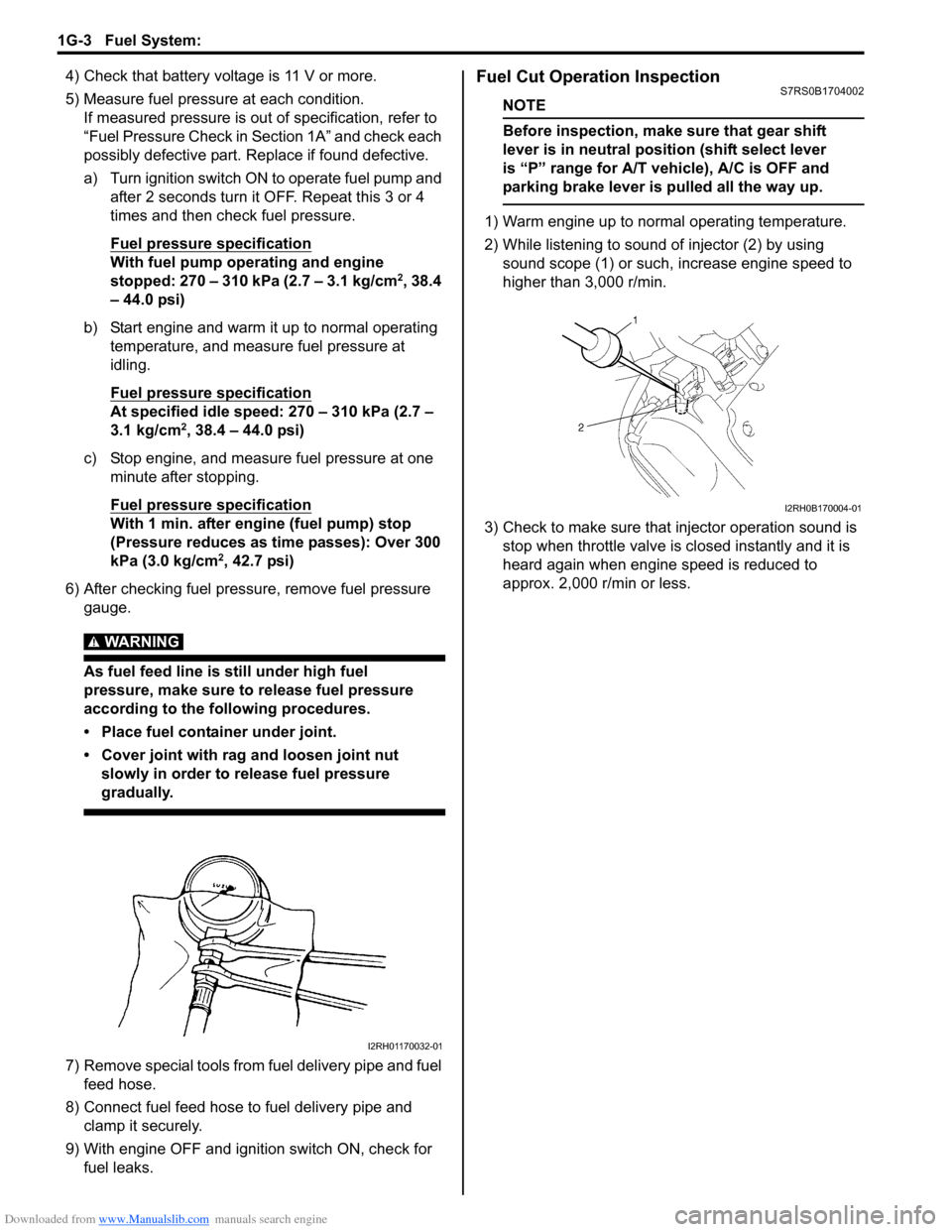
pressure, make sure to release fuel pressure
according to the following procedures.
• Place fuel container under joint.
• Cover joint with rag and loosen joint nut slowly in order to release fuel pressure
gradually.
7) Remove special tools from fuel delivery pipe and fuel feed hose.
8) Connect fuel feed hose to fuel delivery pipe and clamp it securely.
9) With engine OFF and ignition switch ON, check for fuel leaks.
Fuel Cut Operation InspectionS7RS0B1704002
NOTE
Before inspection, make sure that gear shift
lever is in neutral positi on (shift select lever
is “P” range for A/T vehicle), A/C is OFF and
parking brake lever is pulled all the way up.
1) Warm engine up to normal operating temperature.
2) While listening to sound of injector (2) by using sound scope (1) or such, increase engine speed to
higher than 3,000 r/min.
3) Check to make sure that injector operation sound is stop when throttle valve is closed instantly and it is
heard again when engine speed is reduced to
approx. 2,000 r/min or less.
I2RH01170032-01
I2RH0B170004-01
Page 389 of 1496

Downloaded from www.Manualslib.com manuals search engine Fuel System: 1G-14
Fuel Tank Purging ProcedureS7RS0B1706015
WARNING!
• Before starting the following procedure, be sure to observe “Precautions on Fuel
System Service” in order to reduce the risk
or fire and personal injury.
• This purging procedure will not remove all fuel vapor.
Do not attempt any repair on tank using
heat of flame as an explosion resulting in
personal injury could occur.
CAUTION!
Never remain water in fu el tank after washing,
or fuel tank inside will get corrosion.
The following procedure are used for purging fuel tank.
1) After removing fuel tank, remove all hoses, pipes and fuel pump assembly from fuel tank.
2) Drain all remaining fuel from tank.
3) Place fuel tank to flushing area.
4) Fill tank with warm water or tap water, and agitate
vigorously and drain. Repeat this washing until
inside of tank is clean. Replace tank if its inside is
rusty.
5) Completely flush out rema ining water after washing.
Fuel Pump On-Vehicle InspectionS7RS0B1706016
WARNING!
Before starting the following procedure, be
sure to observe “Precautions on Fuel System
Service” in order to reduce the risk or fire
and personal injury.
NOTE
The fuel pressure regulator is incorporated
with the fuel pump assembly so individual
inspection of it is impossible.
1) Remove filler cap and turn ON ignition switch (2).
Then fuel pump operating sound should be heard
from fuel filler (1) for about 2 seconds and stop. Be
sure to reinstall fuel filler cap after checking.
If the check result is not satisfactory, go to “Fuel
Pump and Its Circuit Check in Section 1A”. 2) Turn OFF ignition switch and leave over 10 minutes
as it is.
3) Fuel pressure should be felt at fuel feed hose (1) for about 2 seconds after ignition switch ON.
If fuel pressure is not felt, go to “Fuel Pressure
Check in Section 1A”.
Fuel Pump Assembly Removal and InstallationS7RS0B1706017
WARNING!
Before starting the following procedure, be
sure to observe “Precautions on Fuel System
Service” in order to reduce the risk or fire
and personal injury.
Removal
1) Remove fuel tank from vehicle. Refer to “Fuel Tank Removal and Installation”.
2) Disconnect fuel feed pipe (1) from fuel pump assembly (2) referring to “Fuel Hose Disconnecting
and Reconnecting”.
IVSY01170013-01
1I3RM0A170019-01
1
2
I6RS0C170008-02
Page 390 of 1496

Downloaded from www.Manualslib.com manuals search engine 1G-15 Fuel System:
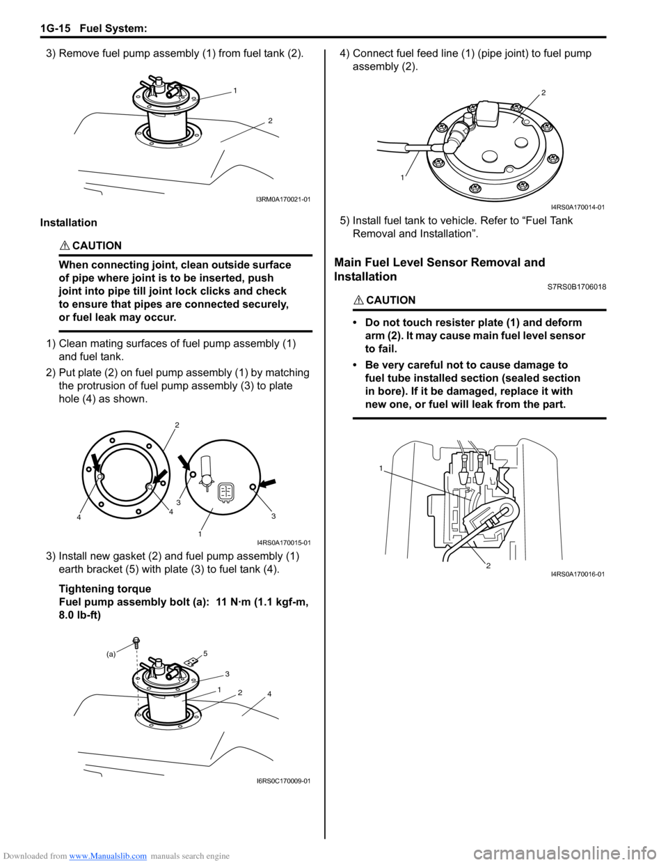
3) Remove fuel pump assembly (1) from fuel tank (2).
Installation
CAUTION!
When connecting joint, clean outside surface
of pipe where joint is to be inserted, push
joint into pipe till jo int lock clicks and check
to ensure that pipes are connected securely,
or fuel leak may occur.
1) Clean mating surfaces of fuel pump assembly (1) and fuel tank.
2) Put plate (2) on fuel pump assembly (1) by matching the protrusion of fuel pump assembly (3) to plate
hole (4) as shown.
3) Install new gasket (2) and fuel pump assembly (1) earth bracket (5) with plate (3) to fuel tank (4).
Tightening torque
Fuel pump assembly bolt (a): 11 N·m (1.1 kgf-m,
8.0 lb-ft) 4) Connect fuel feed line (1) (pipe joint) to fuel pump
assembly (2).
5) Install fuel tank to vehi cle. Refer to “Fuel Tank
Removal and Installation”.
Main Fuel Level Sensor Removal and
Installation
S7RS0B1706018
CAUTION!
• Do not touch resister plate (1) and deform arm (2). It may cause main fuel level sensor
to fail.
• Be very careful not to cause damage to fuel tube installed section (sealed section
in bore). If it be damaged, replace it with
new one, or fuel will leak from the part.
1
2
I3RM0A170021-01
3
1
3
2
44
I4RS0A170015-01
3
1 2
(a)
4
5
I6RS0C170009-01
2
1
I4RS0A170014-01
1
2I4RS0A170016-01