2005 SUZUKI SWIFT Arm
[x] Cancel search: ArmPage 457 of 1496
Downloaded from www.Manualslib.com manuals search engine Rear Suspension: 2C-3
2) Remove floor jack (2) from rear axle.
3) Install rear wheels and tighten wheel nuts specified torque.
Tightening torque
Wheel nut: 85 N·m (8.5 kgf-m, 61.5 lb-ft)
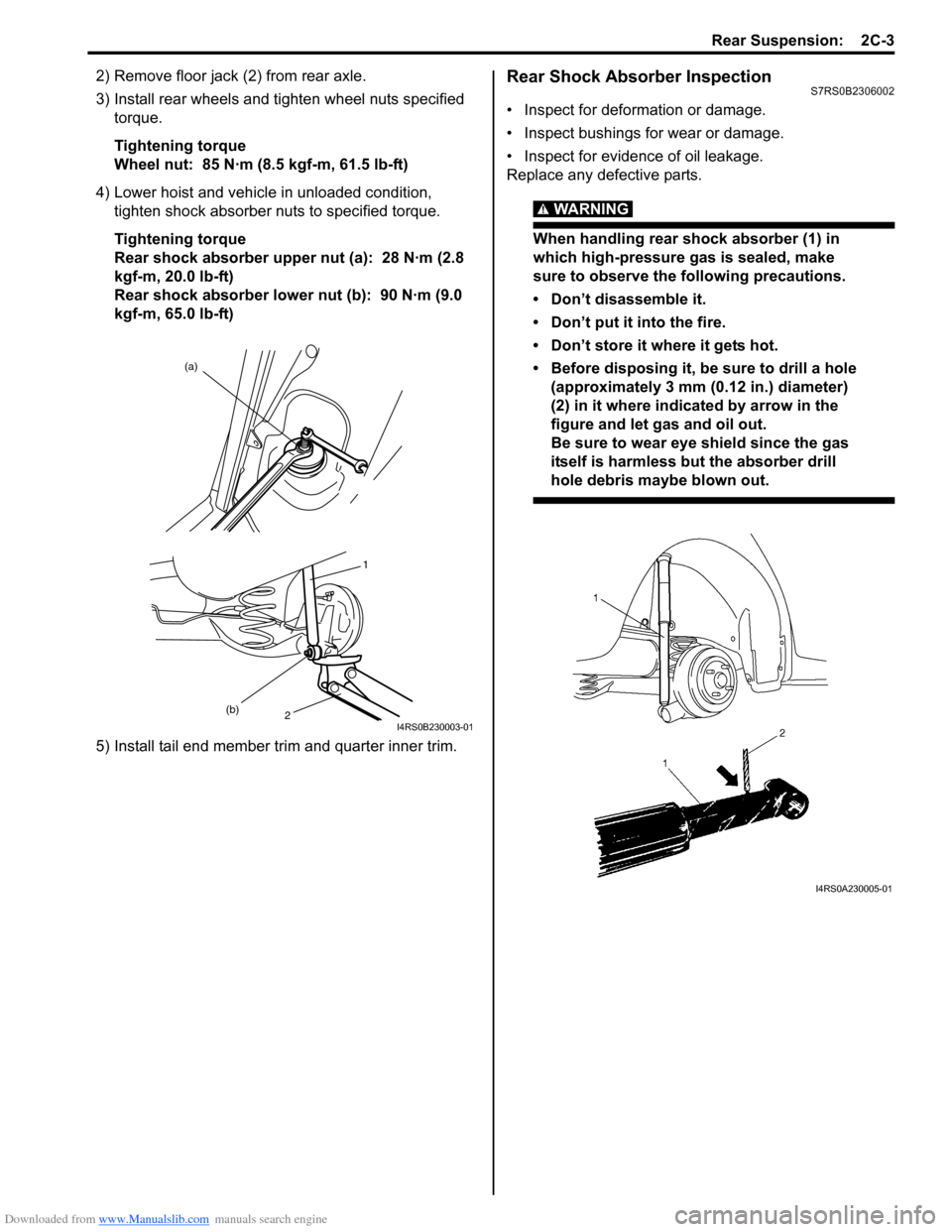
4) Lower hoist and vehicle in unloaded condition, tighten shock absorber nuts to specified torque.
Tightening torque
Rear shock absorber upper nut (a): 28 N·m (2.8
kgf-m, 20.0 lb-ft)
Rear shock absorber lower nut (b): 90 N·m (9.0
kgf-m, 65.0 lb-ft)
5) Install tail end member trim and quarter inner trim.Rear Shock Absorber InspectionS7RS0B2306002
• Inspect for deformation or damage.
• Inspect bushings for wear or damage.
• Inspect for evidence of oil leakage.
Replace any defective parts.
WARNING!
When handling rear shock absorber (1) in
which high-pressure gas is sealed, make
sure to observe the following precautions.
• Don’t disassemble it.
• Don’t put it into the fire.
• Don’t store it where it gets hot.
• Before disposing it, be sure to drill a hole (approximately 3 mm (0.12 in.) diameter)
(2) in it where indicated by arrow in the
figure and let gas and oil out.
Be sure to wear eye shield since the gas
itself is harmless but the absorber drill
hole debris maybe blown out.
(a)
1
(b) 2
I4RS0B230003-01
I4RS0A230005-01
Page 461 of 1496
Downloaded from www.Manualslib.com manuals search engine Rear Suspension: 2C-7
3) Remove rear brake caliper assemblies (right & left)
and brake discs (right & left ). For details, refer to
Step 2) to 3) of “Removal” under “Rear Brake Disc
Removal and Installa tion in Section 4C”.
4) Remove rear wheel hubs (r ight & left). For details,
refer to Step 3) to 5) of “Removal” under “Rear
Wheel Hub Removal and Installation”.
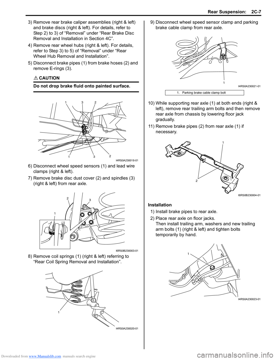
5) Disconnect brake pipes (1) from brake hoses (2) and remove E-rings (3).
CAUTION!
Do not drop brake fluid onto painted surface.
6) Disconnect wheel speed sensors (1) and lead wire clamps (right & left).
7) Remove brake disc dust cover (2) and spindles (3) (right & left) from rear axle.
8) Remove coil springs (1) (right & left) referring to “Rear Coil Spring Removal and Installation”. 9) Disconnect wheel speed sensor clamp and parking
brake cable clamp from rear axle.
10) While supporting rear axle (1) at both ends (right & left), remove rear trailing arm bolts and then remove
rear axle from chassis by lowering floor jack
gradually.
11) Remove brake pipes (2) from rear axle (1) if necessary.
Installation 1) Install brake pipes to rear axle.
2) Place rear axle on floor jacks. Then install trailing arm, washers and new trailing
arm bolts (1) (right & left) and tighten bolts
temporarily by hand.
1
1
2
2
3
3I4RS0A230018-01
1
2
3
I6RS0B230003-01
1
I4RS0A230020-01
1. Parking brake cable clamp bolt
1I4RS0A230021-01
2
1
I6RS0B230004-01
1
I4RS0A230023-01
Page 463 of 1496
Downloaded from www.Manualslib.com manuals search engine Rear Suspension: 2C-9
12) Fill reservoir with brake fluid and bleed brake system. For bleeding operation, see “Air Bleeding of
Brake System in Section 4A”.
13) Install wheel and tighten wheel nuts to specified torque.
Tightening torque
Wheel nut: 85 N·m (8.5 kgf-m, 61.5 lb-ft)
14) Adjust parking brake cable. For adjustment, refer to “Parking Brake Inspection and Adjustment in Section
4D”.
15) Lower hoist and bounce vehicle up and down several times to stabilize suspension.
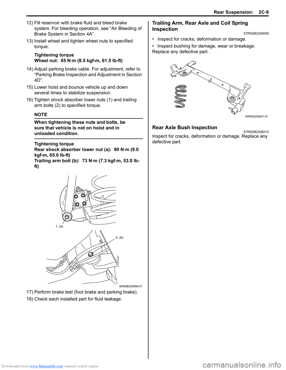
16) Tighten shock ab sorber lower nuts (1) and trailing
arm bolts (2) to specified torque.
NOTE
When tightening these nuts and bolts, be
sure that vehicle is not on hoist and in
unloaded condition.
Tightening torque
Rear shock absorber lower nut (a): 90 N·m (9.0
kgf-m, 65.0 lb-ft)
Trailing arm bolt (b): 73 N·m (7.3 kgf-m, 53.0 lb-
ft)
17) Perform brake test (foot brake and parking brake).
18) Check each installed part for fluid leakage.
Trailing Arm, Rear Axle and Coil Spring
Inspection
S7RS0B2306009
• Inspect for cracks, deformation or damage.
• Inspect bushing for damage, wear or breakage.
Replace any defective part.
Rear Axle Bush InspectionS7RS0B2306010
Inspect for cracks, deformation or damage. Replace any
defective part.
1, (a)
2, (b)
I6RS0B230008-01
I4RS0A230031-01
Page 467 of 1496
Downloaded from www.Manualslib.com manuals search engine Rear Suspension: 2C-13
Spindle InspectionS7RS0B2306015
• Inspect for cracks, deformation or damage.Replace any defective part.
Rear Suspension Fasteners InspectionS7RS0B2306016
Check each bolt and nut fastening suspension parts for
tightness. Tighten loose one, if any, to specified torque
referring to the figure in “Rear Suspension Construction”.
Specifications
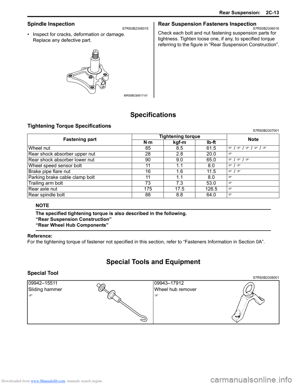
Tightening Torque SpecificationsS7RS0B2307001
NOTE
The specified tightening torque is also described in the following.
“Rear Suspension Construction”
“Rear Wheel Hub Components”
Reference:
For the tightening torque of fastener not specified in this section, refer to “Fasteners Information in Section 0A”.
Special Tools and Equipment
Special ToolS7RS0B2308001
I6RS0B230017-01
Fastening part Tightening torque
Note
N ⋅mkgf-mlb-ft
Wheel nut 85 8.5 61.5 �) / �) / �) / �) / �)
Rear shock absorber upper nut 28 2.8 20.0 �)
Rear shock absorber lower nut 90 9.0 65.0 �) / �) / �)
Wheel speed sensor bolt 11 1.1 8.0 �) / �)
Brake pipe flare nut 16 1.6 11.5 �) / �)
Parking brake cable clamp bolt 11 1.1 8.0 �)
Trailing arm bolt 73 7.3 53.0 �)
Rear axle nut 175 17.5 126.5 �)
Rear spindle bolt 88 8.8 64.0 �)
09942–1551109943–17912
Sliding hammer Wheel hub remover
�)�)
Page 468 of 1496
Downloaded from www.Manualslib.com manuals search engine 2D-1 Wheels and Tires:
Suspension
Wheels and Tires
Precautions
Precaution for Emergency Flat Tire Repair KitS7RS0B2400001
WARNING!
Flat tire repair sealant including in kit is
harmful. Be sure to observe the following.
Otherwise, your health may be ruined.
• If swallowed, get medical attention immediately.
• Keep out of reach of children.
• Select place where there is good ventilation for this work.
• If it enters eye or contacts skin, wash thoroughly with water. If anything
abnormal still rema ins, get medical
attention immediately.
• Do not discard tire containing sealant as it is. Make sure to remove sealant from tire,
referring to “Tire Repair for Emergency
Repaired-Tire with Sealant”.
• Dispose of sealant as waste oil.
CAUTION!
• When tire repaired with Emergency Flat Tire Repair Kit is brought in, remove flat
tire repair sealant from tire and repair flat
tire referring to “Tire Repair for Emergency
Repaired-Tire with Sealant”.
• Sealant expiration date is printed on bottle label. if it expires, sealant should be
replaced with a new one to ensure
emergency flat tire repair.
General Description
Tires DescriptionS7RS0B2401001
The tire is of tubeless type. The tire is designed to
operate satisfactorily with loads up to the full rated load
capacity when inflated to the recommended inflation
pressures.
Correct tire pressures and driving habits have an
important influence on tire life. Heavy cornering,
excessively rapid acceleration, and unnecessary sharp
braking increase tire wear.
Tire Placard
The “Tire Placard” is located on the left or right door lock
pillar and should be referred to tire information.
The placard lists the maximum load, tire size and cold
tire pressure where applicable.
NOTE
Whether rim size and/or maximum load are
listed or not depends on regulations of each
country.
Inflation of Tires
The pressure recommended for any model is carefully
calculated to give a satisfacto ry ride, stability, steering,
tread wear, tire life and resistance to bruises.
Tire pressure, with tires cold, (after vehicle has set for 3
hours or more, or driven less than one mile) should be
checked monthly or before any extended trip. Set to the
specifications on the “Tire Placard” located on the left
door lock pillar.
It is normal for tire pressure to increase when the tires
become hot during driving.
Do not bleed or reduce tire pressure after driving.
Bleeding reduces the “Cold Inflation Pressure”.
Higher than recommended pressure can cause:
• Hard ride
• Tire bruising or carcass damage
• Rapid tread wear at center of tire
Unequal pressure on same axle can cause:
• Uneven braking
• Steering lead
• Reduced handling
• Swerve on acceleration
Page 482 of 1496
Downloaded from www.Manualslib.com manuals search engine 3A-4 Drive Shaft / Axle:
Front Drive Shaft Assembly On-Vehicle
Inspection
S7RS0B3106002
• Check boots for breakage or deterioration.
• Check wheel side joint for rattle or smooth rotation.
• Check differential side (or center shaft side) joint for smooth rotation.
If any abnormality is found, replace.
Front Drive Shaft Assembly Removal and
Installation
S7RS0B3106003
Removal
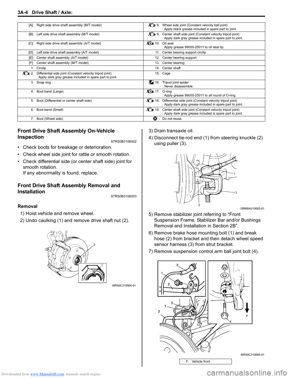
1) Hoist vehicle and remove wheel.
2) Undo caulking (1) and remove drive shaft nut (2). 3) Drain transaxle oil.
4) Disconnect tie-rod end (1) from steering knuckle (2)
using puller (3).
5) Remove stabilizer join t referring to “Front
Suspension Frame, Stabiliz er Bar and/or Bushings
Removal and Installati on in Section 2B”.
6) Remove brake hose mounting bolt (1) and break hose (2) from bracket and then detach wheel speed
sensor harness (3) from strut bracket.
7) Remove suspension contro l arm ball joint bolt (4).
[A]: Right side drive shaft assembly (M/T model) 8. Wheel side joint (Constant velocity ball joint)
: Apply black grease included in spare part to joint.
[B]: Left side drive shaft assembly (M/T model) 9. Center shaft side joint (Constant velocity tripod joint)
: Apply dark gray grease included in spare part to joint.
[C]: Right side drive shaft assembly (A/T model) 10. Oil seal
: Apply grease 99000-25011 to oil seal lip.
[D]: Left side drive shaft assembly (A/T model) 11. Center bearing support circlip
[E]: Center shaft assembly (A/T model) 12. Center bearing support
[F]: Center shaft assembly (M/T model) 13. Center bearing
1. Circlip 14. Center shaft
2. Differential side joint (Constant velocity tripod joint) : Apply dark gray grease included in spare part to joint. 15. Cage
3. Snap ring 16. Tripod joint spider
: Never disassemble.
4. Boot band (Large) 17. O-ring
: Apply grease 99000-25011 to all round of O-ring.
5. Boot (Differential or center shaft side) 18. Differential side joint (Constant velocity tripod joint)
: Apply dark gray grease included in spare part to joint.
6. Boot band (Small) 19. Center shaft side joint (Constant velocity tripod joint)
: Apply dark gray grease included is spare part to joint.
7. Boot (Wheel side) : Do not reuse.
I6RS0C310004-01
F: Vehicle front
I3RM0A310003-01
I6RS0C310005-01
Page 483 of 1496
Downloaded from www.Manualslib.com manuals search engine Drive Shaft / Axle: 3A-5
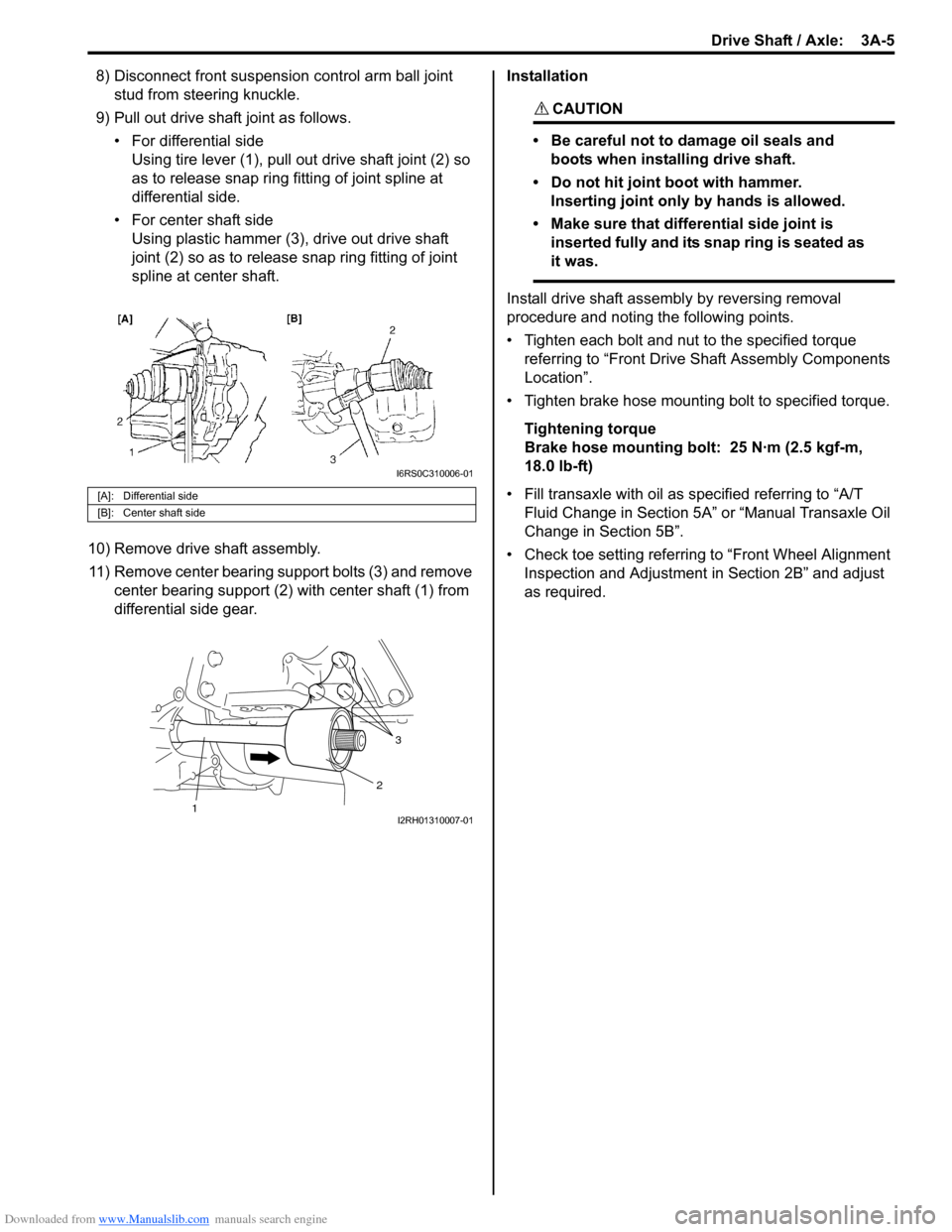
8) Disconnect front suspension control arm ball joint
stud from steering knuckle.
9) Pull out drive shaft joint as follows. • For differential sideUsing tire lever (1), pull out drive shaft joint (2) so
as to release snap ring fitting of joint spline at
differential side.
• For center shaft side Using plastic hammer (3), drive out drive shaft
joint (2) so as to release snap ring fitting of joint
spline at center shaft.
10) Remove drive shaft assembly. 11) Remove center bearing support bolts (3) and remove center bearing support (2) with center shaft (1) from
differential side gear. Installation
CAUTION!
• Be careful not to damage oil seals and
boots when installing drive shaft.
• Do not hit joint boot with hammer. Inserting joint only by hands is allowed.
• Make sure that differential side joint is inserted fully and its snap ring is seated as
it was.
Install drive shaft assemb ly by reversing removal
procedure and noting the following points.
• Tighten each bolt and nut to the specified torque referring to “Front Drive Shaft Assembly Components
Location”.
• Tighten brake hose mounting bolt to specified torque.
Tightening torque
Brake hose mounting bolt: 25 N·m (2.5 kgf-m,
18.0 lb-ft)
• Fill transaxle with oil as sp ecified referring to “A/T
Fluid Change in Section 5A” or “Manual Transaxle Oil
Change in Section 5B”.
• Check toe setting referring to “Front Wheel Alignment Inspection and Adjustment in Section 2B” and adjust
as required.
[A]: Differential side
[B]: Center shaft side
I6RS0C310006-01
3
2
1I2RH01310007-01
Page 484 of 1496
Downloaded from www.Manualslib.com manuals search engine 3A-6 Drive Shaft / Axle:
Front Drive Shaft Disassembly and ReassemblyS7RS0B3106004
Disassembly
Tripod joint
CAUTION!
• Disassembly of wheel side joint is not allowed. If any noise or damage exists in it,
replace it as assembly.
• Do not disassemble tripod joint spider. If any malcondition is found in it, replace it
as differential side joint assembly.
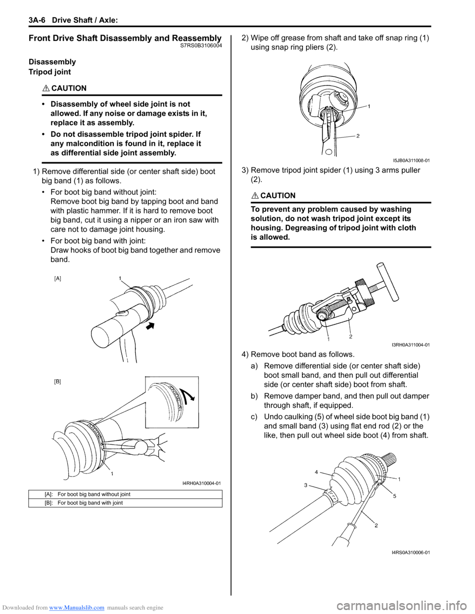
1) Remove differential side (or center shaft side) boot
big band (1) as follows.
• For boot big band without joint:Remove boot big band by tapping boot and band
with plastic hammer. If it is hard to remove boot
big band, cut it using a nipper or an iron saw with
care not to damage joint housing.
• For boot big band with joint: Draw hooks of boot big band together and remove
band. 2) Wipe off grease from shaft and take off snap ring (1)
using snap ring pliers (2).
3) Remove tripod joint spid er (1) using 3 arms puller
(2).
CAUTION!
To prevent any problem caused by washing
solution, do not wash tripod joint except its
housing. Degreasing of tr ipod joint with cloth
is allowed.
4) Remove boot band as follows.
a) Remove differential side (or center shaft side) boot small band, and then pull out differential
side (or center shaft side) boot from shaft.
b) Remove damper band, and then pull out damper through shaft, if equipped.
c) Undo caulking (5) of wheel side boot big band (1) and small band (3) using flat end rod (2) or the
like, then pull out wheel side boot (4) from shaft.
[A]: For boot big band without joint
[B]: For boot big band with joint
I4RH0A310004-01
I5JB0A311008-01
I3RH0A311004-01
I4RS0A310006-01