Page 487 of 1496
Downloaded from www.Manualslib.com manuals search engine Drive Shaft / Axle: 3A-9
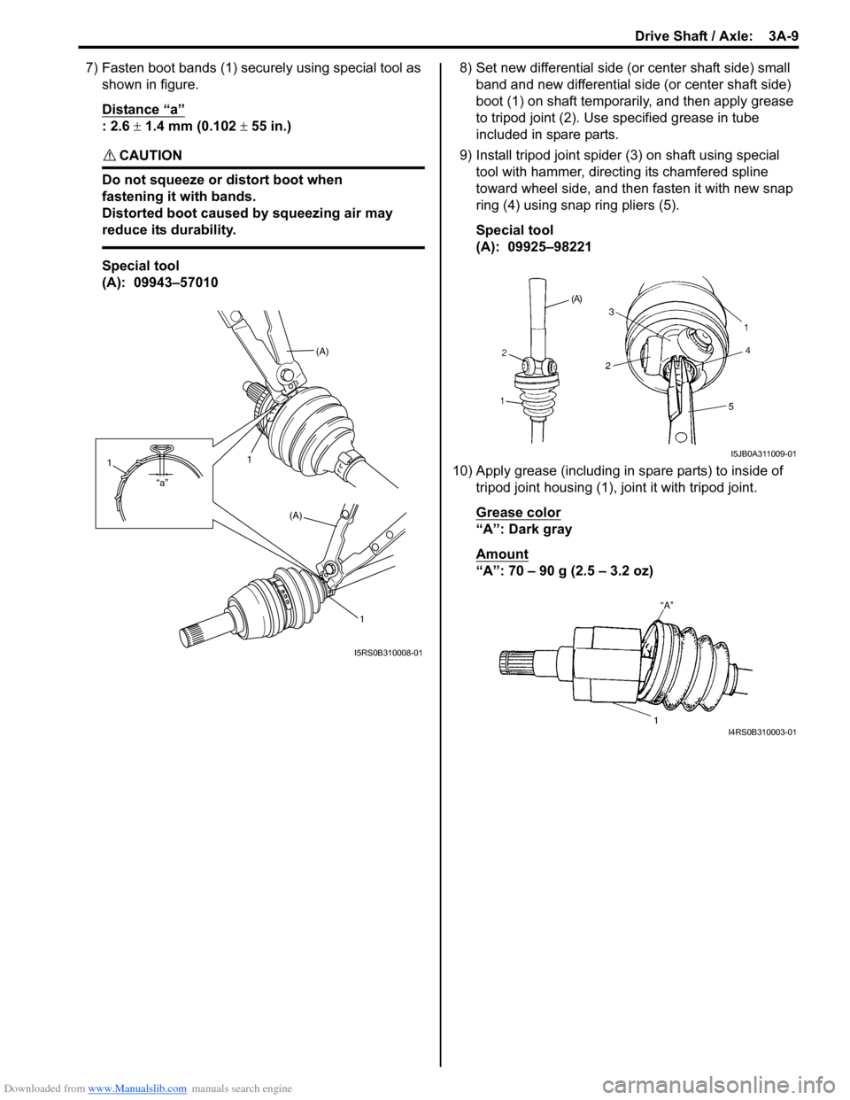
7) Fasten boot bands (1) securely using special tool as
shown in figure.
Distance “a”
: 2.6 ± 1.4 mm (0.102 ± 55 in.)
CAUTION!
Do not squeeze or distort boot when
fastening it with bands.
Distorted boot caused by squeezing air may
reduce its durability.
Special tool
(A): 09943–57010 8) Set new differential side (or center shaft side) small
band and new differential side (or center shaft side)
boot (1) on shaft temporarily, and then apply grease
to tripod joint (2). Use specified grease in tube
included in spare parts.
9) Install tripod joint spider (3) on shaft using special
tool with hammer, directing its chamfered spline
toward wheel side, and then fasten it with new snap
ring (4) using snap ring pliers (5).
Special tool
(A): 09925–98221
10) Apply grease (including in spare parts) to inside of tripod joint housing (1), jo int it with tripod joint.
Grease color
“A”: Dark gray
Amount
“A”: 70 – 90 g (2.5 – 3.2 oz)
(A)
1
(A)
1
“a”
1
I5RS0B310008-01
I5JB0A311009-01
I4RS0B310003-01
Page 488 of 1496
Downloaded from www.Manualslib.com manuals search engine 3A-10 Drive Shaft / Axle:
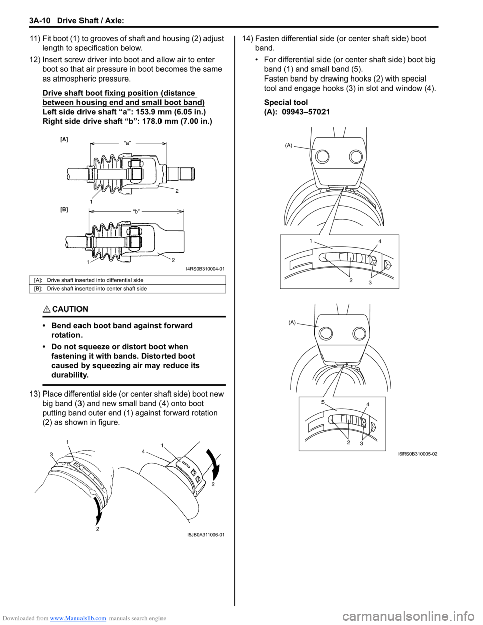
11) Fit boot (1) to grooves of shaft and housing (2) adjust
length to specification below.
12) Insert screw driver into boot and allow air to enter boot so that air pressure in boot becomes the same
as atmospheric pressure.
Drive shaft boot fixing position (distance
between housing end and small boot band)
Left side drive shaft “a”: 153.9 mm (6.05 in.)
Right side drive shaft “b”: 178.0 mm (7.00 in.)
CAUTION!
• Bend each boot band against forward rotation.
• Do not squeeze or distort boot when fastening it with bands. Distorted boot
caused by squeezing air may reduce its
durability.
13) Place differential side (or center shaft side) boot new big band (3) and new small band (4) onto boot
putting band outer end (1) against forward rotation
(2) as shown in figure. 14) Fasten differential side (or center shaft side) boot
band.
• For differential side (or center shaft side) boot big band (1) and small band (5).
Fasten band by drawing hooks (2) with special
tool and engage hooks (3) in slot and window (4).
Special tool
(A): 09943–57021
[A]: Drive shaft inserted into differential side
[B]: Drive shaft inserted into center shaft side
I4RS0B310004-01
I5JB0A311006-01
(A)
1 4
2 3
(A)
5 4
2 3
I6RS0B310005-02
Page 489 of 1496
Downloaded from www.Manualslib.com manuals search engine Drive Shaft / Axle: 3A-11
DOJ
Judging from abnormality noted before disassembly and
what is found through visual check of components parts
after disassembly, prepare replacing parts and proceed
to reassembly.
Make sure that wheel side joint assembly and DOJ
housing are washed thoroughly and air dried.
Replace boot(s) with new one(s).
CAUTION!
• Do not wash boots in degreaser such as gasoline or kerosene. etc. Washing in
degreaser causes deterioration of boot.
• To ensure full performance of joint as designed, be sure to distinguish between
two types of grease in repair set and apply
specified volume to respective joint
referring to the followings for identification
of the grease.
1) Wash disassembled parts (except boots). After washing, dry parts completely by blowing air.
2) Clean boots with cloth.
3) Apply grease to wheel side joint. Use specified
grease in tube in wheel side boot set as a spare
parts.
Grease color
: Black
Amount
: 55 – 75 g (1.9 – 2.6 oz)
4) Install wheel side boot on shaft.
5) Fill up boot inside wi th specified grease.
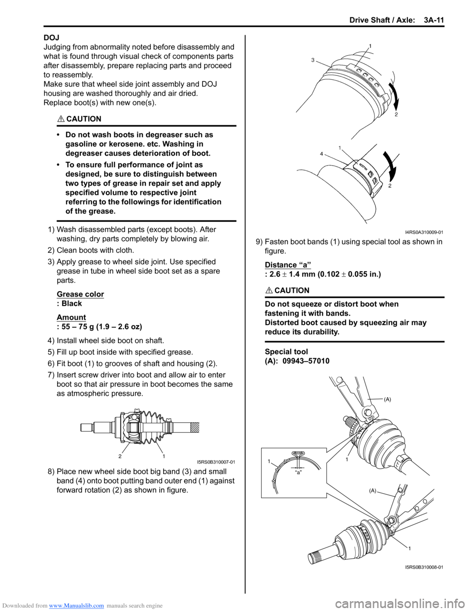
6) Fit boot (1) to grooves of shaft and housing (2).
7) Insert screw driver into boot and allow air to enter boot so that air pressure in boot becomes the same
as atmospheric pressure.
8) Place new wheel side boot big band (3) and small band (4) onto boot putting band outer end (1) against
forward rotation (2) as shown in figure. 9) Fasten boot bands (1) using special tool as shown in
figure.
Distance “a”
: 2.6 ± 1.4 mm (0.102 ± 0.055 in.)
CAUTION!
Do not squeeze or distort boot when
fastening it with bands.
Distorted boot caused by squeezing air may
reduce its durability.
Special tool
(A): 09943–57010
21I5RS0B310007-01
I4RS0A310009-01
(A)
1
(A)
1
“a”
1
I5RS0B310008-01
Page 490 of 1496
Downloaded from www.Manualslib.com manuals search engine 3A-12 Drive Shaft / Axle:
10) Set new differential side (or center shaft side) small band and new differential side (or center shaft side)
boot on shaft temporarily.
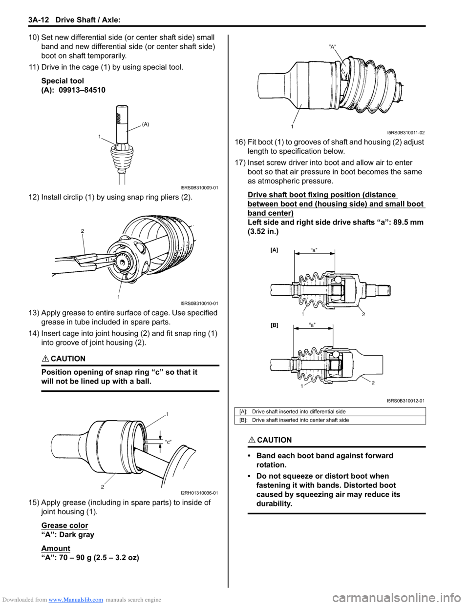
11) Drive in the cage (1) by using special tool.
Special tool
(A): 09913–84510
12) Install circlip (1) by using snap ring pliers (2).
13) Apply grease to entire su rface of cage. Use specified
grease in tube included in spare parts.
14) Insert cage into joint housing (2) and fit snap ring (1) into groove of joint housing (2).
CAUTION!
Position opening of snap ring “c” so that it
will not be lined up with a ball.
15) Apply grease (including in spare parts) to inside of joint housing (1).
Grease color
“A”: Dark gray
Amount
“A”: 70 – 90 g (2.5 – 3.2 oz) 16) Fit boot (1) to grooves of shaft and housing (2) adjust
length to specification below.
17) Inset screw driver into boot and allow air to enter boot so that air pressure in boot becomes the same
as atmospheric pressure.
Drive shaft boot fixing position (distance
between boot end (housing side) and small boot
band center)
Left side and right side drive shafts “a”: 89.5 mm
(3.52 in.)
CAUTION!
• Band each boot band against forward rotation.
• Do not squeeze or distort boot when fastening it with bands. Distorted boot
caused by squeezing air may reduce its
durability.
(A)
1
I5RS0B310009-01
I5RS0B310010-01
I2RH01310036-01
[A]: Drive shaft inserted into differential side
[B]: Drive shaft inserted into center shaft side
I5RS0B310011-02
I5RS0B310012-01
Page 492 of 1496
Downloaded from www.Manualslib.com manuals search engine 3A-14 Drive Shaft / Axle:
Center Shaft and Center Bearing Support
Disassembly and Reassembly
S7RS0B3106005
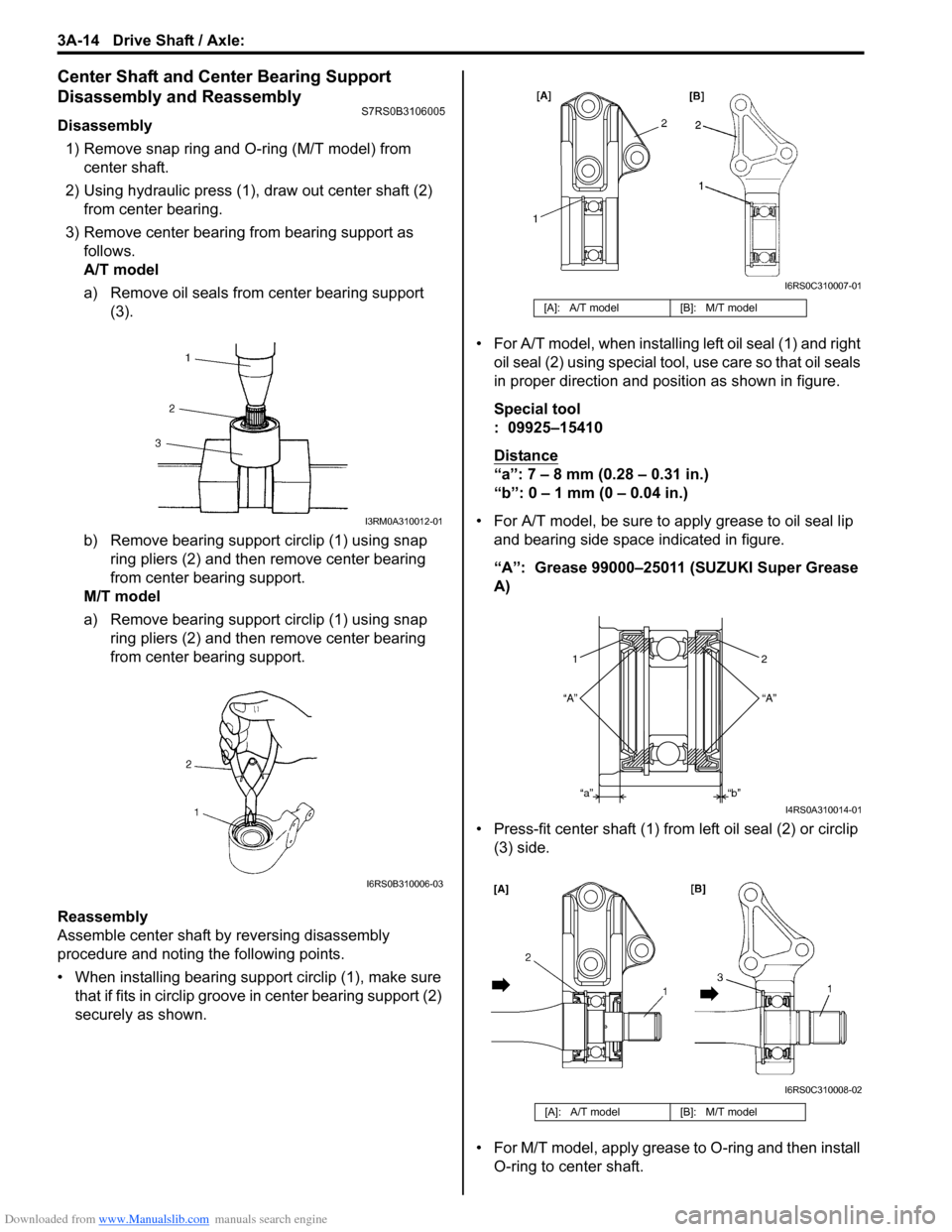
Disassembly1) Remove snap ring and O-ring (M/T model) from center shaft.
2) Using hydraulic press (1), draw out center shaft (2) from center bearing.
3) Remove center bearing from bearing support as follows.
A/T model
a) Remove oil seals from center bearing support (3).
b) Remove bearing support circlip (1) using snap ring pliers (2) and then remove center bearing
from center bearing support.
M/T model
a) Remove bearing support circlip (1) using snap ring pliers (2) and then remove center bearing
from center bearing support.
Reassembly
Assemble center shaft by reversing disassembly
procedure and noting the following points.
• When installing bearing support circlip (1), make sure
that if fits in circlip groove in center bearing support (2)
securely as shown. • For A/T model, when installing
left oil seal (1) and right
oil seal (2) using special tool, use care so that oil seals
in proper direction and position as shown in figure.
Special tool
: 09925–15410
Distance
“a”: 7 – 8 mm (0.28 – 0.31 in.)
“b”: 0 – 1 mm (0 – 0.04 in.)
• For A/T model, be sure to apply grease to oil seal lip and bearing side space indicated in figure.
“A”: Grease 99000–25011 (SUZUKI Super Grease
A)
• Press-fit center shaft (1) from left oil seal (2) or circlip
(3) side.
• For M/T model, apply grease to O-ring and then install O-ring to center shaft.
I3RM0A310012-01
I6RS0B310006-03
[A]: A/T model [B]: M/T model
[A]: A/T model [B]: M/T model
I6RS0C310007-01
12
“A” “A”
“a” “b”
I4RS0A310014-01
I6RS0C310008-02
Page 499 of 1496
Downloaded from www.Manualslib.com manuals search engine Brake Control System and Diagnosis: 4A-1
Brakes
Brake Control System and Diagnosis
Precautions
Precautions on BrakeS7RS0B4100001
Air Bag Warning
Refer to “Air Bag System Service Warning in Section 00”.
Brakes Diagnosis Note
Refer to “Brakes Diagnosis Note”.
General Description
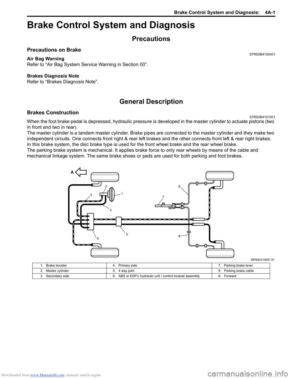
Brakes ConstructionS7RS0B4101001
When the foot brake pedal is depressed, hydraulic pressure is developed in the master cylinder to actuate pistons (two
in front and two in rear).
The master cylinder is a tandem master cylinder. Brake pipes are connected to the master cylinder and they make two
independent circuits. One connects front right & rear left brakes and the other connects front left & rear right brakes.
In this brake system, the disc brake type is used for the front wheel brake and the rear wheel brake.
The parking brake system is mechanical. It applies brake force to only rear wheels by means of the cable and
mechanical linkage system. The same brake shoes or pads are used for both parking and foot brakes.
A
5
3
2
1
4
8
8
6
7
I6RS0C410001-01
1. Brake booster 4. Primary side 7. Parking brake lever
2. Master cylinder 5. 4 way joint 8. Parking brake cable
3. Secondary side 6. ABS or ESP® hydraulic unit / control module assembly A: Forward
Page 500 of 1496
Downloaded from www.Manualslib.com manuals search engine 4A-2 Brake Control System and Diagnosis:
Brake Pedal Foot Protection System ConstructionS7RS0B4101004
Should a front crash occur and the engine push the dash panel toward the interior side, the brake pedal bracket is also
pushed toward the interior side. In this case, the brake pedal lever comes off from the brake pedal, thereby preventing
the brake pedal from moving rearward.
CAUTION!
Never disassemble brake pedal assembly. Disassemble will spoil its original function. If faulty
condition is found, replace it with new one.
[A]: Before crash2. Brake booster5. Brake pedal bracket
[B]: After crash 3. Brake pedal lever
1. Brake pedal 4. Booster push clevis rod
I6RW0C410001-02
Page 501 of 1496
Downloaded from www.Manualslib.com manuals search engine Brake Control System and Diagnosis: 4A-3
Front Brake Hose / Pipe ConstructionS7RS0B4101002
I7RS0B410003-01