2005 SUZUKI SWIFT throttle pedal
[x] Cancel search: throttle pedalPage 275 of 1496
Downloaded from www.Manualslib.com manuals search engine Engine Electrical Devices: 1C-3
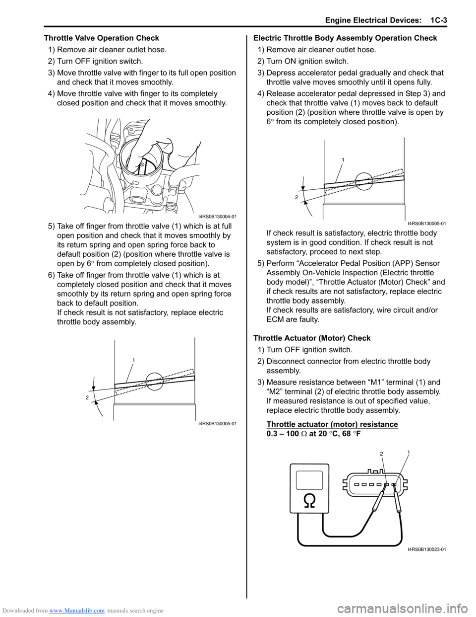
Throttle Valve Operation Check1) Remove air cleaner outlet hose.
2) Turn OFF ignition switch.
3) Move throttle valve with finger to its full open position and check that it moves smoothly.
4) Move throttle valve with fi nger to its completely
closed position and check that it moves smoothly.
5) Take off finger from throttle valve (1) which is at full open position and check that it moves smoothly by
its return spring and open spring force back to
default position (2) (positio n where throttle valve is
open by 6 ° from completely closed position).
6) Take off finger from throttle valve (1) which is at completely closed position and check that it moves
smoothly by its return spring and open spring force
back to default position.
If check result is not satisfactory, replace electric
throttle body assembly. Electric Throttle Body
Assembly Operation Check
1) Remove air cleaner outlet hose.
2) Turn ON ignition switch.
3) Depress accelerator pedal gradually and check that throttle valve moves smoo thly until it opens fully.
4) Release accelerator pedal depressed in Step 3) and check that throttle valve (1) moves back to default
position (2) (position where throttle valve is open by
6° from its completely closed position).
If check result is satisfactory, electric throttle body
system is in good condition. If check result is not
satisfactory, proceed to next step.
5) Perform “Accelerator Pe dal Position (APP) Sensor
Assembly On-Vehicle Inspection (Electric throttle
body model)”, “Throttle Actuator (Motor) Check” and
if check results are not satisfactory, replace electric
throttle body assembly.
If check results are satisfactory, wire circuit and/or
ECM are faulty.
Throttle Actuator (Motor) Check 1) Turn OFF ignition switch.
2) Disconnect connector from electric throttle body assembly.
3) Measure resistance between “M1” terminal (1) and “M2” terminal (2) of electric throttle body assembly.
If measured resistance is out of specified value,
replace electric throttle body assembly.
Throttle actuator (motor) resistance
0.3 – 100 Ω at 20 °C, 68 °F
I4RS0B130004-01
1
2
I4RS0B130005-01
1
2
I4RS0B130005-01
2 1
I4RS0B130023-01
Page 276 of 1496
Downloaded from www.Manualslib.com manuals search engine 1C-4 Engine Electrical Devices:
TP Sensor Performance Check1) Remove air cleaner outlet hose.
2) Turn OFF ignition switch.
3) Disconnect connector from electric throttle body assembly.
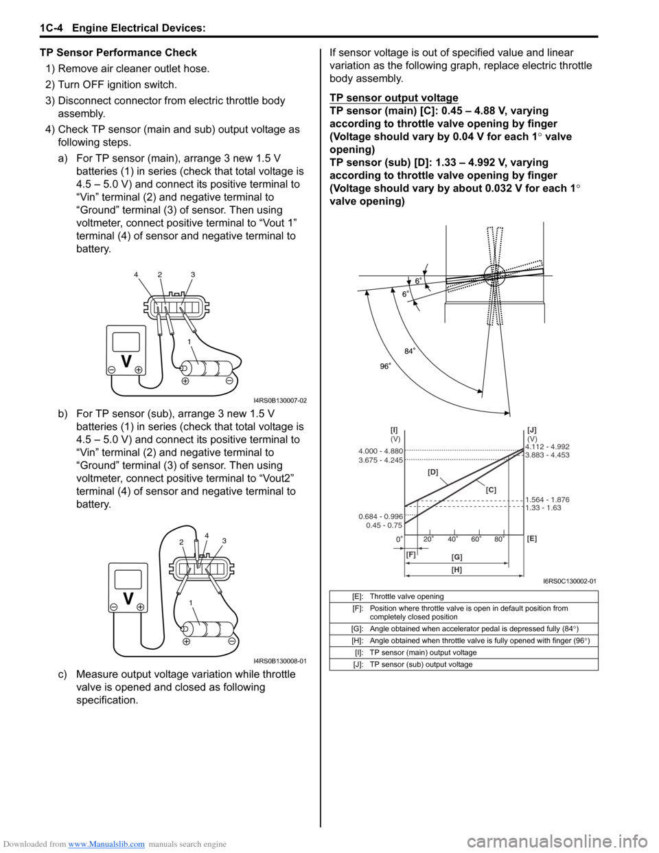
4) Check TP sensor (main and sub) output voltage as following steps.
a) For TP sensor (main), arrange 3 new 1.5 V batteries (1) in series (c heck that total voltage is
4.5 – 5.0 V) and connect its positive terminal to
“Vin” terminal (2) and negative terminal to
“Ground” terminal (3) of sensor. Then using
voltmeter, connect positive terminal to “Vout 1”
terminal (4) of sensor and negative terminal to
battery.
b) For TP sensor (sub), arrange 3 new 1.5 V batteries (1) in series (c heck that total voltage is
4.5 – 5.0 V) and connect its positive terminal to
“Vin” terminal (2) and negative terminal to
“Ground” terminal (3) of sensor. Then using
voltmeter, connect positive terminal to “Vout2”
terminal (4) of sensor and negative terminal to
battery.
c) Measure output voltage variation while throttle valve is opened and closed as following
specification. If sensor voltage is out of specified value and linear
variation as the following gra
ph, replace electric throttle
body assembly.
TP sensor output voltage
TP sensor (main) [C]: 0.45 – 4.88 V, varying
according to throttle valve opening by finger
(Voltage should vary by 0.04 V for each 1° valve
opening)
TP sensor (sub) [D]: 1.33 – 4.992 V, varying
according to throttle valve opening by finger
(Voltage should vary by about 0.032 V for each 1 °
valve opening)
1
42 3
I4RS0B130007-02
1
3
2 4
I4RS0B130008-01
[E]: Throttle valve opening
[F]: Position where throttle valve is open in default position from completely closed position
[G]: Angle obtained when accelerator pedal is depressed fully (84 °)
[H]: Angle obtained when throttle valve is fully opened with finger (96 °)
[I]: TP sensor (main) output voltage
[J]: TP sensor (sub) output voltage
[D]
[C][J]
(V)
[I]
(V)
[F] [G] [E]
0.45 - 0.75
0.684 - 0.996 3.675 - 4.245 4.000 - 4.880
1.33 - 1.63 1.564 - 1.876 3.883 - 4.453 4.112 - 4.992
[H]
I6RS0C130002-01
Page 277 of 1496
Downloaded from www.Manualslib.com manuals search engine Engine Electrical Devices: 1C-5
Electric Throttle Body System CalibrationS7RS0B1306004
NOTE
If working the service described under the
“Precautions of Electric Throttle Body
System Calibration in Section 1A” perform
following steps for electric throttle body
system calibration.
1) If electric throttle body assembly and/or APP sensor
assembly are replaced, perform following steps.
a) Disconnect negative cable at battery for 20 seconds or more for the purpose of clearing
calibration data of closed throttle position from
memory in ECM.
b) Connect negative cable to battery.
2) Keep ignition switch at ON position for 5 seconds or more without running engine.
APP Sensor Assembly On-Vehicle InspectionS7RS0B1306005
1) Check that APP sensor a ssembly has been mounted
to vehicle body properly (no pinched floor carpet,
etc.).
If mounting is not pro perly, reinstall APP sensor
assembly properly refe rring to “APP Sensor
Assembly Removal and Installation”.
2) Connect scan tool to DLC with ignition switch turned OFF.
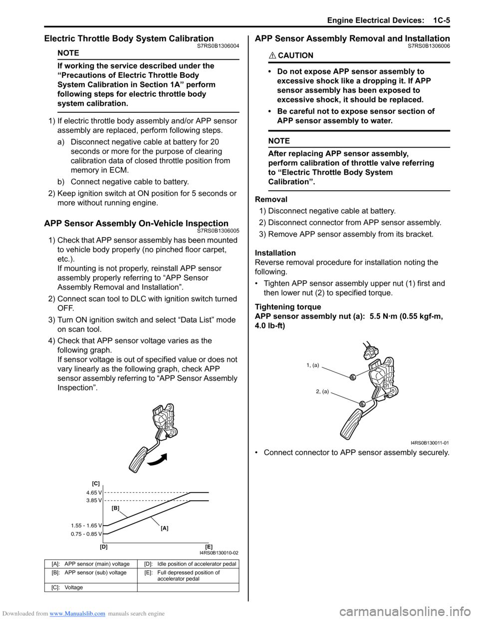
3) Turn ON ignition switch and select “Data List” mode on scan tool.
4) Check that APP sensor voltage varies as the following graph.
If sensor voltage is out of specified value or does not
vary linearly as the fo llowing graph, check APP
sensor assembly referring to “APP Sensor Assembly
Inspection”.
APP Sensor Assembly Removal and InstallationS7RS0B1306006
CAUTION!
• Do not expose APP sensor assembly to
excessive shock like a dropping it. If APP
sensor assembly has been exposed to
excessive shock, it should be replaced.
• Be careful not to expose sensor section of APP sensor assembly to water.
NOTE
After replacing APP sensor assembly,
perform calibration of th rottle valve referring
to “Electric Throttle Body System
Calibration”.
Removal
1) Disconnect negative cable at battery.
2) Disconnect connector from APP sensor assembly.
3) Remove APP sensor asse mbly from its bracket.
Installation
Reverse removal procedure for installation noting the
following.
• Tighten APP sensor assembly upper nut (1) first and then lower nut (2) to specified torque.
Tightening torque
APP sensor assembly nut (a): 5.5 N·m (0.55 kgf-m,
4.0 lb-ft)
• Connect connector to APP sensor assembly securely.
[A]: APP sensor (main) voltage [D]: Idle position of accelerator pedal
[B]: APP sensor (sub) voltage [E]: Full depressed position of
accelerator pedal
[C]: Voltage
[C]
[B]
[D] [E] [A]
4.65 V
3.85 V
1.55 - 1.65 V
0.75 - 0.85 V
I4RS0B130010-02
1, (a)
2, (a)
I4RS0B130011-01
Page 290 of 1496

Downloaded from www.Manualslib.com manuals search engine 1D-5 Engine Mechanical:
11) Connect negative cable at battery.
12) Install special tools (Compression gauge) into spark plug hole.
Special tool
(A): 09915–64512
(B): 09915–64530
(C): 09915–67010
13) Disengage clutch (1) (to lighten starting load on engine) for M/T vehicle, and depress accelerator
pedal (2) all the way to make throttle fully open.
14) Crank engine with fully charged battery, and read the highest pressure on compression gauge.
NOTE
• For measuring compression pressure, crank engine at least 250 r/min. by using
fully charged battery.
• If measured compression pressure is lower than limit value, check installation
condition of special tool. If it is properly
installed, possibility is compression
pressure leakage from where piston ring
and valve contact.
Compression pressure
Standard: 1400 kPa (14.0 kg/cm2, 199.0 psi)
Limit: 1100 kPa (11.0 kg/cm2, 156.0 psi)
Max. difference between any two cylinders: 100
kPa (1.0 kg/cm
2, 14.2 psi) 15) Carry out Steps 12) through 14) on each cylinder to
obtain 4 readings.
16) Disconnect negative cable at battery.
17) After checking, install spark plugs and ignition coil assemblies (2) with high-tension cord (3).
18) Connect ignition coil couplers (1).
19) Connect fuel injector wires (4) at the coupler.
20) Install cylinder head upper cover.
21) Install air cleaner assembly and air suction hose referring to “Air Cleaner Components”.
22) Install engine cover.
23) Connect negative cable at battery.
Engine Vacuum CheckS7RS0B1404002
The engine vacuum that develops in the intake line is a
good indicator of the condition of the engine. The
vacuum checking procedure is as follows:
1) Warm up engine to normal operating temperature.
NOTE
After warming up engine, be sure to place
transaxle gear shift lever in “Neutral”, and set
parking brake and block drive wheels.
2) Stop engine and turn off the all electric switches.
3) Remove engine cover.
4) Remove air cleaner assembly and air suction hose referring to “Air Cleaner Components”.
5) Remove PCV hose (1) from PCV valve (2).
(A)
(C)
(B)
I3RH0B140009-01
I2RH0B140005-01
I2RH0B140003-01
2
1
I6RS0B141001-01
Page 653 of 1496
Downloaded from www.Manualslib.com manuals search engine Automatic Transmission/Transaxle: 5A-9
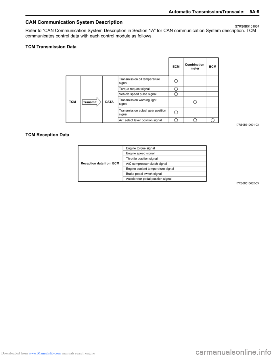
CAN Communication System DescriptionS7RS0B5101007
Refer to “CAN Communication System Description in Section 1A” for CAN communication System description. TCM
communicates control data with each control module as follows.
TCM Transmission Data
TCM Reception Data
DATA
TCM
Transmit
Transmission oil temperarure
signal
Torque request signal
Vehicle speed pulse signal
Transmission warning light
signal
Transmission actual gear position
signal
A/T select lever position signal
ECMCombination
meterBCM
I7RS0B510001-03
Engine torque signal
Engine speed signal
Throttle position signal
A/C compressor clutch signal
Engine coolant temperature signal
Brake pedal switch signal
Reception data from ECM
Accelerator pedal position signalI7RS0B510002-03
Page 658 of 1496
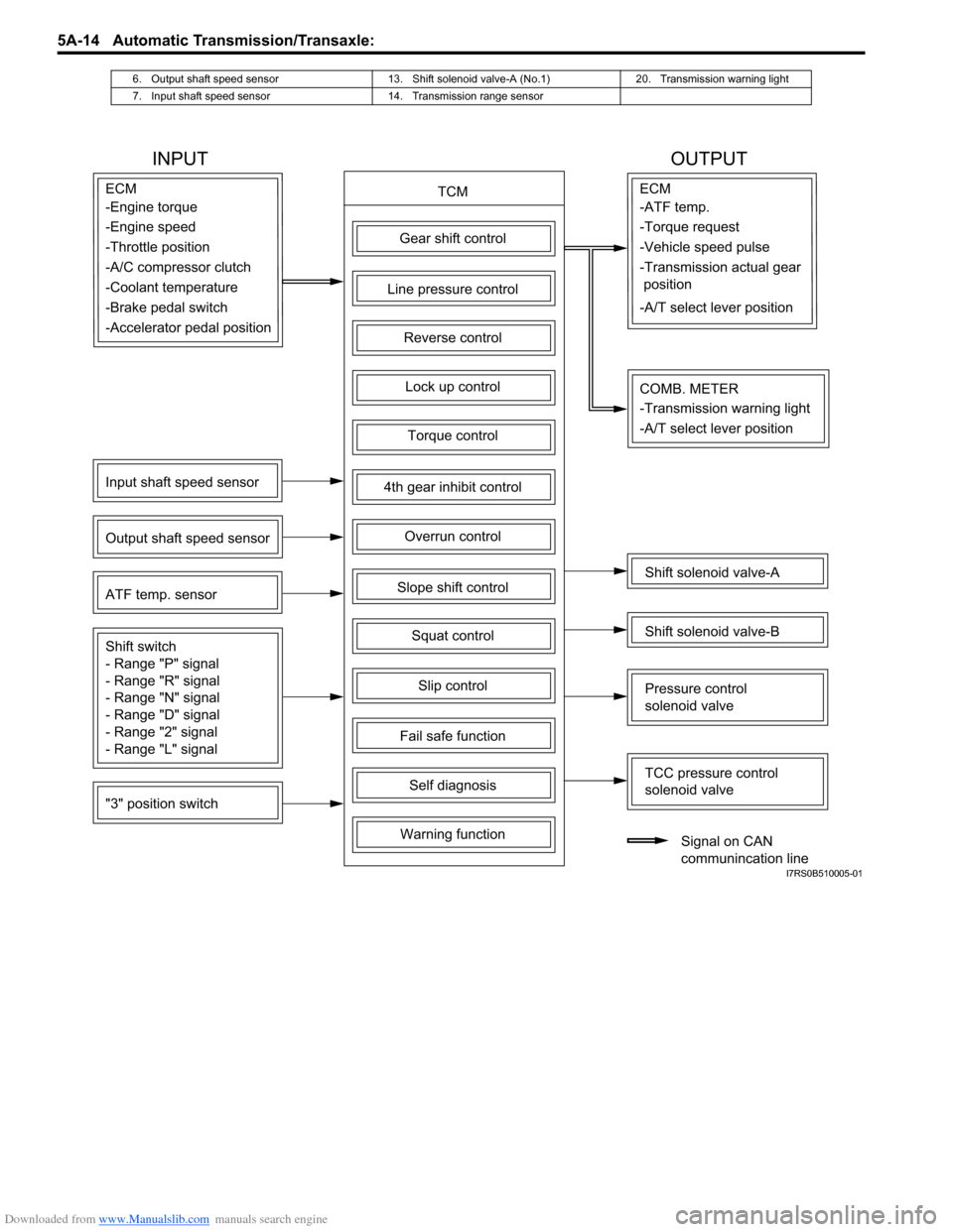
Downloaded from www.Manualslib.com manuals search engine 5A-14 Automatic Transmission/Transaxle:
6. Output shaft speed sensor 13. Shift solenoid valve-A (No.1) 20. Transmission warning light
7. Input shaft speed sensor 14. Transmission range sensor
INPUT OUTPUT
TCMECM
Gear shift control
4th gear inhibit control
Slope shift control
Slip control
Lock up control
Torque control
Line pressure control
Overrun control
Reverse control
Squat control
Input shaft speed sensor
Output shaft speed sensor
"3" position switch ATF temp. sensor
Shift switch
- Range "P" signal
- Range "R" signal
- Range "N" signal
- Range "D" signal
- Range "2" signal
- Range "L" signal
Fail safe function
Self diagnosis
Warning function
ECM
Shift solenoid valve-A
Shift solenoid valve-B
TCC pressure control
solenoid valve
Pressure control
solenoid valve
Signal on CAN
communincation line
COMB. METER
-Engine torque
-Engine speed
-Throttle position
-A/C compressor clutch
-Coolant temperature
-Brake pedal switch -ATF temp.
-Torque request
-Vehicle speed pulse
-Transmission actual gear
position
-A/T select lever position
-Accelerator pedal position
-Transmission warning light
-A/T select lever position
I7RS0B510005-01
Page 668 of 1496
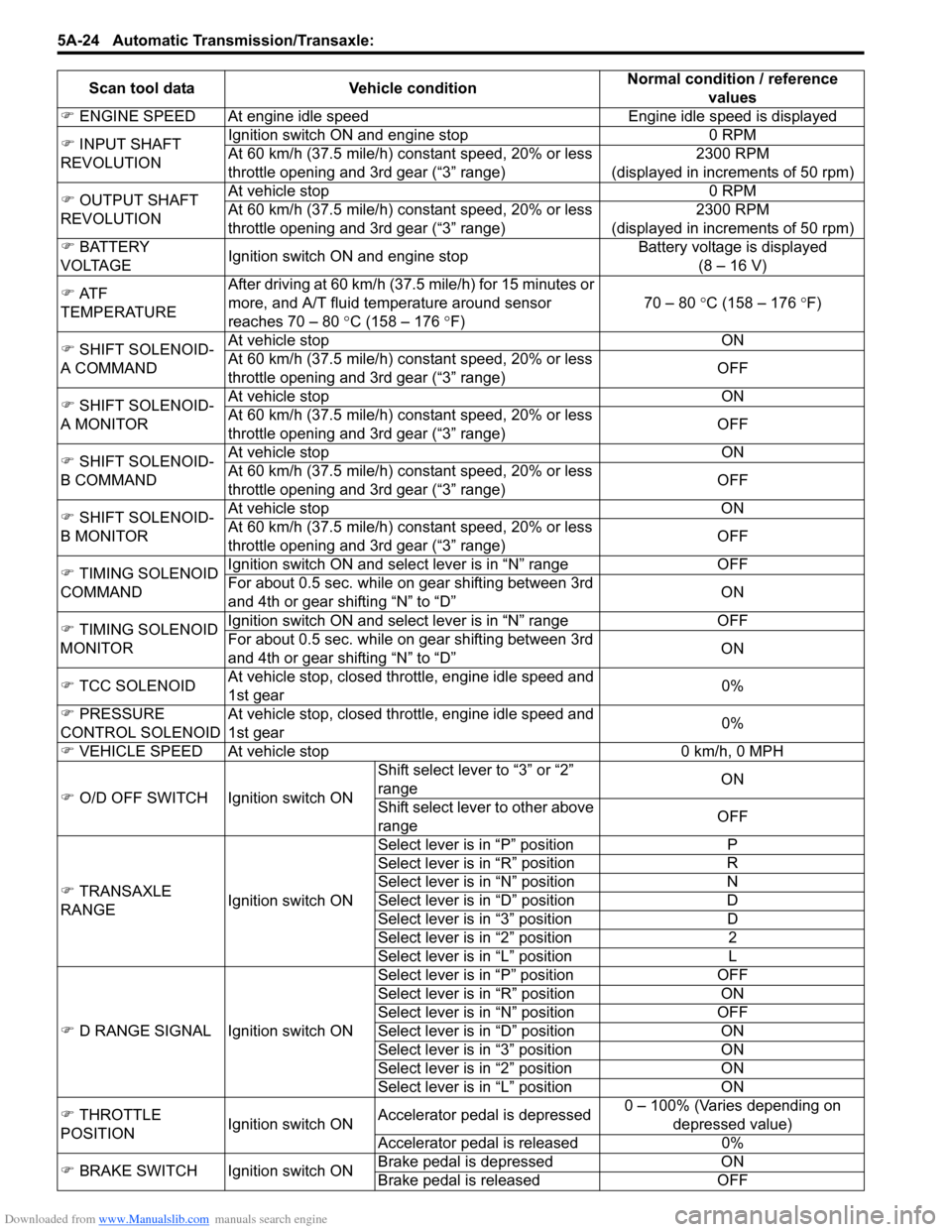
Downloaded from www.Manualslib.com manuals search engine 5A-24 Automatic Transmission/Transaxle:
�) ENGINE SPEED At engine idle spee d Engine idle speed is displayed
�) INPUT SHAFT
REVOLUTION Ignition switch ON and engine stop 0 RPM
At 60 km/h (37.5 mile/h) constant speed, 20% or less
throttle opening and 3rd gear (“3” range)
2300 RPM
(displayed in increments of 50 rpm)
�) OUTPUT SHAFT
REVOLUTION At vehicle stop 0 RPM
At 60 km/h (37.5 mile/h) constant speed, 20% or less
throttle opening and 3rd gear (“3” range)
2300 RPM
(displayed in increments of 50 rpm)
�) BATTERY
VOLTAGE Ignition switch ON and engine stop Battery voltage is displayed
(8 – 16 V)
�) AT F
TEMPERATURE After driving at 60 km/h (37.5 mile/h) for 15 minutes or
more, and A/T fluid temperature around sensor
reaches 70 – 80
°C (158 – 176 °F) 70 – 80
°C (158 – 176 °F)
�) SHIFT SOLENOID-
A COMMAND At vehicle stop ON
At 60 km/h (37.5 mile/h) constant speed, 20% or less
throttle opening and 3rd gear (“3” range)
OFF
�) SHIFT SOLENOID-
A MONITOR At vehicle stop ON
At 60 km/h (37.5 mile/h) constant speed, 20% or less
throttle opening and 3rd gear (“3” range)
OFF
�) SHIFT SOLENOID-
B COMMAND At vehicle stop ON
At 60 km/h (37.5 mile/h) constant speed, 20% or less
throttle opening and 3rd gear (“3” range)
OFF
�) SHIFT SOLENOID-
B MONITOR At vehicle stop ON
At 60 km/h (37.5 mile/h) constant speed, 20% or less
throttle opening and 3rd gear (“3” range)
OFF
�) TIMING SOLENOID
COMMAND Ignition switch ON and sele
ct lever is in “N” range OFF
For about 0.5 sec. while on gear shifting between 3rd
and 4th or gear shifting “N” to “D” ON
�) TIMING SOLENOID
MONITOR Ignition switch ON and sele
ct lever is in “N” range OFF
For about 0.5 sec. while on gear shifting between 3rd
and 4th or gear shifting “N” to “D” ON
�) TCC SOLENOID At vehicle stop, closed throttle, engine idle speed and
1st gear 0%
�) PRESSURE
CONTROL SOLENOID At vehicle stop, closed throttle, engine idle speed and
1st gear
0%
�) VEHICLE SPEED At vehicle stop 0 km/h, 0 MPH
�) O/D OFF SWITCH Ignition switch ON Shift select lever to “3” or “2”
range
ON
Shift select lever to other above
range OFF
�) TRANSAXLE
RANGE Ignition switch ONSelect lever is in “P” position P
Select lever is in “R
” position R
Select lever is in “N” position N
Select lever is in “D” position D
Select lever is in “3” position D
Select lever is in “2” position 2
Select lever is in “L” position L
�) D RANGE SIGNAL Ignition switch ON Select lever is in “P” position
OFF
Select lever is in “R” position ON
Select lever is in “N” position OFF
Select lever is in “D” position ON
Select lever is in “3” position ON
Select lever is in “2” position ON
Select lever is in “L” position ON
�) THROTTLE
POSITION Ignition switch ONAccelerator peda
l is depressed 0 – 100% (Varies depending on
depressed value)
Accelerator peda l is released 0%
�) BRAKE SWITCH Ignition switch ON Brake pedal is depressed
ON
Brake pedal is released OFF
Scan tool data
Vehicle condition Normal condition / reference
values
Page 670 of 1496
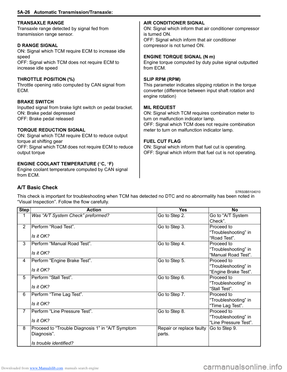
Downloaded from www.Manualslib.com manuals search engine 5A-26 Automatic Transmission/Transaxle:
TRANSAXLE RANGE
Transaxle range detected by signal fed from
transmission range sensor.
D RANGE SIGNAL
ON: Signal which TCM require ECM to increase idle
speed
OFF: Signal which TCM does not require ECM to
increase idle speed
THROTTLE POSITION (%)
Throttle opening ratio computed by CAN signal from
ECM.
BRAKE SWITCH
Inputted signal from brake light switch on pedal bracket.
ON: Brake pedal depressed
OFF: Brake pedal released
TORQUE REDUCTION SIGNAL
ON: Signal which TCM require ECM to reduce output
torque at shifting gear
OFF: Signal which TCM does not require ECM to reduce
output torque
ENGINE COOLANT TEMPERATURE ( °C, °F)
Engine coolant temperature computed by CAN signal
from ECM. AIR CONDITIONER SIGNAL
ON: Signal which inform that air conditioner compressor
is turned ON.
OFF: Signal which inform that air conditioner
compressor is not turned ON.
ENGINE TORQUE SIGNAL (N
⋅m)
Engine torque computed by duty pulse signal outputted
from ECM.
SLIP RPM (RPM)
This parameter indicates slip ping rotation in the torque
converter (difference between input shaft rotation and
engine rotation)
MIL REQUEST
ON: Signal which TCM requires combination meter to
turn on malfunction indicator lamp.
OFF: Signal which TCM does not require combination
meter to turn on malf unction indicator lamp.
FUEL CUT FLAG
ON: Signal which inform that fuel cut is operating.
OFF: Signal which inform that fuel cut is not operating.
A/T Basic CheckS7RS0B5104010
This check is important for troubleshooting when TCM has detected no DTC and no abnormality has been noted in
“Visual Inspection”. Fo llow the flow carefully.
Step Action YesNo
1 Was “A/T System Check” preformed? Go to Step 2.Go to “A/T System
Check”.
2 Perform “Road Test”.
Is it OK? Go to Step 3.
Proceed to
“Troubleshooting” in
“Road Test”.
3 Perform “Manual Road Test”.
Is it OK? Go to Step 4.
Proceed to
“Troubleshooting” in
“Manual Road Test”.
4 Perform “Engine Brake Test”.
Is it OK? Go to Step 5.
Proceed to
“Troubleshooting” in
“Engine Brake Test”.
5 Perform “Stall Test”.
Is it OK? Go to Step 6.
Proceed to
“Troubleshooting” in
“Stall Test”.
6 Perform “Time Lag Test”.
Is it OK? Go to Step 7.
Proceed to
“Troubleshooting” in
“Time Lag Test”.
7 Perform “Line Pressure Test”.
Is it OK? Go to Step 8.
Proceed to
“Troubleshooting” in
“Line Pressure Test”.
8 Proceed to “Trouble Diag nosis 1” in “A/T Symptom
Diagnosis”.
Is trouble identified? Repair or replace faulty
parts.
Go to Step 9.