2005 SUZUKI SWIFT oil temperature
[x] Cancel search: oil temperaturePage 956 of 1496
Downloaded from www.Manualslib.com manuals search engine 7B-8 Air Conditioning System: Manual Type
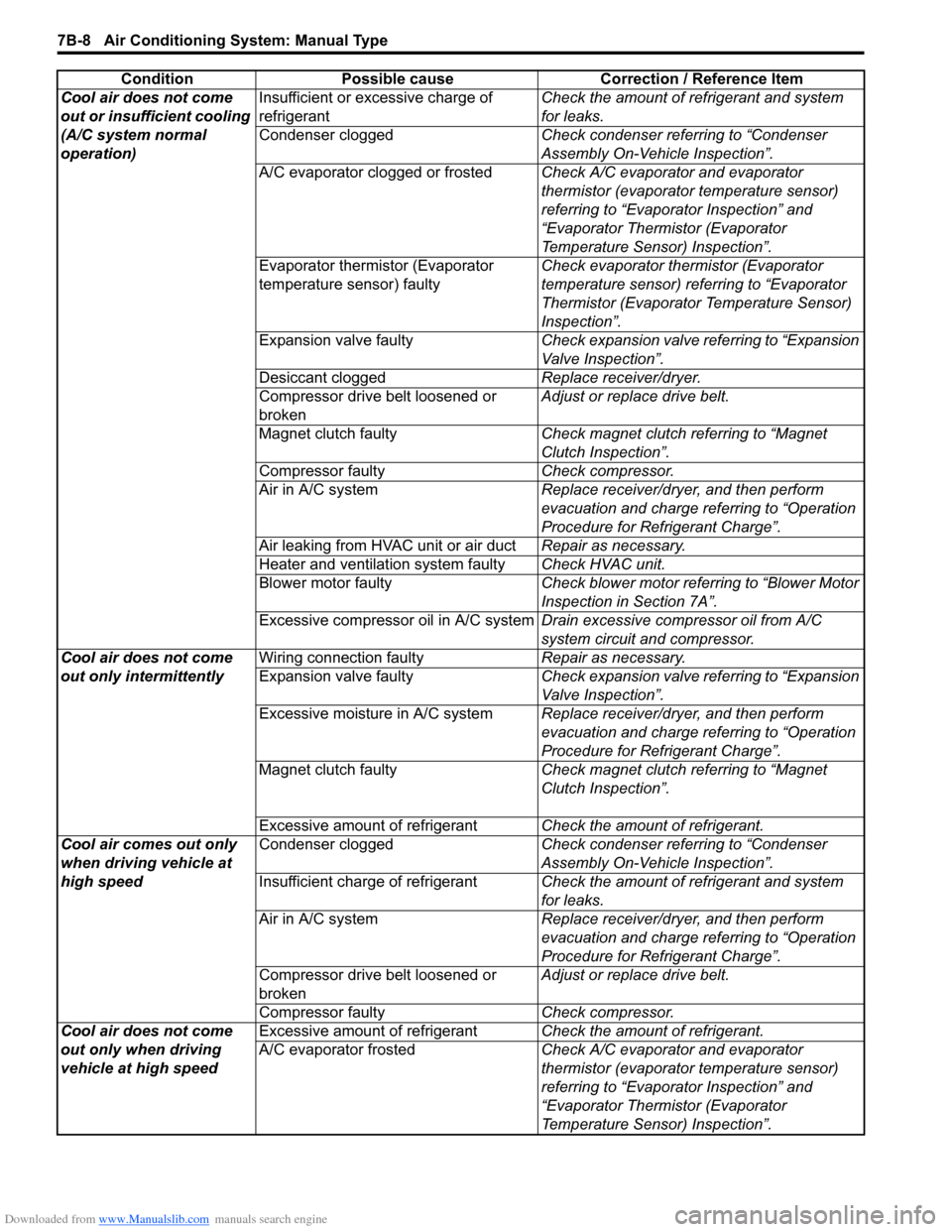
Cool air does not come
out or insufficient cooling
(A/C system normal
operation)Insufficient or excessive charge of
refrigerant
Check the amount of refrigerant and system
for leaks.
Condenser clogged Check condenser referring to “Condenser
Assembly On-Vehicle Inspection”.
A/C evaporator clogged or frosted Check A/C evaporator and evaporator
thermistor (evaporator temperature sensor)
referring to “Evaporator Inspection” and
“Evaporator Thermistor (Evaporator
Temperature Sensor) Inspection”.
Evaporator thermistor (Evaporator
temperature sensor) faulty Check evaporator thermistor (Evaporator
temperature sensor) referring to “Evaporator
Thermistor (Evaporator Temperature Sensor)
Inspection”.
Expansion valve faulty Check expansion valve referring to “Expansion
Valve Inspection”.
Desiccant clogged Replace receiver/dryer.
Compressor drive belt loosened or
broken Adjust or replace drive belt.
Magnet clutch faulty Check magnet clutch referring to “Magnet
Clutch Inspection”.
Compressor faulty Check compressor.
Air in A/C system Replace receiver/dryer, and then perform
evacuation and charge referring to “Operation
Procedure for Refrigerant Charge”.
Air leaking from HVAC unit or air duct Repair as necessary.
Heater and ventilation system faulty Check HVAC unit.
Blower motor faulty Check blower motor referring to “Blower Motor
Inspection in Section 7A”.
Excessive compressor oil in A/C system Drain excessive compressor oil from A/C
system circuit and compressor.
Cool air does not come
out only intermittently Wiring connection faulty
Repair as necessary.
Expansion valve faulty Check expansion valve referring to “Expansion
Valve Inspection”.
Excessive moisture in A/C system Replace receiver/dryer, and then perform
evacuation and charge referring to “Operation
Procedure for Refrigerant Charge”.
Magnet clutch faulty Check magnet clutch referring to “Magnet
Clutch Inspection”.
Excessive amount of refrigerant Check the amount of refrigerant.
Cool air comes out only
when driving vehicle at
high speed Condenser clogged
Check condenser referring to “Condenser
Assembly On-Vehicle Inspection”.
Insufficient charge of refrigerant Check the amount of refrigerant and system
for leaks.
Air in A/C system Replace receiver/dryer, and then perform
evacuation and charge referring to “Operation
Procedure for Refrigerant Charge”.
Compressor drive belt loosened or
broken Adjust or replace drive belt.
Compressor faulty Check compressor.
Cool air does not come
out only when driving
vehicle at high speed Excessive amount of refrigerant
Check the amount of refrigerant.
A/C evaporator frosted Check A/C evaporator and evaporator
thermistor (evaporator temperature sensor)
referring to “Evaporator Inspection” and
“Evaporator Thermistor (Evaporator
Temperature Sensor) Inspection”.
Condition Possible cause Correction / Reference Item
Page 957 of 1496
Downloaded from www.Manualslib.com manuals search engine Air Conditioning System: Manual Type 7B-9
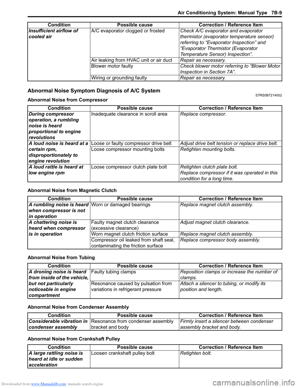
Abnormal Noise Symptom Diagnosis of A/C SystemS7RS0B7214002
Abnormal Noise from Compressor
Abnormal Noise from Magnetic Clutch
Abnormal Noise from Tubing
Abnormal Noise from Condenser Assembly
Abnormal Noise from Crankshaft PulleyInsufficient airflow of
cooled air
A/C evaporator clogged or frosted
Check A/C evaporator and evaporator
thermistor (evaporator temperature sensor)
referring to “Evaporator Inspection” and
“Evaporator Thermistor (Evaporator
Temperature Sensor) Inspection”.
Air leaking from HVAC unit or air duct Repair as necessary.
Blower motor faulty Check blower motor referring to “Blower Motor
Inspection in Section 7A”.
Wiring or grounding faulty Repair as necessary.
Condition Possible cause Correction / Reference Item
Condition
Possible cause Correction / Reference Item
During compressor
operation, a rumbling
noise is heard
proportional to engine
revolutions Inadequate clearance in scroll area
Replace compressor.
A loud noise is heard at a
certain rpm,
disproportionately to
engine revolution Loose or faulty compressor drive belt
Adjust drive belt tension or replace drive belt.
Loose compressor mounting bolts Retighten mounting bolts.
A loud rattle is heard at
low engine rpm Loose compressor clutch plate bolt
Retighten clutch plate bolt.
Replace compressor if it was operated in this
condition for a long time.
Condition Possible cause Correction / Reference Item
A rumbling noise is heard
when compressor is not
in operation Worn or damaged bearings
Replace magnet clutch assembly.
A chattering noise is
heard when compressor
is in operation Faulty magnet clutch clearance
(excessive clearance)
Adjust magnet clutch clearance.
Worn magnet clutch friction surface Replace magnet clutch assembly.
Compressor oil leaked from shaft seal,
contaminating the friction surface Replace compressor body assembly.
Condition
Possible cause Correction / Reference Item
A droning noise is heard
from inside of the vehicle,
but not particularly
noticeable in engine
compartment Faulty tubing clamps
Reposition clamps or increase the number of
clamps.
Resonance caused by pulsation from
variations in re frigerant pressure Attach a silencer to tubing, or modify its
position and length.
Condition
Possible cause Correction / Reference Item
Considerable vibration in
condenser assembly Resonance from condenser assembly
bracket and body Firmly insert a silenc
er between condenser
assembly bracket and body.
Condition Possible cause Correction / Reference Item
A large rattling noise is
heard at idle or sudden
acceleration Loosen crankshaft pulley bolt
Retighten bolt.
Page 972 of 1496

Downloaded from www.Manualslib.com manuals search engine 7B-24 Air Conditioning System: Manual Type
HVAC Unit Removal and InstallationS7RS0B7216006
Removal1) Disconnect negative (–) cable from battery.
2) Disable air bag system referring to “Disabling Air Bag System in Section 8B”.
3) Recover refrigerant from A/C system with recovery and recycling equipment referring to “Recovery” in
“Operation Procedure for Refrigerant Charge”.
4) Remove cowl top panel referring to “Cowl Top Components in Section 9K”.
5) Drain engine coolant, and then disconnect heater hoses (1) from HVAC unit (2).
6) Remove instrument panel from vehicle body referring to “Audio Unit Re moval and Installation in
Section 9C”.
7) Loosen suction hose and liquid pipe bolt (4).
8) Remove nuts (3).
9) Remove HVAC unit from vehicle body. Installation
Reverse removal procedure noting the following
instructions.
• Replenish specified amount of compressor oil to
compressor suction side referring to “Replenishing
Compressor Oil” in “Operation Procedure for
Refrigerant Charge”.
• Install the padding (1) to the installation hole uniformly.
• Evacuate and charge the A/C system referring to “Evacuation” and “Charge” in “Operation Procedure
for Refrigerant Charge”.
• Adjust control cables referr ing to “HVAC Control Unit
Removal and Installati on in Section 7A”.
• Enable air bag system referring to “Enabling Air Bag System in Section 8B”.
Evaporator InspectionS7RS0B7216007
Check the followings.
• Clog of A/C evaporator fins.If any clogs are found, A/C evaporator fins should be
washed with water, and then should be dried with
compressed air.
• A/C evaporator fins for leakage and breakage. If any defects are found, repair or replace A/C
evaporator.
• A/C evaporator fittings for leakage. If any defects are found, repair or replace A/C
evaporator.
2. Blower upper case 8. Temperature control door assembly 14. Temperature control lever 20. Packing
3. Air intake control actuator 9. Blower motor resistor 15. Airflow control lever21. Filter cover (if equipped)
4. HVAC Air filter (if equipped) 10. Blower lower case 16. Evaporator22. Drain hose
5. Heater unit upper case 11. Blower motor 17. O-ring23. Cable lock clamp
6. Foot duct 12. Heater unit lower case 18. Expansion valve: Do not reuse.
3
2
3
3
1
4
I4RS0B720009-01
1
I4RS0B720010-01
Page 989 of 1496
Downloaded from www.Manualslib.com manuals search engine Air Conditioning System: Automatic Type 7B-41
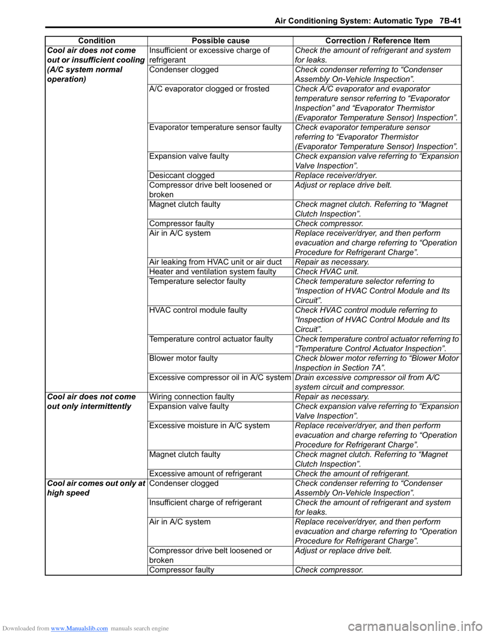
Cool air does not come
out or insufficient cooling
(A/C system normal
operation)Insufficient or excessive charge of
refrigerant
Check the amount of refrigerant and system
for leaks.
Condenser clogged Check condenser referring to “Condenser
Assembly On-Vehicle Inspection”.
A/C evaporator clogged or frosted Check A/C evaporator and evaporator
temperature sensor referring to “Evaporator
Inspection” and “Evaporator Thermistor
(Evaporator Temperature Sensor) Inspection”.
Evaporator temperature sensor faulty Check evaporator temperature sensor
referring to “Evaporator Thermistor
(Evaporator Temperature Sensor) Inspection”.
Expansion valve faulty Check expansion valve referring to “Expansion
Valve Inspection”.
Desiccant clogged Replace receiver/dryer.
Compressor drive belt loosened or
broken Adjust or replace drive belt.
Magnet clutch faulty Check magnet clutch. Referring to “Magnet
Clutch Inspection”.
Compressor faulty Check compressor.
Air in A/C system Replace receiver/dryer, and then perform
evacuation and charge referring to “Operation
Procedure for Refrigerant Charge”.
Air leaking from HVAC unit or air duct Repair as necessary.
Heater and ventilation system faulty Check HVAC unit.
Temperature selector faulty Check temperature selector referring to
“Inspection of HVAC Control Module and Its
Circuit”.
HVAC control module faulty Check HVAC control module referring to
“Inspection of HVAC Control Module and Its
Circuit”.
Temperature control actuator faulty Check temperature control actuator referring to
“Temperature Control Actuator Inspection”.
Blower motor faulty Check blower motor referring to “Blower Motor
Inspection in Section 7A”.
Excessive compressor oil in A/C system Drain excessive compressor oil from A/C
system circuit and compressor.
Cool air does not come
out only intermittently Wiring connection faulty
Repair as necessary.
Expansion valve faulty Check expansion valve referring to “Expansion
Valve Inspection”.
Excessive moisture in A/C system Replace receiver/dryer, and then perform
evacuation and charge referring to “Operation
Procedure for Refrigerant Charge”.
Magnet clutch faulty Check magnet clutch. Referring to “Magnet
Clutch Inspection”.
Excessive amount of refrigerant Check the amount of refrigerant.
Cool air comes out only at
high speed Condenser clogged
Check condenser referring to “Condenser
Assembly On-Vehicle Inspection”.
Insufficient charge of refrigerant Check the amount of refrigerant and system
for leaks.
Air in A/C system Replace receiver/dryer, and then perform
evacuation and charge referring to “Operation
Procedure for Refrigerant Charge”.
Compressor drive belt loosened or
broken Adjust or replace drive belt.
Compressor faulty Check compressor.
Condition Possible cause Correction / Reference Item
Page 1040 of 1496
Downloaded from www.Manualslib.com manuals search engine 8B-2 Air Bag System:
Precautions on Handling and Storage of Air Bag
System Components
S7RS0B8200002
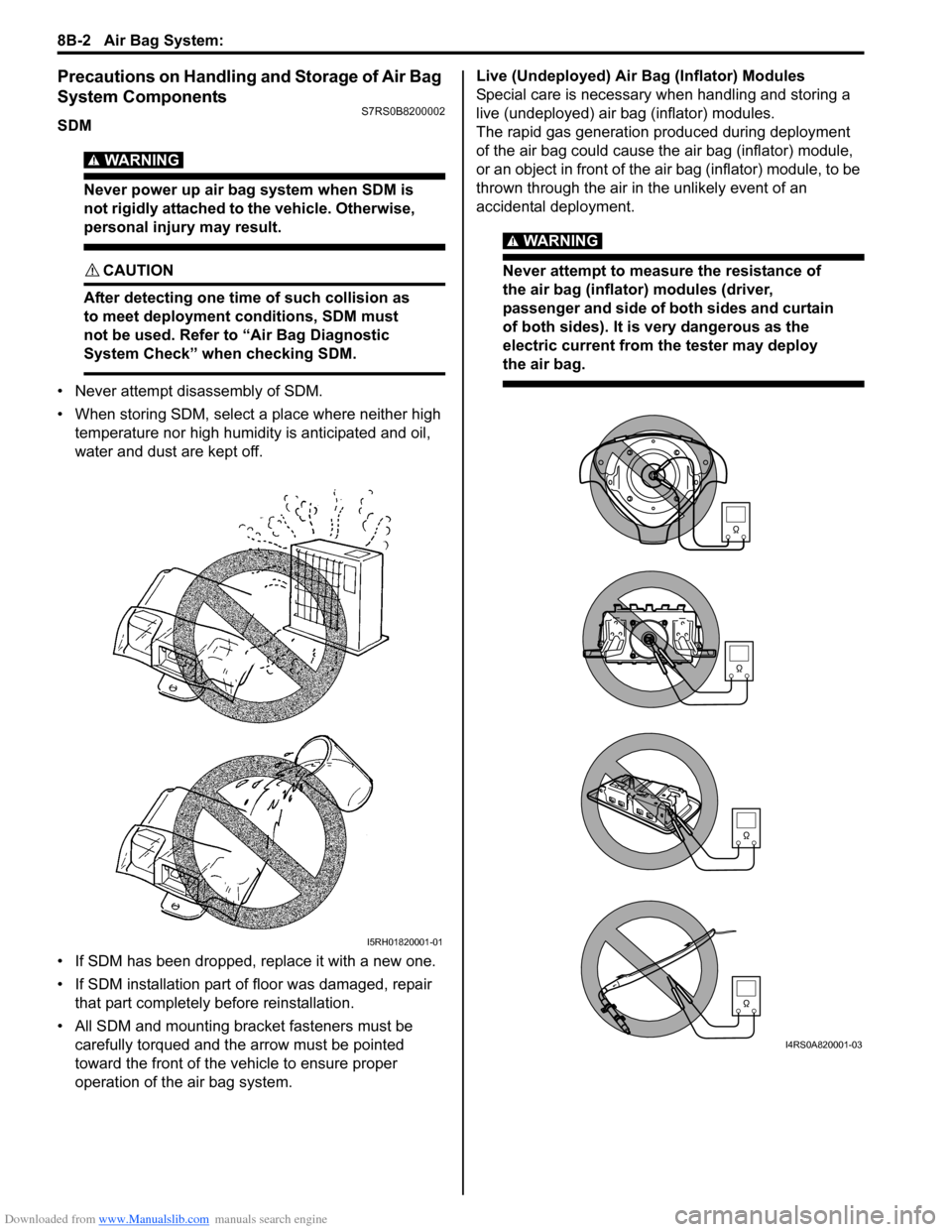
SDM
WARNING!
Never power up air bag system when SDM is
not rigidly attached to the vehicle. Otherwise,
personal injury may result.
CAUTION!
After detecting one time of such collision as
to meet deployment conditions, SDM must
not be used. Refer to “Air Bag Diagnostic
System Check” when checking SDM.
• Never attempt disassembly of SDM.
• When storing SDM, select a place where neither high temperature nor high humidity is anticipated and oil,
water and dust are kept off.
• If SDM has been dropped, replace it with a new one.
• If SDM installation part of floor was damaged, repair that part completely before reinstallation.
• All SDM and mounting bracket fasteners must be carefully torqued and the arrow must be pointed
toward the front of the vehicle to ensure proper
operation of the air bag system. Live (Undeployed) Air Bag (Inflator) Modules
Special care is necessary when handling and storing a
live (undeployed) air bag (inflator) modules.
The rapid gas generation produced during deployment
of the air bag could cause the air bag (inflator) module,
or an object in front of the air bag (inflator) module, to be
thrown through the air in the unlikely event of an
accidental deployment.
WARNING!
Never attempt to measure the resistance of
the air bag (inflator) modules (driver,
passenger and side of both sides and curtain
of both sides). It is
very dangerous as the
electric current from the tester may deploy
the air bag.
I5RH01820001-01
I4RS0A820001-03
Page 1041 of 1496
Downloaded from www.Manualslib.com manuals search engine Air Bag System: 8B-3
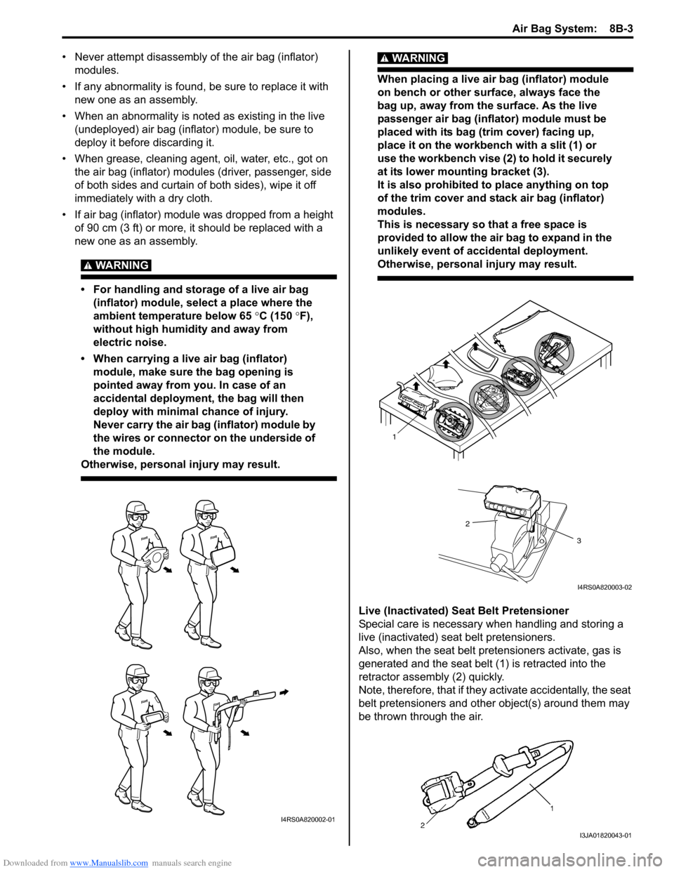
• Never attempt disassembly of the air bag (inflator) modules.
• If any abnormality is found, be sure to replace it with
new one as an assembly.
• When an abnormality is noted as existing in the live (undeployed) air bag (inflator) module, be sure to
deploy it before discarding it.
• When grease, cleaning agent, oil, water, etc., got on the air bag (inflator) modules (driver, passenger, side
of both sides and curtain of both sides), wipe it off
immediately with a dry cloth.
• If air bag (inflator) module was dropped from a height of 90 cm (3 ft) or more, it should be replaced with a
new one as an assembly.
WARNING!
• For handling and storage of a live air bag (inflator) module, select a place where the
ambient temperature below 65 °C (150 ° F),
without high humidity and away from
electric noise.
• When carrying a live air bag (inflator) module, make sure the bag opening is
pointed away from you. In case of an
accidental deployment, the bag will then
deploy with minimal chance of injury.
Never carry the air bag (inflator) module by
the wires or connector on the underside of
the module.
Otherwise, personal injury may result.
WARNING!
When placing a live air bag (inflator) module
on bench or other surface, always face the
bag up, away from the surface. As the live
passenger air bag (inflator) module must be
placed with its bag (trim cover) facing up,
place it on the workbench with a slit (1) or
use the workbench vise (2) to hold it securely
at its lower mounting bracket (3).
It is also prohibited to place anything on top
of the trim cover and stack air bag (inflator)
modules.
This is necessary so that a free space is
provided to allow the air bag to expand in the
unlikely event of accidental deployment.
Otherwise, personal injury may result.
Live (Inactivated) Seat Belt Pretensioner
Special care is necessary when handling and storing a
live (inactivated) seat belt pretensioners.
Also, when the seat belt pretensioners activate, gas is
generated and the seat belt (1) is retracted into the
retractor assembly (2) quickly.
Note, therefore, that if they activate accidentally, the seat
belt pretensioners and other object(s) around them may
be thrown through the air.
I4RS0A820002-01
1
2
3
I4RS0A820003-02
I3JA01820043-01
Page 1042 of 1496
Downloaded from www.Manualslib.com manuals search engine 8B-4 Air Bag System:
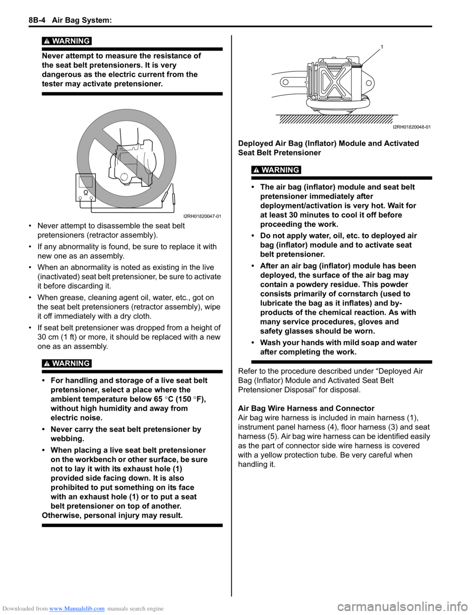
WARNING!
Never attempt to measure the resistance of
the seat belt pretensioners. It is very
dangerous as the electric current from the
tester may activate pretensioner.
• Never attempt to disassemble the seat belt
pretensioners (retractor assembly).
• If any abnormality is found, be sure to replace it with
new one as an assembly.
• When an abnormality is noted as existing in the live (inactivated) seat belt preten sioner, be sure to activate
it before discarding it.
• When grease, cleaning agent oil, water, etc., got on the seat belt pretensioners (r etractor assembly), wipe
it off immediately with a dry cloth.
• If seat belt pretensioner was dropped from a height of 30 cm (1 ft) or more, it should be replaced with a new
one as an assembly.
WARNING!
• For handling and storage of a live seat belt pretensioner, select a place where the
ambient temperature below 65 °C (150 ° F),
without high humidity and away from
electric noise.
• Never carry the seat belt pretensioner by webbing.
• When placing a live seat belt pretensioner on the workbench or other surface, be sure
not to lay it with its exhaust hole (1)
provided side facing down. It is also
prohibited to put something on its face
with an exhaust hole (1) or to put a seat
belt pretensioner on top of another.
Otherwise, personal injury may result.
Deployed Air Bag (Inflator) Module and Activated
Seat Belt Pretensioner
WARNING!
• The air bag (inflator) module and seat belt
pretensioner immediately after
deployment/activation is very hot. Wait for
at least 30 minutes to cool it off before
proceeding the work.
• Do not apply water, oil, etc. to deployed air bag (inflator) module and to activate seat
belt pretensioner.
• After an air bag (inflator) module has been deployed, the surface of the air bag may
contain a powdery residue. This powder
consists primarily of cornstarch (used to
lubricate the bag as it inflates) and by-
products of the chemical reaction. As with
many service procedures, gloves and
safety glasses should be worn.
• Wash your hands with mild soap and water after completing the work.
Refer to the procedure described under “Deployed Air
Bag (Inflator) Module and Activated Seat Belt
Pretensioner Disposal” for disposal.
Air Bag Wire Harness and Connector
Air bag wire harness is includ ed in main harness (1),
instrument panel harness (4), floor harness (3) and seat
harness (5). Air bag wire harness can be identified easily
as the part of connector side wire harness is covered
with a yellow protection tube. Be very careful when
handling it.
I2RH01820047-01
1
I2RH01820048-01
Page 1168 of 1496

Downloaded from www.Manualslib.com manuals search engine 9-ii Table of Contents
List of Connectors ........................................... 9A-103
C Connector .................................................... 9A-103
D Connector (M16A engine) ........................... 9A-104
E Connector .................................................... 9A-104
G Connector .................................................... 9A-106
J Connector ..................................................... 9A-108
K Connector .................................................... 9A-109
L Connector..................................................... 9A-109
M Connector (SPORT model) ......................... 9A-111
O Connector .................................................... 9A-111
R Connector .................................................... 9A-111
Lighting Systems .................................... 9B-1
Component Location ........... ................................9B-1
Lighting System Component s Location............... 9B-1
Interior Light System Location............................. 9B-2
Diagnostic Information and Procedures ............ 9B-2 Headlight Symptom Diagnosis ............................ 9B-2
Headlight Leveling System Symptom Diagnosis (If Equipped) ..................................... 9B-2
Turn Signal and Hazard Warning Light Symptom Diagnosis .......................................... 9B-3
Clearance, Tail and License Plate Light Symptom Diagnosis .......................................... 9B-3
Back-Up Light Symptom Diagnosis..................... 9B-4
Brake Light Symptom Diagnosis ......................... 9B-4
Front Fog Light Symptom Diagnosis (If Equipped) .......................................................... 9B-4
Interior Light Symptom Diagnosis ....................... 9B-5
Repair Instructions ..............................................9B-5 Headlight Housing Removal and Installation ...... 9B-5
Headlight Bulb Replacemen t............................... 9B-6
Headlight Aiming Adjustment with Screen .......... 9B-6
Headlight Switch (in Lighting Switch) Removal and Installation ................................... 9B-8
Headlight Switch (in Lighting Switch) Inspection .......................................................... 9B-8
Hazard Warning Switch Removal and Installation ......................................................... 9B-8
Hazard Warning Switch Inspection ..................... 9B-9
Brake Light Switch Inspection ............................. 9B-9
Turn Signal Light Switch (in Lighting Switch) Removal and Installation ................................... 9B-9
Turn Signal Light Switch (in Lighting Switch) Inspection .......................................................... 9B-9
Turn Signal and Hazard Warning Relay Removal and Installation ................................... 9B-9
Turn Signal and Hazard Warning Relay Inspection ........................................................ 9B-10
License Light Removal and Installation............. 9B-10
Front Fog Light Removal and Installation (If Equipped) ........................................................ 9B-11
Front Fog Light Bulb Replacement (If Equipped) ........................................................ 9B-11
Front Fog Light Switch Inspection (If Equipped) ........................................................ 9B-11
Front Fog Light Relay Inspection (If Equipped) ........................................................ 9B-11
Front Fog Light Aiming Adjustment with Screen (If Equipped) ....................................... 9B-12 Headlight Leveling Switch Inspection (If
Equipped) ........................................................ 9B-13
Headlight Leveling Actuator Inspection (If Equipped) ........................................................ 9B-13
Instrumentation / Driver Info. / Horn ...... 9C-1
Precautions ...........................................................9C-1 Precautions in Diagnosing Troubles for Combination Meter ............................................9C-1
General Description .............................................9C-1 CAN Communication System Description...........9C-1
Auto Volume Co ntrol System Description (If
Equipped) ..........................................................9C-3
Schematic and Routing Diagram ........................9C-4 Combination Meter Circuit Diagram ....................9C-4
Component Location ............ ...............................9C-6
Audio System Component Location ....................9C-6
Diagnostic Information and Procedures ............9C-6 Speedometer and VSS Symp tom Diagnosis ......9C-6
Tachometer Symptom Diagnosis ........................9C-6
Engine Coolant Temperature (ECT) Meter Symptom Diagnosis ..........................................9C-7
Fuel Meter Symptom Diagnosis ..........................9C-7
Low Fuel Warning Light Symptom Diagnosis .....9C-7
Oil Pressure Warning Light Symptom Diagnosis ..........................................................9C-8
Brake and Parking Brake Warning Light Symptom Diagnosis ..........................................9C-8
Seat Belt Reminder Light Symptom Diagnosis (If Equipped)......................................................9C-8
A/T Shift Position Indicator Symptom Diagnosis (A/T Model).......................................9C-9
Charge Warning Light Sy mptom Diagnosis ........9C-9
Main Beam (High Beam) Indicator Symptom Diagnosis ..........................................................9C-9
Warning Buzzer Circuit Sy mptom Diagnosis ....9C-10
Cigarette Lighter Symptom Diagnosis (If Equipped) ........................................................9C-10
Horn Symptom Diagnosis .................................9C-10
Information Display Symptom Diagnosis (If Equipped) ........................................................9C-11
Clock Symptom Diagnosis (If Equipped)...........9C-12
Audio System Symptom Diagnosis (If Equipped) ........................................................9C-12
Remote Audio Control Switch Symptom Diagnosis (If Equipped) ...................................9C-13
Navigation Symptom Diagnosis (If Equipped)...9C-14
Repair Instructions ............ ................................9C-14
Ignition Switch Removal and Installation...........9C-14
Ignition Switch Inspection..................................9C-14
Combination Meter Removal and Installation ...9C-15
Fuel Level Sensor Removal and Installation .....9C-15
Fuel Level Sensor Inspection ............................9C-15
Oil Pressure Switch Remova l and Installation ..9C-15
Oil Pressure Switch Inspec tion .........................9C-16
Engine Coolant Temperature (ECT) Sensor Inspection ........................................................9C-16
Brake Fluid Level Switch Inspection .................9C-16
Parking Brake Switch Inspec tion.......................9C-16