2005 SUZUKI SWIFT Cord inspection
[x] Cancel search: Cord inspectionPage 398 of 1496

Downloaded from www.Manualslib.com manuals search engine 1H-6 Ignition System:
Ignition Spark TestS7RS0B1804004
1) Remove air cleaner assembly with air intake pipe.
2) Disconnect all injector couplers from injectors.
WARNING!
Without disconnection of injector couplers,
combustible gas may come out from spark
plug holes during this test and may get
ignited in engine room.
3) Remove spark plug and check it for condition and
type referring to “Spark Plug Inspection”.
4) If OK, connect ignition coil coupler to ignition coil assembly and connect spark plug to ignition coil
assembly or high-tension cord. Ground spark plug. 5) Crank engine and check if each spark plug sparks.
6) If no spark is emitted, inspect the related parts as
described in “Ignition System Symptom Diagnosis”.
Repair Instructions
High-Tension Cord Removal and InstallationS7RS0B1806001
Removal
1) Remove air cleaner assembly with air intake pipe and cylinder head upper cover.
2) Disconnect No.1 cylinder (2) and No.3 cylinder (3)
high-tension cords from ignition coil assemblies (1)
while gripping each cap.
3) Pull out high-tension cords from spark plugs while gripping each cap.
CAUTION!
• Removal of high-tension cords together with clamps will be recommended so as
not to damage their inside wire (resistive
conductor).
• For the same reason, pull out each connection by gripping cap portion.
Installation
1) Install No.1 cylinder (2) and No.3 cylinder (3) high-
tension cords to spark plugs and ignition coil
assemblies (1) while gripping each cap.
CAUTION!
• Never attempt to use metal conductor high-tension cords as replacing parts.
• Insert each cap portion fully when installing high-tension cords.
I4RS0A180006-01
I4RS0A180003-01
I4RS0A180004-01
Page 399 of 1496

Downloaded from www.Manualslib.com manuals search engine Ignition System: 1H-7
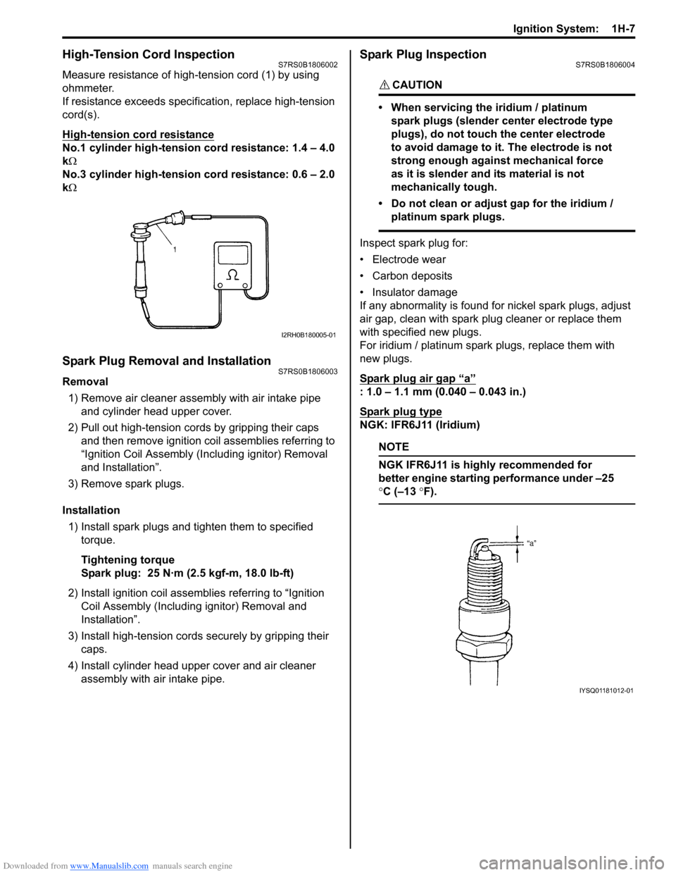
High-Tension Cord InspectionS7RS0B1806002
Measure resistance of high-tension cord (1) by using
ohmmeter.
If resistance exceeds specification, replace high-tension
cord(s).
High-tension cord resistance
No.1 cylinder high-tension cord resistance: 1.4 – 4.0
k Ω
No.3 cylinder high-tension cord resistance: 0.6 – 2.0
k Ω
Spark Plug Removal and InstallationS7RS0B1806003
Removal
1) Remove air cleaner assembly with air intake pipe and cylinder head upper cover.
2) Pull out high-tension cords by gripping their caps and then remove ignition coil assemblies referring to
“Ignition Coil Assembly (Inc luding ignitor) Removal
and Installation”.
3) Remove spark plugs.
Installation 1) Install spark plugs and tighten them to specified torque.
Tightening torque
Spark plug: 25 N·m (2.5 kgf-m, 18.0 lb-ft)
2) Install ignition coil assemblies referring to “Ignition Coil Assembly (Including ignitor) Removal and
Installation”.
3) Install high-tension cords securely by gripping their caps.
4) Install cylinder head upper cover and air cleaner assembly with air intake pipe.
Spark Plug InspectionS7RS0B1806004
CAUTION!
• When servicing the iridium / platinum
spark plugs (slender center electrode type
plugs), do not touch the center electrode
to avoid damage to it. The electrode is not
strong enough against mechanical force
as it is slender and its material is not
mechanically tough.
• Do not clean or adjust gap for the iridium / platinum spark plugs.
Inspect spark plug for:
• Electrode wear
• Carbon deposits
• Insulator damage
If any abnormality is found for nickel spark plugs, adjust
air gap, clean with spark plug cleaner or replace them
with specified new plugs.
For iridium / platinum spark plugs, replace them with
new plugs.
Spark plug air gap
“a”
: 1.0 – 1.1 mm (0.040 – 0.043 in.)
Spark plug type
NGK: IFR6J11 (Iridium)
NOTE
NGK IFR6J11 is highly recommended for
better engine starting performance under –25
°C (–13 °F).
I2RH0B180005-01
IYSQ01181012-01
Page 400 of 1496

Downloaded from www.Manualslib.com manuals search engine 1H-8 Ignition System:
Ignition Coil Assembly (Including ignitor)
Removal and Installation
S7RS0B1806005
Removal1) Disconnect negative (–) cable at battery.
2) Remove air cleaner assembly with air intake pipe and cylinder head upper cover.
3) Disconnect ignition coil coupler.
4) Disconnect high-tension cord (3) from ignition coil assembly (2).
5) Remove ignition coil bolts (1) and then pull out ignition coil assembly.
Installation 1) Install ignition coil assembly (2).
2) Tighten ignition coil bolts (1) to specified torque, and then connect igni tion coil coupler.
Tightening torque
Ignition coil bolt (a): 10 N·m (1.0 kgf-m, 7.5 lb-ft)
3) Install high-tension cord (3) to ignition coil assembly while gripping its cap.
4) Install cylinder head upper cover and air cleaner assembly with air intake pipe.
5) Connect negative (–) cable to battery.
Ignition Coil Assembly (Including ignitor)
Inspection
S7RS0B1806006
Measure secondary coil for resistance.
If resistance is out of specification, replace ignition coil
assembly.
Secondary coil resistance
7.5 – 10.3 k Ω at 20 °C, 68 ° F
Ignition Timing InspectionS7RS0B1806007
NOTE
• Ignition timing is not adjustable. If ignition
timing is out of specification, check
system related parts.
• Before starting engine, place transmission gear shift lever in “Neutral” (shift selector
lever to “P” range for A/T model), and set
parking brake.
1) Connect scan tool to DLC (1) with ignition switch OFF.
Special tool
(A): SUZUKI scan tool
2) Start engine and warm it up to normal operating temperature.
3) Make sure that all of electrical loads except ignition are switched off.
4) Check to be sure that idle speed is within specification referring to “Idle Speed and IAC
Throttle Valve Opening Inspection in Section 1A”
5) Fix ignition timing by using “Fixed Spark” of “Misc Test” mode on scan tool.
I2RH0B180006-01
I3RM0A180004-01
I2RH0B180007-01
(A)
1
I4RS0B180003-01
Page 518 of 1496

Downloaded from www.Manualslib.com manuals search engine 4B-2 Front Brakes:
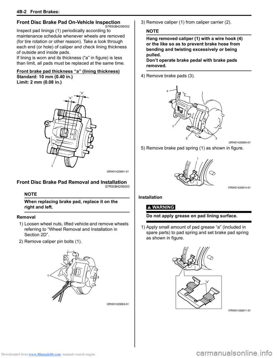
Front Disc Brake Pad On-Vehicle InspectionS7RS0B4206002
Inspect pad linings (1) periodically according to
maintenance schedule whenever wheels are removed
(for tire rotation or other reason). Take a look through
each end (or hole) of caliper and check lining thickness
of outside and inside pads.
If lining is worn and its thic kness (“a” in figure) is less
than limit, all pads must be replaced at the same time.
Front brake pad thickness “a” (lining thickness)
Standard: 10 mm (0.40 in.)
Limit: 2 mm (0.08 in.)
Front Disc Brake Pad Removal and InstallationS7RS0B4206003
NOTE
When replacing brake pad, replace it on the
right and left.
Removal
1) Loosen wheel nuts, lifted vehicle and remove wheels referring to “Wheel Remova l and Installation in
Section 2D”.
2) Remove caliper pin bolts (1). 3) Remove caliper (1) from caliper carrier (2).
NOTE
Hang removed caliper (1) with a wire hook (4)
or the like so as to prevent brake hose from
bending and twisting excessively or being
pulled.
Don’t operate brake pedal with brake pads
removed.
4) Remove brake pads (3).
5) Remove brake pad spring (1) as shown in figure.
Installation
WARNING!
Do not apply grease on pad lining surface.
1) Apply small amount of pad grease “a” (included in spare parts) to pad spring and set brake pad spring
as shown in figure.
I2RH01420001-01
1
I2RH01420003-01
I2RH01420004-01
1
I7RW01420014-01
"a"
I7RW01420011-01
Page 548 of 1496

Downloaded from www.Manualslib.com manuals search engine 4E-9 ABS:
Step 1: Malfunction Analysis
Customer complaint analysis
Record details of the problem (failure, complaint) and how it occurred as described by the customer.
For this purpose, use of such a questionnaire form as shown in the following will facilitate collec ting information to the
point required for proper analysis and diagnosis. Customer questionnaire (Example)
6
�) Check for intermittent problem
1) Check intermittent troubles referring to “Intermittent and
Poor Connection Inspection in Section 00” and related
circuit of trouble code recorded in Step 1.
Does trouble recur? Go to Step 4.
Go to Step 7.
7 �) Final confirmation test
1) Perform “Step 7: Final Confirmation Test: ”.
Does trouble recur? Go to Step 3.
End.
Step
Action YesNo
I2RH01450014-01
Page 549 of 1496

Downloaded from www.Manualslib.com manuals search engine ABS: 4E-10
Problem symptom confirmation
Check if what the customer claimed in “Customer
Questionnaire” is actually found in the vehicle and if that
symptom is found, whether it is identified as a failure.
(This step should be shared with the customer if
possible.) Check warning lights related to brake system
referring to “EBD Warning Light (Brake Warning Light)
Check” and “ABS Warning Light Check”.
DTC check, record and clearance
Perform “DTC Check” proced ure, record it and then
clear it referring to “DTC Clearance”.
Recheck DTC referring to “DTC Check”.
When DTC which is recorded at DTC check procedure is
detected again after performi ng DTC clearance, go to
“Step 4: ABS Check: ” to proceed the diagnosis.
When DTC which is recorded at DTC check procedure is
not indicated anymore after performing DTC clearance,
ABS control module does not perform the system
diagnosis, or temporary abnormality may occur,
therefore go to “Step 2: Driving Test: ” to proceed the
diagnosis.
Step 2: Driving Test
Test drive the vehicle at 40 km/h for more than a minute
and check if any trouble symptom (such as abnormal
lighting of ABS warn ing light) exists.
If the malfunction DTC is co nfirmed again at ignition
switch ON, driving test as described is not necessary.
Proceed to Step 3.
Step 3: DTC Check
Recheck DTC referring to “DTC Check”.
Step 4: ABS Check
According to ABS Check for the DTC confirmation in
Step 3, locate the cause of the trouble, namely in a
sensor, switch, wire harness, connector, actuator
assembly or other part and repair or replace faulty parts.
Step 5: Brakes Diagnosis
Check the parts or system suspected as a possible
cause referring to “Brakes Symptom Diagnosis in
Section 4A” and based on symptoms appearing on the
vehicle (symptom obtained through Steps 1 and 2 and
repair or replace faulty parts, if any).
Step 6: Check for Intermittent Problem
Check parts where an intermittent trouble is easy to
occur (e.g., wire harness, con nector, etc.), referring to
“Intermittent and Poor Connection Inspection in Section
00” and related circuit of trouble code recorded in Step 1
to 3.
Step 7: Final Confirmation Test
Confirm that the problem symptom has gone and the
ABS is free from any abnormal conditions. If what has
been repaired is related to the malfunction DTC, clear
the DTC once referring to “DTC Clearance” and perform
test driving and confirm that no DTC is indicated.ABS Warning Light CheckS7RS0B4504002
1) Turn ignition switch ON.
2) Check that ABS warning light (1) comes ON for
about 2 seconds and then goes off.
If any faulty condition is found, advance to “ABS
Warning Light Does Not Come ON at Ignition Switch
ON” or “ABS Warning Light Comes ON Steady”.
EBD Warning Light (Brake Warning Light)
Check
S7RS0B4504003
NOTE
Perform this check on a level place.
1) Turn ignition switch ON with parking brake applied.
2) Check that EBD warning lig ht (brake warning light)
(1) is turned ON.
3) Release parking brake with ignition switch ON and check that EBD warning lig ht (brake warning light)
goes off.
If it doesn’t go off, go to “EBD Warning Light (Brake
Warning Light) Comes ON Steady”.
11
I4RS0A450007-01
BRAKE
1
I4RS0A450008-01
Page 570 of 1496

Downloaded from www.Manualslib.com manuals search engine 4E-31 ABS:
2) Bleed air from brake system referring to “Air Bleeding of Brake System in Section 4A”.
3) Check each installed part for fluid leakage and perform “ABS Hydraulic Un it Operation Check”.
NOTE
For new ABS hydraulic unit / control module
assembly, if “ABS Hydraulic Unit Operation
Check” has not been performed, ABS
warning light may flash when ignition switch
is turned ON position.
Accordingly preform “ABS Hydraulic Unit
Operation Check” to stop flashing of ABS
warning light.
Front / Rear Wheel Speed Sensor On-Vehicle
Inspection
S7RS0B4506005
Output Voltage Inspection
1) Disconnect negative cable from battery.
2) Hoist vehicle a little.
3) Disconnect wheel speed sensor connector.
4) Disconnect wheel speed grommet from vehicle body.
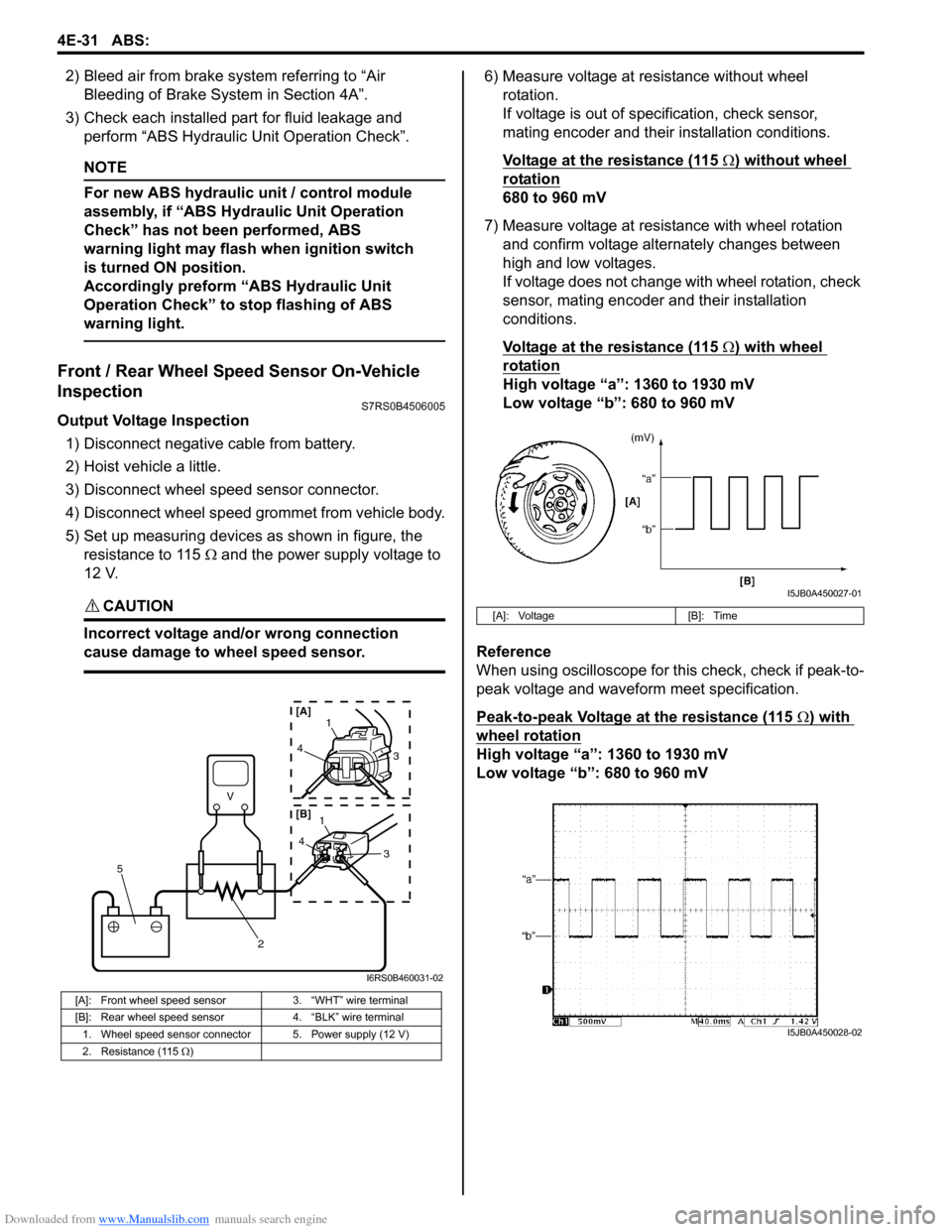
5) Set up measuring devices as shown in figure, the resistance to 115 Ω and the power supply voltage to
12 V.
CAUTION!
Incorrect voltage and/or wrong connection
cause damage to wheel speed sensor.
6) Measure voltage at resistance without wheel rotation.
If voltage is out of specification, check sensor,
mating encoder and their installation conditions.
Voltage at the resistance (115
Ω) without wheel
rotation
680 to 960 mV
7) Measure voltage at resistance with wheel rotation and confirm voltage alternately changes between
high and low voltages.
If voltage does not change with wheel rotation, check
sensor, mating encoder and their installation
conditions.
Voltage at the resistance (115
Ω) with wheel
rotation
High voltage “a”: 1360 to 1930 mV
Low voltage “b”: 680 to 960 mV
Reference
When using oscilloscope for this check, check if peak-to-
peak voltage and waveform meet specification.
Peak-to-peak Voltage at the resistance (115
Ω) with
wheel rotation
High voltage “a”: 1360 to 1930 mV
Low voltage “b”: 680 to 960 mV
[A]: Front wheel speed sensor 3. “WHT” wire terminal
[B]: Rear wheel speed sensor 4. “BLK” wire terminal
1. Wheel speed sensor connector 5. Power supply (12 V)
2. Resistance (115 Ω )
V
2
5
41
3
43
1
[A]
[B]
I6RS0B460031-02
[A]: Voltage [B]: Time
I5JB0A450027-01
I5JB0A450028-02
Page 586 of 1496

Downloaded from www.Manualslib.com manuals search engine 4F-12 Electronic Stability Program:
Diagnostic Information and Procedures
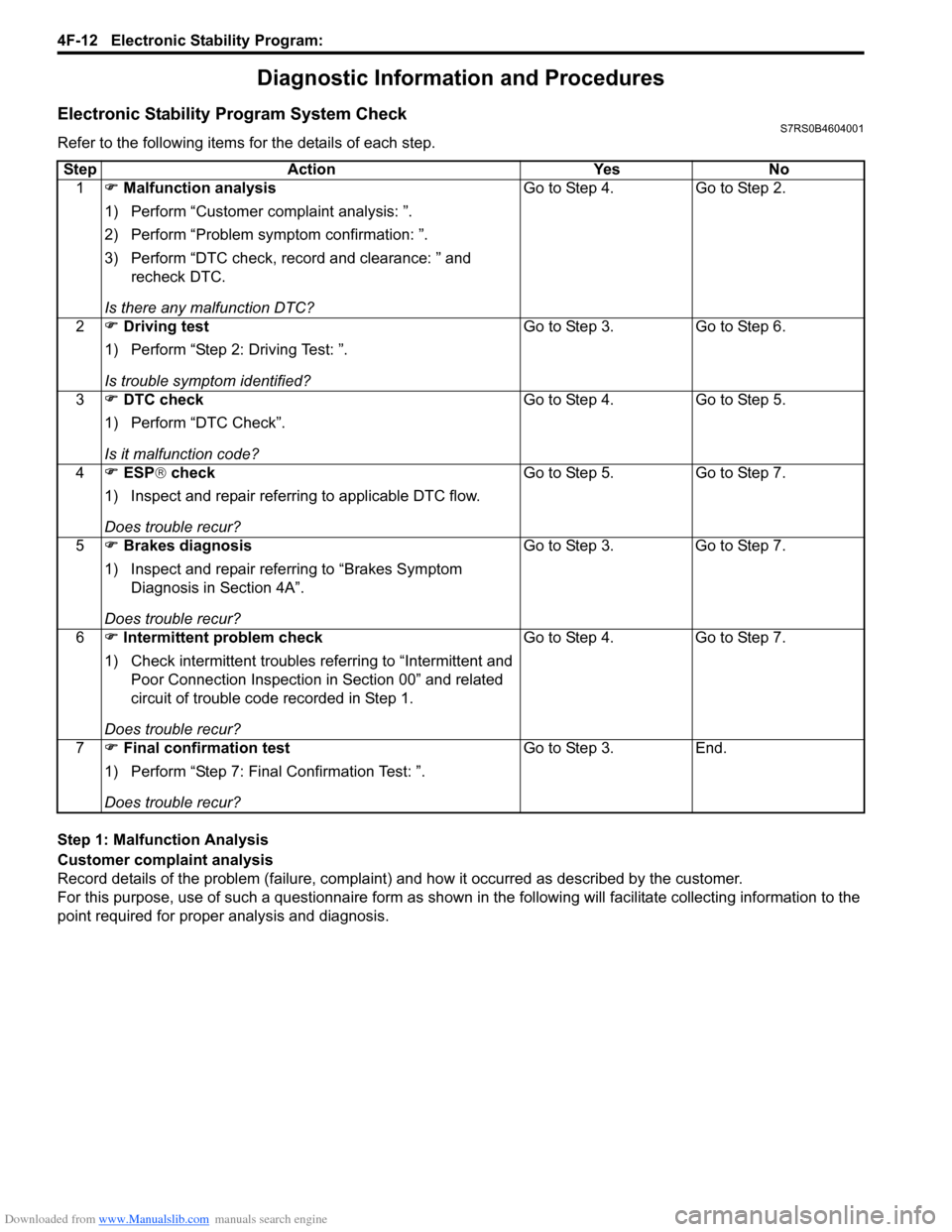
Electronic Stability Program System CheckS7RS0B4604001
Refer to the following items for the details of each step.
Step 1: Malfunction Analysis
Customer complaint analysis
Record details of the problem (failure, complaint) and how it occurred as described by the customer.
For this purpose, use of such a questionnaire form as shown in the following will facilitate collec ting information to the
point required for proper analysis and diagnosis. Step Action Yes No
1 �) Malfunction analysis
1) Perform “Customer complaint analysis: ”.
2) Perform “Problem symptom confirmation: ”.
3) Perform “DTC check, record and clearance: ” and recheck DTC.
Is there any malfunction DTC? Go to Step 4. Go to Step 2.
2 �) Driving test
1) Perform “Step 2: Driving Test: ”.
Is trouble symptom identified? Go to Step 3. Go to Step 6.
3 �) DTC check
1) Perform “DTC Check”.
Is it malfunction code? Go to Step 4. Go to Step 5.
4 �) ESP ® check
1) Inspect and repair referring to applicable DTC flow.
Does trouble recur? Go to Step 5. Go to Step 7.
5 �) Brakes diagnosis
1) Inspect and repair referring to “Brakes Symptom Diagnosis in Section 4A”.
Does trouble recur? Go to Step 3. Go to Step 7.
6 �) Intermittent problem check
1) Check intermittent troubles referring to “Intermittent and
Poor Connection Inspection in Section 00” and related
circuit of trouble code recorded in Step 1.
Does trouble recur? Go to Step 4. Go to Step 7.
7 �) Final confirmation test
1) Perform “Step 7: Final Confirmation Test: ”.
Does trouble recur? Go to Step 3. End.