2005 SUZUKI SWIFT bracket
[x] Cancel search: bracketPage 418 of 1496
Downloaded from www.Manualslib.com manuals search engine 1J-8 Charging System:
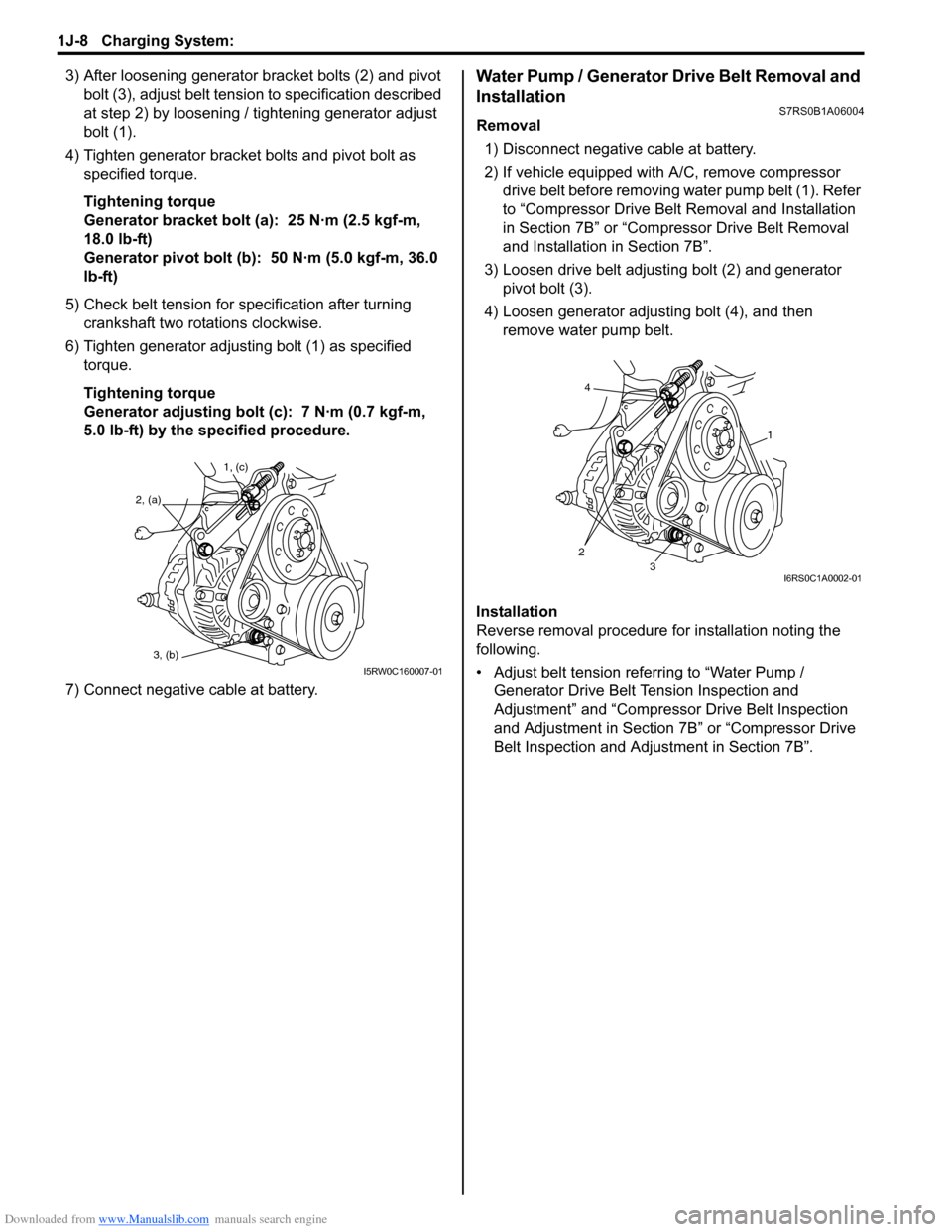
3) After loosening generator bracket bolts (2) and pivot bolt (3), adjust belt tensio n to specification described
at step 2) by loosening / tightening generator adjust
bolt (1).
4) Tighten generator bracket bolts and pivot bolt as specified torque.
Tightening torque
Generator bracket bolt (a): 25 N·m (2.5 kgf-m,
18.0 lb-ft)
Generator pivot bolt (b): 50 N·m (5.0 kgf-m, 36.0
lb-ft)
5) Check belt tension for specification after turning crankshaft two rotations clockwise.
6) Tighten generator adjusting bolt (1) as specified torque.
Tightening torque
Generator adjusting bolt (c): 7 N·m (0.7 kgf-m,
5.0 lb-ft) by the specified procedure.
7) Connect negative cable at battery.Water Pump / Generator Drive Belt Removal and
Installation
S7RS0B1A06004
Removal 1) Disconnect negative cable at battery.
2) If vehicle equipped with A/C, remove compressor drive belt before removing water pump belt (1). Refer
to “Compressor Drive Belt Removal and Installation
in Section 7B” or “Compr essor Drive Belt Removal
and Installation in Section 7B”.
3) Loosen drive belt adjusting bolt (2) and generator pivot bolt (3).
4) Loosen generator adjusting bolt (4), and then remove water pump belt.
Installation
Reverse removal procedure for installation noting the
following.
• Adjust belt tension referring to “Water Pump / Generator Drive Belt Tension Inspection and
Adjustment” and “Compressor Drive Belt Inspection
and Adjustment in Section 7B” or “Compressor Drive
Belt Inspection and Adjustment in Section 7B”.
1, (c)
2, (a)
3, (b)
I5RW0C160007-01
4
23
1
I6RS0C1A0002-01
Page 419 of 1496
Downloaded from www.Manualslib.com manuals search engine Charging System: 1J-9
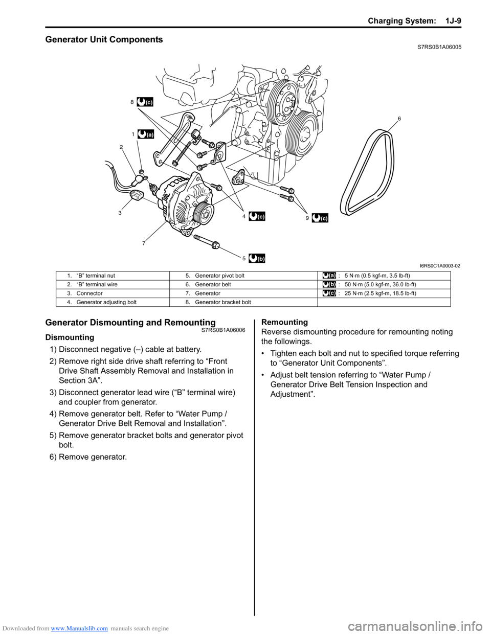
Generator Unit ComponentsS7RS0B1A06005
Generator Dismounting and RemountingS7RS0B1A06006
Dismounting1) Disconnect negative (–) cable at battery.
2) Remove right side drive shaft referring to “Front Drive Shaft Assembly Removal and Installation in
Section 3A”.
3) Disconnect generator lead wire (“B” terminal wire) and coupler from generator.
4) Remove generator belt. Refer to “Water Pump / Generator Drive Belt Re moval and Installation”.
5) Remove generator bracket bolts and generator pivot bolt.
6) Remove generator. Remounting
Reverse dismounting procedure for remounting noting
the followings.
• Tighten each bolt and nut to specified torque referring
to “Generator Unit Components”.
• Adjust belt tension referring to “Water Pump / Generator Drive Belt Tension Inspection and
Adjustment”.
(a)
(b)
(c)
1
2 8
3 7 5 49 6(c)
(c)
I6RS0C1A0003-02
1. “B” terminal nut
5. Generator pivot bolt : 5 N⋅m (0.5 kgf-m, 3.5 lb-ft)
2. “B” terminal wire 6. Generator belt : 50 N⋅m (5.0 kgf-m, 36.0 lb-ft)
3. Connector 7. Generator : 25 N⋅m (2.5 kgf-m, 18.5 lb-ft)
4. Generator adjusting bolt 8. Generator bracket bolt
Page 423 of 1496
Downloaded from www.Manualslib.com manuals search engine Charging System: 1J-13
Specifications
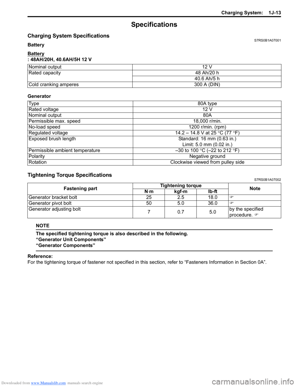
Charging System SpecificationsS7RS0B1A07001
Battery
Battery
: 48AH/20H, 40.6AH/5H 12 V
Generator
Tightening Torque SpecificationsS7RS0B1A07002
NOTE
The specified tightening torque is also described in the following.
“Generator Unit Components”
“Generator Components”
Reference:
For the tightening torque of fastener not specified in this section, refer to “Fasteners Information in Section 0A”.
Nominal output
12 V
Rated capacity 48 Ah/20 h
40.6 Ah/5 h
Cold cranking amperes 300 A (DIN)
Ty p e 80A type
Rated voltage 12 V
Nominal output 80A
Permissible max. speed 18,000 r/min.
No-load speed 1200 r/min. (rpm)
Regulated voltage 14.2 – 14.8 V at 25 ° C (77 °F)
Exposed brush length Standard: 16 mm (0.63 in.)
Limit: 5.0 mm (0.02 in.)
Permissible ambient temperature –30 to 100 °C (–22 to 212 °F)
Polarity Negative ground
Rotation Clockwise viewed from pulley side
Fastening partTightening torque
Note
N ⋅mkgf-mlb-ft
Generator bracket bolt 25 2.5 18.0 �)
Generator pivot bolt 50 5.0 36.0 �)
Generator adjusting bolt 70.7 5.0by the specified
procedure.
�)
Page 437 of 1496
Downloaded from www.Manualslib.com manuals search engine Front Suspension: 2B-4
Reference Information
Side slip
When checked with side slip tester, side slip should
satisfy following specification.Side slip
0 to IN 3.0 mm/m (0 to IN 0.118 in/3.3 ft)
If side slip is greatly di
fferent, toe or front wheel
alignment may not be correct.
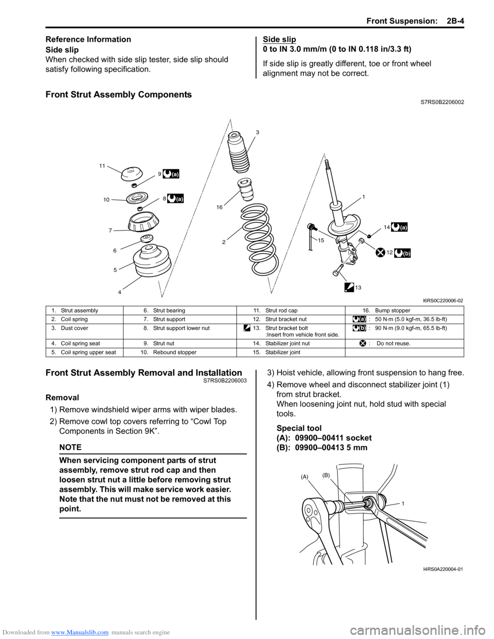
Front Strut Assembly ComponentsS7RS0B2206002
Front Strut Assembly Removal and InstallationS7RS0B2206003
Removal
1) Remove windshield wipe r arms with wiper blades.
2) Remove cowl top covers referring to “Cowl Top
Components in Section 9K”.
NOTE
When servicing component parts of strut
assembly, remove stru t rod cap and then
loosen strut nut a little before removing strut
assembly. This will make service work easier.
Note that the nut must not be removed at this
point.
3) Hoist vehicle, allowing front suspension to hang free.
4) Remove wheel and disconn ect stabilizer joint (1)
from strut bracket.
When loosening joint nu t, hold stud with special
tools.
Special tool
(A): 09900–00411 socket
(B): 09900–00413 5 mm
11 3
2 1
12
13
4
5
6
7
10
8(a)
(b)
9
(a)
14
15(a)
16
I6RS0C220006-02
1. Strut assembly
6. Strut bearing 11. Strut rod cap16. Bump stopper
2. Coil spring 7. Strut support 12. Strut bracket nut : 50 N⋅m (5.0 kgf-m, 36.5 lb-ft)
3. Dust cover 8. Strut support lower nut 13. Strut bracket bolt
:Insert from vehicle front side. : 90 N
⋅m (9.0 kgf-m, 65.5 lb-ft)
4. Coil spring seat 9. Strut nut 14. Stabilizer joint nut : Do not reuse.
5. Coil spring upper seat 10. Rebound stopper 15. Stabilizer joint
1
(A)
(B)
I4RS0A220004-01
Page 438 of 1496
Downloaded from www.Manualslib.com manuals search engine 2B-5 Front Suspension:
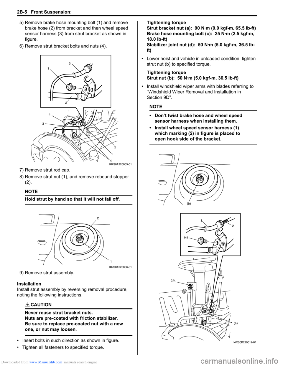
5) Remove brake hose mounting bolt (1) and remove brake hose (2) from bracket and then wheel speed
sensor harness (3) from strut bracket as shown in
figure.
6) Remove strut bracket bolts and nuts (4).
7) Remove strut rod cap.
8) Remove strut nut (1), and remove rebound stopper (2).
NOTE
Hold strut by hand so th at it will not fall off.
9) Remove strut assembly.
Installation
Install strut assembly by reversing removal procedure,
noting the following instructions.
CAUTION!
Never reuse strut bracket nuts.
Nuts are pre-coated with friction stabilizer.
Be sure to replace pre-coated nut with a new
one, or nut may loosen.
• Insert bolts in such direction as shown in figure.
• Tighten all fasteners to specified torque. Tightening torque
Strut bracket nut (a): 90 N·m (9.0 kgf-m, 65.5 lb-ft)
Brake hose mounting bolt (c): 25 N·m (2.5 kgf-m,
18.0 lb-ft)
Stabilizer joint nut (d): 50 N·m (5.0 kgf-m, 36.5 lb-
ft)
• Lower hoist and vehicle in unloaded condition, tighten strut nut (b) to specified torque.
Tightening torque
Strut nut (b): 50 N·m (5.0 kgf-m, 36.5 lb-ft)
• Install windshield wiper arms with blades referring to
“Windshield Wiper Removal and Installation in
Section 9D”.
NOTE
• Don’t twist brake hose and wheel speed sensor harness when installing them.
• Install wheel speed sensor harness (1) which marking (2) in figure is placed to
open hook side of the bracket.
1 3
2
2
1
4
4
3
I4RS0A220005-01
2
1
I4RS0A220006-01
(d) (a)
(b)
(c)
1
2
I4RS0B220012-01
Page 440 of 1496
Downloaded from www.Manualslib.com manuals search engine 2B-7 Front Suspension:
3) Install bump stopper onto strut rod. For installing
direction, refer to the figure in “Front Suspension
Construction”.
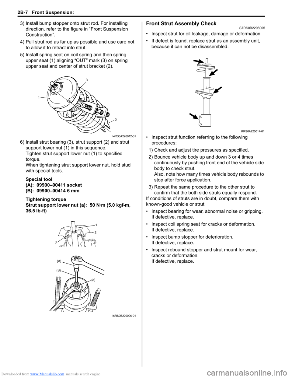
4) Pull strut rod as far up as possible and use care not to allow it to re tract into strut.
5) Install spring seat on coil spring and then spring upper seat (1) aligning “OUT” mark (3) on spring
upper seat and center of strut bracket (2).
6) Install strut bearing (3), strut support (2) and strut
support lower nut (1) in this sequence.
Tighten strut support lower nut (1) to specified
torque.
When tightening strut support lower nut, hold stud
with special tools.
Special tool
(A): 09900–00411 socket
(B): 09900–00414 6 mm
Tightening torque
Strut support lower nut (a): 50 N·m (5.0 kgf-m,
36.5 lb-ft)Front Strut Assembly CheckS7RS0B2206005
• Inspect strut for oil leakage, damage or deformation.
• If defect is found, replace strut as an assembly unit, because it can not be disassembled.
• Inspect strut function re ferring to the following
procedures:
1) Check and adjust tire pressures as specified.
2) Bounce vehicle body up and down 3 or 4 times continuously by pushing front end of the vehicle side
body to check strut.
Also, note how many times vehicle body rebounds to
stop after force application.
3) Repeat the same procedure to the other strut to confirm that the both side struts equally respond.
If conditions of struts are in doubt, compare them with
known-good vehicle or strut.
• Inspect bearing for wear, abnormal noise or gripping. If defective, replace.
• Inspect coil spring seat for cracks or deformation.
If defective, replace.
• Inspect bump stopper for deterioration. If defective, replace.
• Inspect rebound stopper and strut mount for wear, cracks or deformation.
If defective, replace.
I4RS0A220012-01
I6RS0B220006-01
I4RS0A220014-01
Page 442 of 1496
Downloaded from www.Manualslib.com manuals search engine 2B-9 Front Suspension:
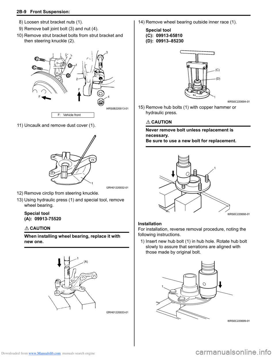
8) Loosen strut bracket nuts (1).
9) Remove ball joint bolt (3) and nut (4).
10) Remove strut bracket bolt s from strut bracket and
then steering knuckle (2).
11) Uncaulk and remove dust cover (1).
12) Remove circlip from steering knuckle.
13) Using hydraulic press (1) and special tool, remove wheel bearing.
Special tool
(A): 09913-75520
CAUTION!
When installing wheel bearing, replace it with
new one.
14) Remove wheel bearing outside inner race (1).
Special tool
(C): 09913-65810
(D): 09913–85230
15) Remove hub bolts (1) with copper hammer or hydraulic press.
CAUTION!
Never remove bolt unle ss replacement is
necessary.
Be sure to use a new bolt for replacement.
Installation
For installation, reverse removal procedure, noting the
following instructions.
1) Insert new hub bolt (1) in hub hole. Rotate hub bolt slowly to assure that serrations are aligned with
those made by original bolt.
F: Vehicle front
I4RS0B220013-01
I2RH01220032-01
I2RH01220033-01
I6RS0C220004-01
1
I6RS0C220008-01
1
I6RS0C220009-01
Page 444 of 1496
Downloaded from www.Manualslib.com manuals search engine 2B-11 Front Suspension:
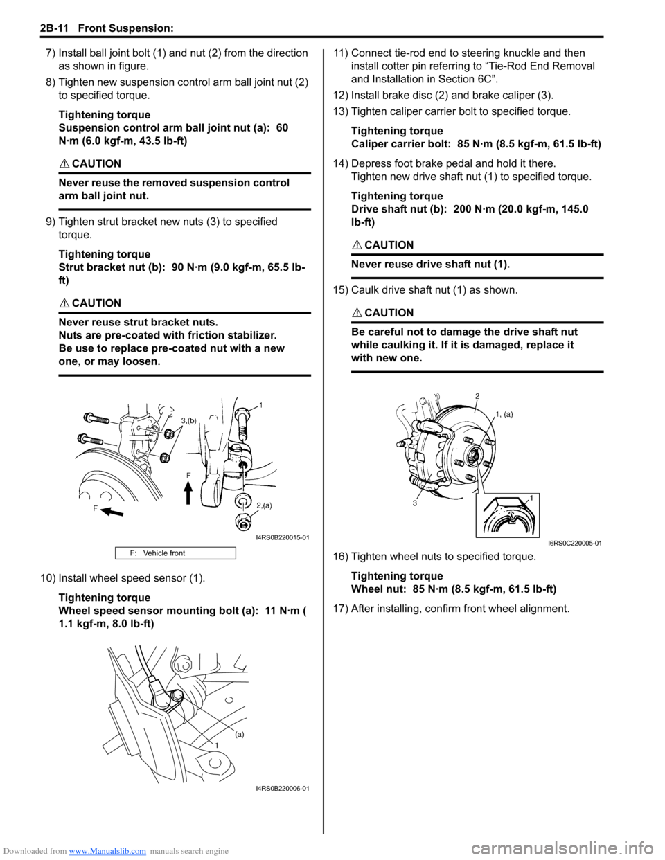
7) Install ball joint bolt (1) and nut (2) from the direction
as shown in figure.
8) Tighten new suspension co ntrol arm ball joint nut (2)
to specified torque.
Tightening torque
Suspension control arm ball joint nut (a): 60
N·m (6.0 kgf-m, 43.5 lb-ft)
CAUTION!
Never reuse the removed suspension control
arm ball joint nut.
9) Tighten strut bracket new nuts (3) to specified torque.
Tightening torque
Strut bracket nut (b): 90 N·m (9.0 kgf-m, 65.5 lb-
ft)
CAUTION!
Never reuse strut bracket nuts.
Nuts are pre-coated with friction stabilizer.
Be use to replace pre-coated nut with a new
one, or may loosen.
10) Install wheel speed sensor (1).
Tightening torque
Wheel speed sensor mounting bolt (a): 11 N·m (
1.1 kgf-m, 8.0 lb-ft) 11) Connect tie-rod end to steering knuckle and then
install cotter pin referrin g to “Tie-Rod End Removal
and Installation in Section 6C”.
12) Install brake disc (2) and brake caliper (3).
13) Tighten caliper carrier bolt to specified torque.
Tightening torque
Caliper carrier bolt: 85 N·m (8.5 kgf-m, 61.5 lb-ft)
14) Depress foot brake pedal and hold it there. Tighten new drive shaft nut (1) to specified torque.
Tightening torque
Drive shaft nut (b): 200 N·m (20.0 kgf-m, 145.0
lb-ft)
CAUTION!
Never reuse drive shaft nut (1).
15) Caulk drive shaft nut (1) as shown.
CAUTION!
Be careful not to damage the drive shaft nut
while caulking it. If it is damaged, replace it
with new one.
16) Tighten wheel nuts to specified torque.
Tightening torque
Wheel nut: 85 N·m (8.5 kgf-m, 61.5 lb-ft)
17) After installing, confirm front wheel alignment.F: Vehicle front
I4RS0B220015-01
1 (a)
I4RS0B220006-01
I6RS0C220005-01