Page 349 of 1496

Downloaded from www.Manualslib.com manuals search engine Engine Mechanical: 1D-64
Honing or Reboring Cylinders1) When any cylinder needs reboring, all other cylinders must also be rebored at the same time.
2) Select oversized piston according to amount of cylinder wear.
Oversize piston specification
Oversize 0.50: 78.453 – 78.468 mm (3.0887 –
3.0893 in.)
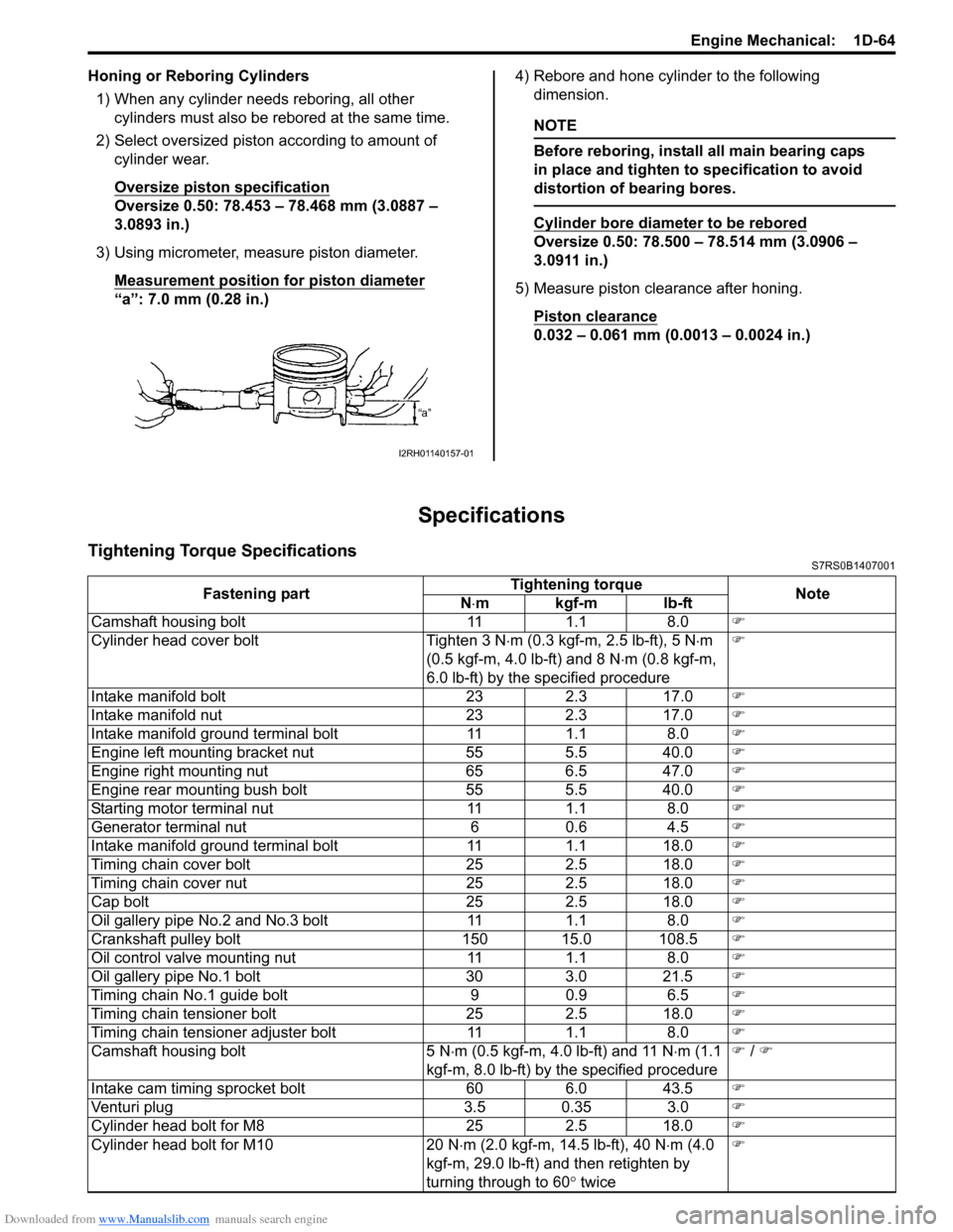
3) Using micrometer, measure piston diameter. Measurement position for piston diameter
“a”: 7.0 mm (0.28 in.) 4) Rebore and hone cylinder to the following
dimension.
NOTE
Before reboring, install all main bearing caps
in place and tighten to specification to avoid
distortion of bearing bores.
Cylinder bore diameter to be rebored
Oversize 0.50: 78.500 – 78.514 mm (3.0906 –
3.0911 in.)
5) Measure piston clearance after honing. Piston clearance
0.032 – 0.061 mm (0.0013 – 0.0024 in.)
Specifications
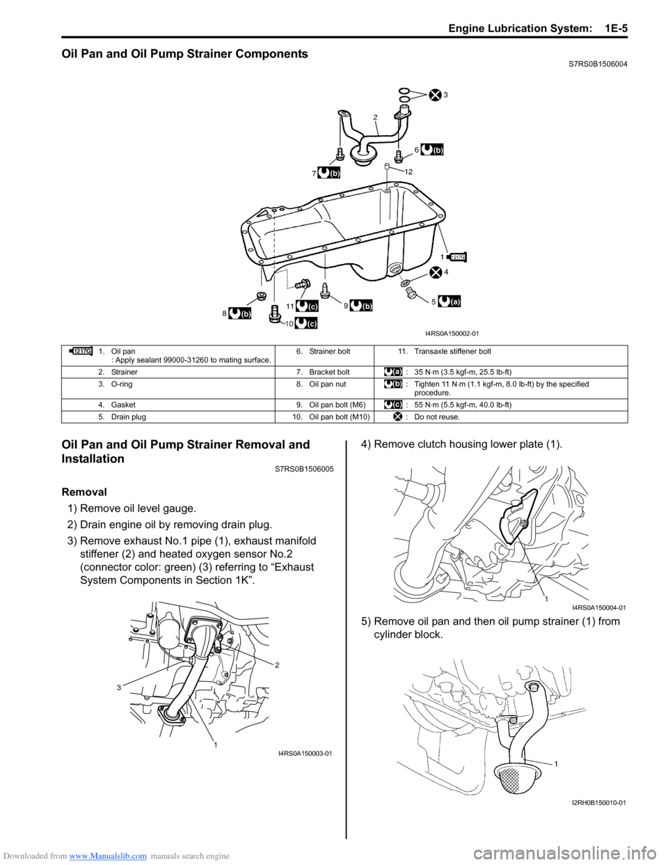
Tightening Torque SpecificationsS7RS0B1407001
I2RH01140157-01
Fastening part Tightening torque
Note
N ⋅mkgf-mlb-ft
Camshaft housing bolt 11 1.1 8.0 �)
Cylinder head cover bolt Tighten 3 N ⋅m (0.3 kgf-m, 2.5 lb-ft), 5 N ⋅m
(0.5 kgf-m, 4.0 lb-ft) and 8 N ⋅m (0.8 kgf-m,
6.0 lb-ft) by the specified procedure �)
Intake manifold bolt 23 2.3 17.0 �)
Intake manifold nut 23 2.3 17.0 �)
Intake manifold ground terminal bolt 11 1.1 8.0 �)
Engine left mounting bracket nut 55 5.5 40.0 �)
Engine right mounting nut 65 6.5 47.0 �)
Engine rear mounting bush bolt 55 5.5 40.0 �)
Starting motor terminal nut 11 1.1 8.0 �)
Generator terminal nut 6 0.6 4.5 �)
Intake manifold ground terminal bolt 11 1.1 18.0 �)
Timing chain cover bolt 25 2.5 18.0 �)
Timing chain cover nut 25 2.5 18.0 �)
Cap bolt 25 2.5 18.0 �)
Oil gallery pipe No.2 and No.3 bolt 11 1.1 8.0 �)
Crankshaft pulley bolt 150 15.0 108.5 �)
Oil control valve mounting nut 11 1.1 8.0 �)
Oil gallery pipe No.1 bolt 30 3.0 21.5 �)
Timing chain No.1 guide bolt 9 0.9 6.5 �)
Timing chain tensioner bolt 25 2.5 18.0 �)
Timing chain tensioner adjuster bolt 11 1.1 8.0 �)
Camshaft housing bolt 5 N ⋅m (0.5 kgf-m, 4.0 lb-ft) and 11 N ⋅m (1.1
kgf-m, 8.0 lb-ft) by the specified procedure �)
/ �)
Intake cam timing sprocket bolt 60 6.0 43.5 �)
Venturi plug 3.5 0.35 3.0 �)
Cylinder head bolt for M8 25 2.5 18.0 �)
Cylinder head bolt for M10 20 N ⋅m (2.0 kgf-m, 14.5 lb-ft), 40 N ⋅m (4.0
kgf-m, 29.0 lb-ft) and then retighten by
turning through to 60 ° twice �)
Page 357 of 1496

Downloaded from www.Manualslib.com manuals search engine Engine Lubrication System: 1E-5
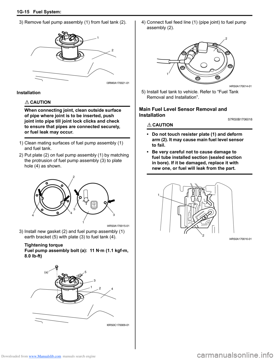
Oil Pan and Oil Pump Strainer ComponentsS7RS0B1506004
Oil Pan and Oil Pump Strainer Removal and
Installation
S7RS0B1506005
Removal1) Remove oil level gauge.
2) Drain engine oil by removing drain plug.
3) Remove exhaust No.1 pipe (1), exhaust manifold stiffener (2) and heated oxygen sensor No.2
(connector color: green) (3) referring to “Exhaust
System Components in Section 1K”. 4) Remove clutch housing lower plate (1).
5) Remove oil pan and then oil pump strainer (1) from
cylinder block.
I4RS0A150002-01
1. Oil pan : Apply sealant 99000-31260 to mating surface. 6. Strainer bolt 11. Transaxle stiffener bolt
2. Strainer 7. Bracket bolt : 35 N ⋅m (3.5 kgf-m, 25.5 lb-ft)
3. O-ring 8. Oil pan nut : Tighten 11 N ⋅m (1.1 kgf-m, 8.0 lb-ft) by the specified
procedure.
4. Gasket 9. Oil pan bolt (M6) : 55 N ⋅m (5.5 kgf-m, 40.0 lb-ft)
5. Drain plug 10. Oil pan bolt (M10) : Do not reuse.
2
1
3
I4RS0A150003-01
1I4RS0A150004-01
I2RH0B150010-01
Page 358 of 1496
Downloaded from www.Manualslib.com manuals search engine 1E-6 Engine Lubrication System:
Installation1) Install new O-rings (2) in the position as shown in figure and install o il pump strainer (1).
Tighten strainer bolt (3) first and then bracket bolt (4)
to specified torque.
Tightening torque
Oil pump strainer bolt (a): 11 N·m (1.1 kgf-m, 8.0
lb-ft)
Oil pump strainer bracket bolt (b): 11 N·m (1.1
kgf-m, 8.0 lb-ft)
2) Install dowel pin (1) to oil pan. 3) Apply sealant continuously to oil pan mating surface
as shown in figure.
“A”: Sealant 99000–31260 (SUZUKI Bond
No.1217G)
Sealant amount for oil pan
Width “a”: 3 mm (0.12 in.)
Height “b”: 2 mm (0.08 in.)
4) Install oil pan to cy linder block temporarily.
5) Insert dowel pin (1) in hole (2) of oil pan in order to
locate oil pan precisely.
NOTE
Dowel pin is available as a spare part (part
number: 04211–13189).
I2RH0B150012-01
I4RS0A150005-01
I4RS0A150006-01
21I4RS0A150007-01
Page 363 of 1496

Downloaded from www.Manualslib.com manuals search engine Engine Lubrication System: 1E-11
Specifications
Tightening Torque SpecificationsS7RS0B1507001
NOTE
The specified tightening torque is also described in the following.
“Heat Exchanger Components”
“Oil Pan and Oil Pump Strainer Components”
“Oil Pump Components”
Reference:
For the tightening torque of fastener not specified in this section, refer to “Fasteners Information in Section 0A”.
Special Tools and Equipment
Recommended Service MaterialS7RS0B1508001
NOTE
Required service material is also described in the following.
“Heat Exchanger Components”
“Oil Pan and Oil Pump Strainer Components”
“Oil Pump Components”
Special ToolS7RS0B1508002
Fastening part Tightening torque
Note
N ⋅mkgf-mlb-ft
Oil pressure switch 13 1.3 9.5 �)
Heat exchanger stand bolt 22 2.2 16.0 �)
Oil pump strainer bolt 11 1.1 8.0 �)
Oil pump strainer bracket bolt 11 1.1 8.0 �)
Oil pan bolt (M6) 11 1.1 8.0 �)
Oil pan bolt (M10) 55 5.5 40.0 �)
Oil pan nut 11 1.1 8.0 �)
Oil pan drain plug 35 3.5 25.5 �)
Transaxle stiffener bolt 55 5.5 40.0 �)
Oil pump rotor plate bolt 11 1.1 8.0 �)
MaterialSUZUKI recommended product or Specification Note
Sealant SUZUKI Bond No.1217G P/No.: 99000–31260�)
09915–77310 09915–78211
Oil pressure gauge (0-10kg/
cm2) Oil pressure gauge
attachment
�)�)
Page 390 of 1496

Downloaded from www.Manualslib.com manuals search engine 1G-15 Fuel System:
3) Remove fuel pump assembly (1) from fuel tank (2).
Installation
CAUTION!
When connecting joint, clean outside surface
of pipe where joint is to be inserted, push
joint into pipe till jo int lock clicks and check
to ensure that pipes are connected securely,
or fuel leak may occur.
1) Clean mating surfaces of fuel pump assembly (1) and fuel tank.
2) Put plate (2) on fuel pump assembly (1) by matching the protrusion of fuel pump assembly (3) to plate
hole (4) as shown.
3) Install new gasket (2) and fuel pump assembly (1) earth bracket (5) with plate (3) to fuel tank (4).
Tightening torque
Fuel pump assembly bolt (a): 11 N·m (1.1 kgf-m,
8.0 lb-ft) 4) Connect fuel feed line (1) (pipe joint) to fuel pump
assembly (2).
5) Install fuel tank to vehi cle. Refer to “Fuel Tank
Removal and Installation”.
Main Fuel Level Sensor Removal and
Installation
S7RS0B1706018
CAUTION!
• Do not touch resister plate (1) and deform arm (2). It may cause main fuel level sensor
to fail.
• Be very careful not to cause damage to fuel tube installed section (sealed section
in bore). If it be damaged, replace it with
new one, or fuel will leak from the part.
1
2
I3RM0A170021-01
3
1
3
2
44
I4RS0A170015-01
3
1 2
(a)
4
5
I6RS0C170009-01
2
1
I4RS0A170014-01
1
2I4RS0A170016-01
Page 405 of 1496
Downloaded from www.Manualslib.com manuals search engine Starting System: 1I-4
Repair Instructions
Starting Motor Dismounting and RemountingS7RS0B1906001
Dismounting1) Disconnect negative (–) battery lead at battery.
2) Disconnect magnetic switch lead wire (1) and battery cable (2) from starting motor terminals.
3) Detach shift & select control cable bracket from transaxle. (M/T model only)
4) Remove starting motor mount bolt (3) and nut (4).
5) Remove starting motor (5).
Remounting
Reverse the dismounting procedure noting the following.
• Tighten battery cable nut (6) to specified torque.
Tightening torque
Starting motor battery cable nut (a): 9.8 N·m (0.98 kgf-m, 7.0 lb-ft)
I4RS0A190002-01
: 9.8 N ⋅m (0.98 kgf-m, 7.0 lb-ft)
Page 406 of 1496
Downloaded from www.Manualslib.com manuals search engine 1I-5 Starting System:
Starting Motor ComponentsS7RS0B1906002
I4RS0A190003-01
1. Front housing 7. Plate 13. Planetary gear 19. Rear bush
2. Bush 8. Seal rubber 14. Packing 20. Starting motor battery cable nut
3. Pinion stop ring 9. Magnetic switch 15. Yoke :9.8 N
⋅m (0.98 kgf-m, 7.0 lb-ft)
4. Over-running clutch 10. Ball 16. Armature: Do not reuse.
5. Lever 11. Internal gear 17. Brush assembly : Apply grease 99000-25010 to sliding surface of each part.
6. Plunger 12. Planetary carrier shaft 18. Rear bracket
Page 407 of 1496

Downloaded from www.Manualslib.com manuals search engine Starting System: 1I-6
Starting Motor InspectionS7RS0B1906003
Plunger
Inspect plunger for wear. Replace if necessary.
Magnetic Switch
Push in plunger and release it. The plunger should
return quickly to its original position. Replace if
necessary.
Pull-in coil open circuit test
Check for continuity across magnetic switch “S” terminal
(1) and “M” terminal (2). If no continuity, coil is open and
should be replaced. Hold-in coil open circuit test
Check for continuity across ma
gnetic switch “S” terminal
(1) and coil case. If no continuity, coil is open and should
be replaced.
Rear Bracket Bush
Inspect bush for wear or damage. Replace if necessary.
Brush
• Check brushes for wear. Measure length of brushes and if below the limit,
replace the brush.
Brush length
Standard: 12.3 mm (0.48 in.)
Limit: 7.0 mm (0.28 in.)
• Install brushes to each brush holder and check for smooth movement.
I2RH01190008-01
I2RH01190009-01
I2RH01190010-01
I2RH01190011-01
I2RH01190012-01
I2RH01190013-01