2005 SUZUKI SWIFT Rack end
[x] Cancel search: Rack endPage 638 of 1496
Downloaded from www.Manualslib.com manuals search engine 4F-64 Electronic Stability Program:
Removal1) Disconnect negative (–) cable at battery.
2) Remove front console box referring to “Console Box Components in Section 9H”.
3) Disconnect connector from yaw rate / G sensor
assembly.
4) Remove yaw rate / G sens or assembly from sensor
bracket.
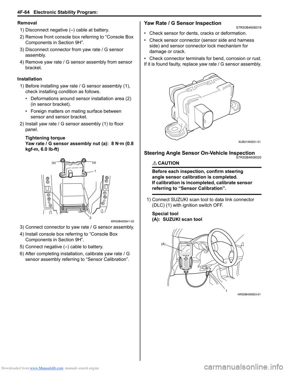
Installation 1) Before installing yaw rate / G sensor assembly (1),
check installing condition as follows.
• Deformations around sensor installation area (2) (in sensor bracket).
• Foreign matters on mating surface between sensor and sensor bracket.
2) Install yaw rate / G sensor assembly (1) to floor panel.
Tightening torque
Yaw rate / G sensor assembly nut (a): 8 N·m (0.8
kgf-m, 6.0 lb-ft)
3) Connect connector to yaw rate / G sensor assembly.
4) Install console box referring to “Console Box Components in Section 9H”.
5) Connect negative (–) cable to battery.
6) After completing installation, calibrate yaw rate / G
sensor assembly referring to “Sensor Calibration”.Yaw Rate / G Sensor InspectionS7RS0B4606019
• Check sensor for dents, cracks or deformation.
• Check sensor connector (sensor side and harness
side) and sensor connector lock mechanism for
damage or crack.
• Check connector terminals for bend, corrosion or rust.
If it is found faulty, replace yaw rate / G sensor assembly.
Steering Angle Sensor On-Vehicle InspectionS7RS0B4606020
CAUTION!
Before each inspection, confirm steering
angle sensor calibration is completed.
If calibration is incompleted, calibrate sensor
referring to “Sensor Calibration”.
1) Connect SUZUKI scan tool to data link connector
(DLC) (1) with ignition switch OFF.
Special tool
(A): SUZUKI scan tool
(a)
1
(a)
2I6RS0B460041-02
I6JB01460031-01
(A)
1
I4RS0B450003-01
Page 639 of 1496
Downloaded from www.Manualslib.com manuals search engine Electronic Stability Program: 4F-65
2) Turn ignition switch to ON position and select menu
“DATA LIST” mode of SUZUKI scan tool.
Refer to scan tool operator's manual for further
derails.
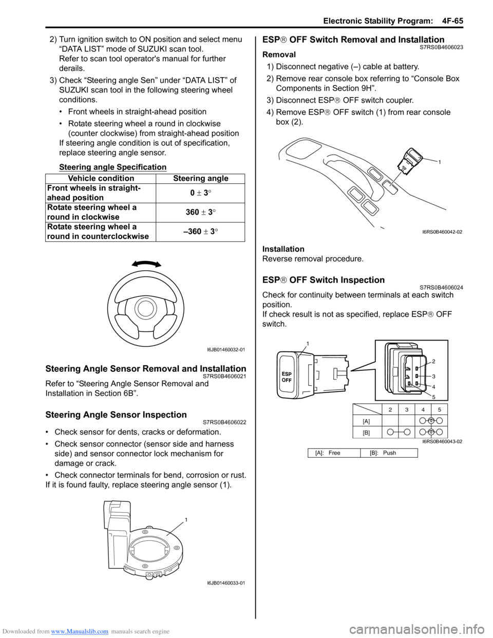
3) Check “Steering angle Sen” under “DATA LIST” of SUZUKI scan tool in th e following steering wheel
conditions.
• Front wheels in straight-ahead position
• Rotate steering wheel a round in clockwise (counter clockwise) from straight-ahead position
If steering angle condition is out of specification,
replace steering angle sensor.
Steering angle Specification
Steering Angle Sensor Removal and InstallationS7RS0B4606021
Refer to “Steering Angle Sensor Removal and
Installation in Section 6B”.
Steering Angle Sensor InspectionS7RS0B4606022
• Check sensor for dents, cracks or deformation.
• Check sensor connector (sensor side and harness
side) and sensor connector lock mechanism for
damage or crack.
• Check connector terminals for bend, corrosion or rust.
If it is found faulty, replace steering angle sensor (1).
ESP ® OFF Switch Removal and InstallationS7RS0B4606023
Removal
1) Disconnect negative (–) cable at battery.
2) Remove rear console box referring to “Console Box Components in Section 9H”.
3) Disconnect ESP ® OFF switch coupler.
4) Remove ESP ® OFF switch (1) from rear console
box (2).
Installation
Reverse removal procedure.
ESP ® OFF Switch InspectionS7RS0B4606024
Check for continuity between terminals at each switch
position.
If check result is not as specified, replace ESP ® OFF
switch.
Vehicle condition Steering angle
Front wheels in straight-
ahead position 0
± 3 °
Rotate steering wheel a
round in clockwise 360
± 3°
Rotate steering wheel a
round in counterclockwise –360
± 3 °
I6JB01460032-01
1
I6JB01460033-01
[A]: Free [B]: Push
1
I6RS0B460042-02
[A]
[B]2345
2
3
4
1
5
I6RS0B460043-02
Page 643 of 1496
Downloaded from www.Manualslib.com manuals search engine Table of Contents 5-iii
Gear Shift Control Lever and Cable Components...................................................... 5B-5
Gear Shift Control Le ver and Cable Removal
and Installation .................................................. 5B-6
Gear Select Control Cable Adjustment ............... 5B-6
Back Up Light Switch Removal and Installation ......................................................... 5B-7
Back Up Light Switch Inspection ......................... 5B-7
Manual Transaxle Unit Components ................... 5B-8
Manual Transaxle Unit Dismounting and Remounting....................................................... 5B-9
Gear Shift and Sele ct Shaft Assembly
Components.................................................... 5B-11
Gear Shift and Sele ct Shaft Assembly
Removal and Installation................................. 5B-11
Gear Shift and Select Shaft Disassembly and Assembly ........................................................ 5B-12
Manual Transaxle Assembly Components........ 5B-13
Fifth Gear Disassembly and Assembly ............. 5B-14
Manual Transaxle Assembly Disassembly and Reassembly ............................................. 5B-16
Transaxle Right Case Disassembly and Assembly ........................................................ 5B-23
Transaxle Left Case Disassembly and Assembly ........................................................ 5B-24
Input Shaft and Countershaft Components....... 5B-25
Input Shaft Assembly Disassembly and Reassembly .................................................... 5B-26
Countershaft Assembly Disassembly and Reassembly .................................................... 5B-28
Synchronizer Parts Inspec tion .......................... 5B-31
Gear Shift Shaft Components ........................... 5B-31
5th and Reverse Gear Shift Shafts Disassembly and Assembly ............................ 5B-32
Gear Shift Shaft and Fork Inspection ................ 5B-32
Differential Components ................................... 5B-33
Differential Disassembly and Assembly ............ 5B-33
Specifications ..................................................... 5B-35
Tightening Torque Specifications ...................... 5B-35
Special Tools and Equipmen t ........................... 5B-36
Recommended Service Material ....................... 5B-36 Special Tool ...................................................... 5B-36
Clutch ................
.............................. ......... 5C-1
General Description .............................................5C-1
Clutch Construction .............................................5C-1
Diagnostic Information and Procedures ............5C-2 Clutch System Symptom Diagnosis ....................5C-2
Repair Instructions ........... ...................................5C-2
Clutch Pedal Inspection ......................................5C-2
Clutch Fluid Level Inspection ..............................5C-3
Air Bleeding of Clutch System.............................5C-3
Clutch Pedal Position (CPP) Switch Removal and Installation ..................................................5C-4
Clutch Pedal Position (CPP) Switch Inspection and Adjustment ................................5C-5
Clutch Fluid Pipe and Hose Components ...........5C-5
Clutch Fluid Pipe Removal and Installation.........5C-6
Clutch Fluid Pipe Inspection................................5C-6
Clutch Master Cylinder Removal and Installation .........................................................5C-6
Clutch Operating Cylinder Removal and Installation .........................................................5C-7
Clutch Operating Cylinder Inspection..................5C-7
Clutch Pedal and Clutch Pedal Bracket Components ......................................................5C-7
Clutch Cover, Clutch Disc and Flywheel Components ......................................................5C-8
Clutch Cover, Clutch Disc and Flywheel Removal and Installation ...................................5C-8
Clutch Cover, Clutch Disc and Flywheel Inspection ........................................................5C-10
Clutch Release Syst em Removal and
Installation .......................................................5C-11
Clutch Release System Inspection ...................5C-13
Specifications .................... .................................5C-13
Tightening Torque Specifications ......................5C-13
Special Tools and Equipmen t ...........................5C-14
Recommended Service Material .......................5C-14
Special Tool ......................................................5C-14
Page 738 of 1496
Downloaded from www.Manualslib.com manuals search engine 5A-94 Automatic Transmission/Transaxle:
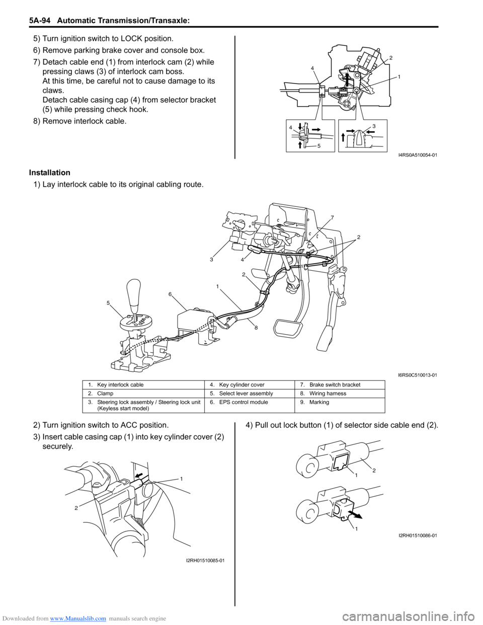
5) Turn ignition switch to LOCK position.
6) Remove parking brake cover and console box.
7) Detach cable end (1) from interlock cam (2) while
pressing claws (3) of interlock cam boss.
At this time, be careful no t to cause damage to its
claws.
Detach cable casing cap (4 ) from selector bracket
(5) while pressing check hook.
8) Remove interlock cable.
Installation 1) Lay interlock cable to its original cabling route.
2) Turn ignition switch to ACC position.
3) Insert cable casing cap (1) into key cylinder cover (2) securely. 4) Pull out lock button (1) of selector side cable end (2).
4
5 31
2
4
I4RS0A510054-01
1 2
3
4
5 6 7
8
2
I6RS0C510013-01
1. Key interlock cable 4. Key cylinder cover7. Brake switch bracket
2. Clamp 5. Select lever assembly 8. Wiring harness
3. Steering lock assembly / Steering lock unit (Keyless start model) 6. EPS control module
9. Marking
1
2
I2RH01510085-01
1
1
2
I2RH01510086-01
Page 739 of 1496
Downloaded from www.Manualslib.com manuals search engine Automatic Transmission/Transaxle: 5A-95
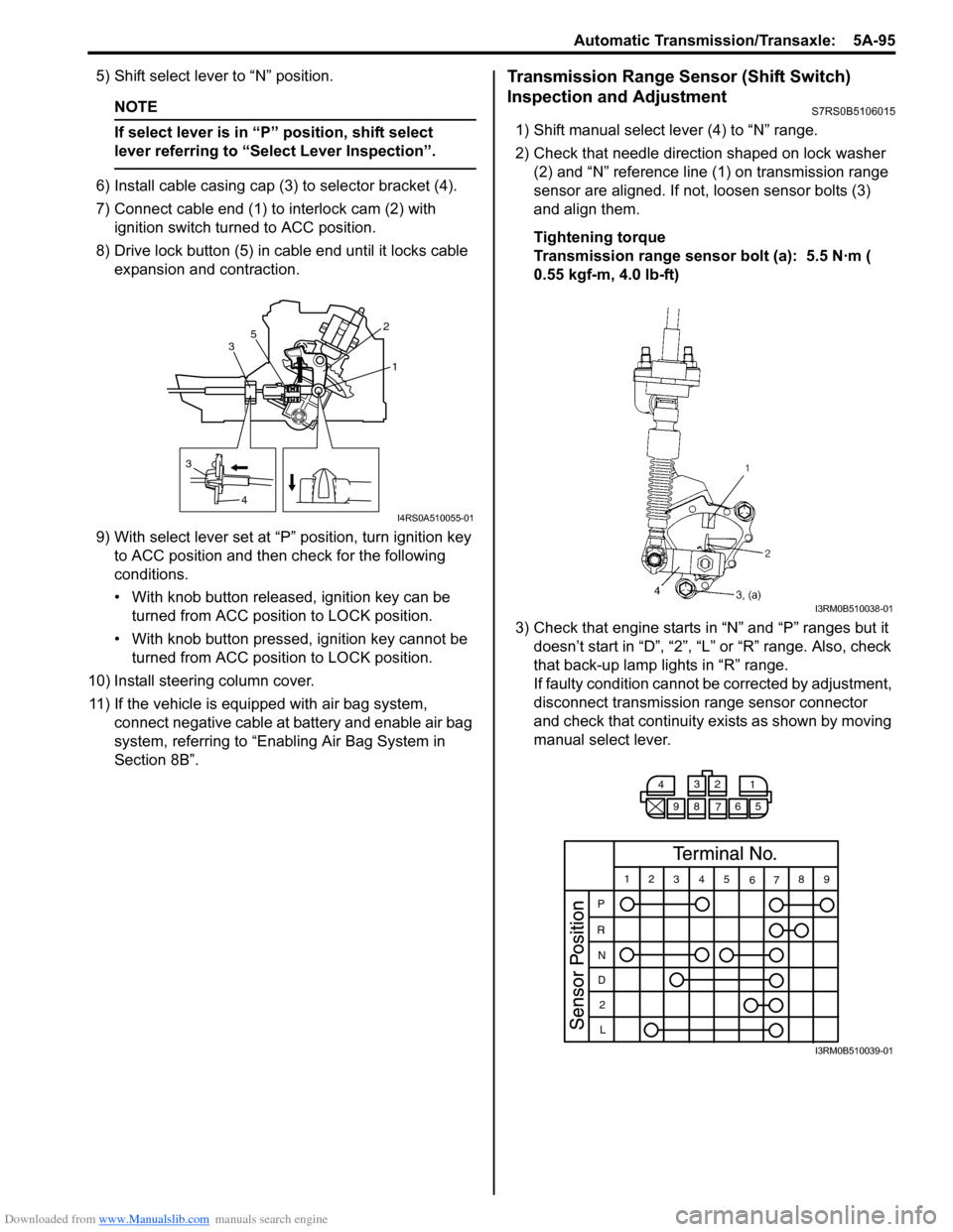
5) Shift select lever to “N” position.
NOTE
If select lever is in “P” position, shift select
lever referring to “Select Lever Inspection”.
6) Install cable casing cap (3) to selector bracket (4).
7) Connect cable end (1) to interlock cam (2) with ignition switch turned to ACC position.
8) Drive lock button (5) in cable end until it locks cable expansion and contraction.
9) With select lever set at “P ” position, turn ignition key
to ACC position and then check for the following
conditions.
• With knob button released, ignition key can be turned from ACC position to LOCK position.
• With knob button pressed, ignition key cannot be
turned from ACC position to LOCK position.
10) Install steering column cover. 11) If the vehicle is equipped with air bag system, connect negative cable at battery and enable air bag
system, referring to “Enabling Air Bag System in
Section 8B”.
Transmission Range Sensor (Shift Switch)
Inspection and Adjustment
S7RS0B5106015
1) Shift manual select lever (4) to “N” range.
2) Check that needle direction shaped on lock washer (2) and “N” reference line (1) on transmission range
sensor are aligned. If not, loosen sensor bolts (3)
and align them.
Tightening torque
Transmission range sensor bolt (a): 5.5 N·m (
0.55 kgf-m, 4.0 lb-ft)
3) Check that engine starts in “N” and “P” ranges but it doesn’t start in “D”, “2”, “L” or “R” range. Also, check
that back-up lamp lights in “R” range.
If faulty condition cannot be corrected by adjustment,
disconnect transmission range sensor connector
and check that continuity ex ists as shown by moving
manual select lever.
3
4 1
2
3 5
I4RS0A510055-01
I3RM0B510038-01
4
3
2
1
98 76 5
12 345
6789
P
R N
D 2
L
I3RM0B510039-01
Page 810 of 1496
Downloaded from www.Manualslib.com manuals search engine 5A-166 Automatic Transmission/Transaxle:
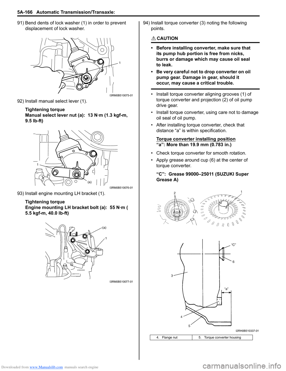
91) Bend dents of lock washer (1) in order to prevent displacement of lock washer.
92) Install manual select lever (1). Tightening torque
Manual select lever nut (a): 13 N·m (1.3 kgf-m,
9.5 lb-ft)
93) Install engine mounting LH bracket (1). Tightening torque
Engine mounting LH bracket bolt (a): 55 N·m (
5.5 kgf-m, 40.0 lb-ft) 94) Install torque converter (3) noting the following
points.
CAUTION!
• Before installing converter, make sure that its pump hub portion is free from nicks,
burrs or damage which may cause oil seal
to leak.
• Be very careful not to drop converter on oil pump gear. Damage in gear, should it
occur, may cause a critical trouble.
• Install torque converter aligning grooves (1) of torque converter and projection (2) of oil pump
drive gear.
• Install torque converter, using care not to damage oil seal of oil pump.
• After installing torque converter, check that distance “a” is within specification.
Torque converter installing position
“a”: More than 19.9 mm (0.783 in.)
• Check torque converter for smooth rotation.
• Apply grease around cup (6) at the center of torque converter.
“C”: Grease 99000–25011 (SUZUKI Super
Grease A)
1
I3RM0B510075-01
1
(a)
I3RM0B510076-01
I3RM0B510077-01
4. Flange nut 5. Torque converter housing
I2RH0B510337-01
Page 819 of 1496

Downloaded from www.Manualslib.com manuals search engine Manual Transmission/Transaxle: 5B-5
Gear Shift Control Lever and Cable ComponentsS7RS0B5206003
1
3
4
(a)
7
A
(b)5
A
111 2
10
(c)
9
6
8 2
I7RS0A521001-03
1. Gear shift control lever knob 9. Cable bracket
2. Cable bracket bolt 10. Clip
Be sure to direct claw of clip to M/T side as shown in figure.
3. Gear shift lever boot 11. To gear shift control lever assembly
4. Gear shift control cable : Apply grease 99000-25011 to cable end. 12. To M/T
5. Gear select control cable : Apply grease 99000-25011 to cable end. : 13 N
⋅m (1.3 kgf-m, 9.5 lb-ft)
6. Gear shift control lever assembly mounting nut : 10 N⋅m (1.0 kgf-m, 7.5 lb-ft)
7. Gear shift control lever assembly : 55 N⋅m (5.5 kgf-m, 40.0 lb-ft)
8. Cable grommet bolt : Do not reuse.
Page 866 of 1496
Downloaded from www.Manualslib.com manuals search engine 5C-14 Clutch:
Special Tools and Equipment
Recommended Service MaterialS7RS0B5308001
NOTE
Required service material is also described in the following.
“Clutch Fluid Pipe and Hose Components”
“Clutch Pedal and Clutch Pedal Bracket Components”
“Clutch Cover, Clutch Disc and Flywheel Components”
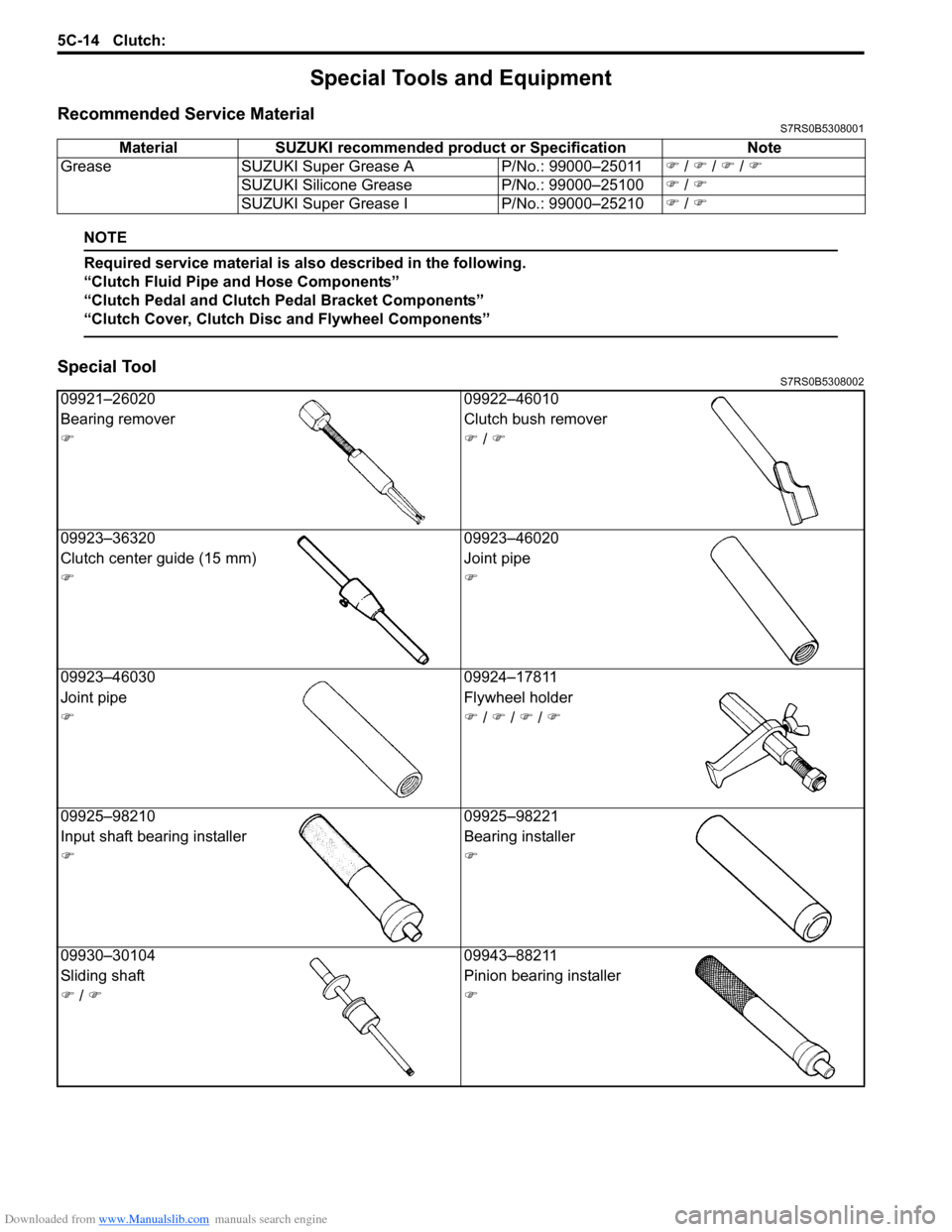
Special ToolS7RS0B5308002
Material SUZUKI recommended product or Specification Note
Grease SUZUKI Super Grease A P/No.: 99000–25011�) / �) / �) / �)
SUZUKI Silicone Grease P/No.: 99000–25100�) / �)
SUZUKI Super Grease I P/No.: 99000–25210�) / �)
09921–26020 09922–46010
Bearing remover Clutch bush remover
�)�) / �)
09923–36320 09923–46020
Clutch center guide (15 mm) Joint pipe
�)�)
09923–46030 09924–17811
Joint pipe Flywheel holder
�)�) / �) / �) / �)
09925–98210 09925–98221
Input shaft bearing inst aller Bearing installer
�)�)
09930–30104 09943–88211
Sliding shaft Pinion bearing installer
�) / �)�)