2005 SUZUKI SWIFT acc
[x] Cancel search: accPage 1296 of 1496
Downloaded from www.Manualslib.com manuals search engine 9C-1 Instrumentation / Driver Info. / Horn:
Body, Cab and Accessories
Instrumentation / Driver Info. / Horn
Precautions
Precautions in Diagnosing Troubles for Combination MeterS7RS0B9300001
Combination meter uses signals (information) from each control module by CAN communication to control
speedometer, tachometer, engine coolant temp meter, warning light and indicator light (other than air bag warning
light, high beam indicator light, EPS warn ing light and turn signal indicator light). Therefore, check that no DTC is
detected in each module before performing combination me ter symptom diagnosis. If any DTC is detected, correct
trouble indicated by that DTC troubleshooting first.
General Description
CAN Communication System DescriptionS7RS0B9301001
Refer to “CAN Communication System Description in Section 1A” for Can communication system description.
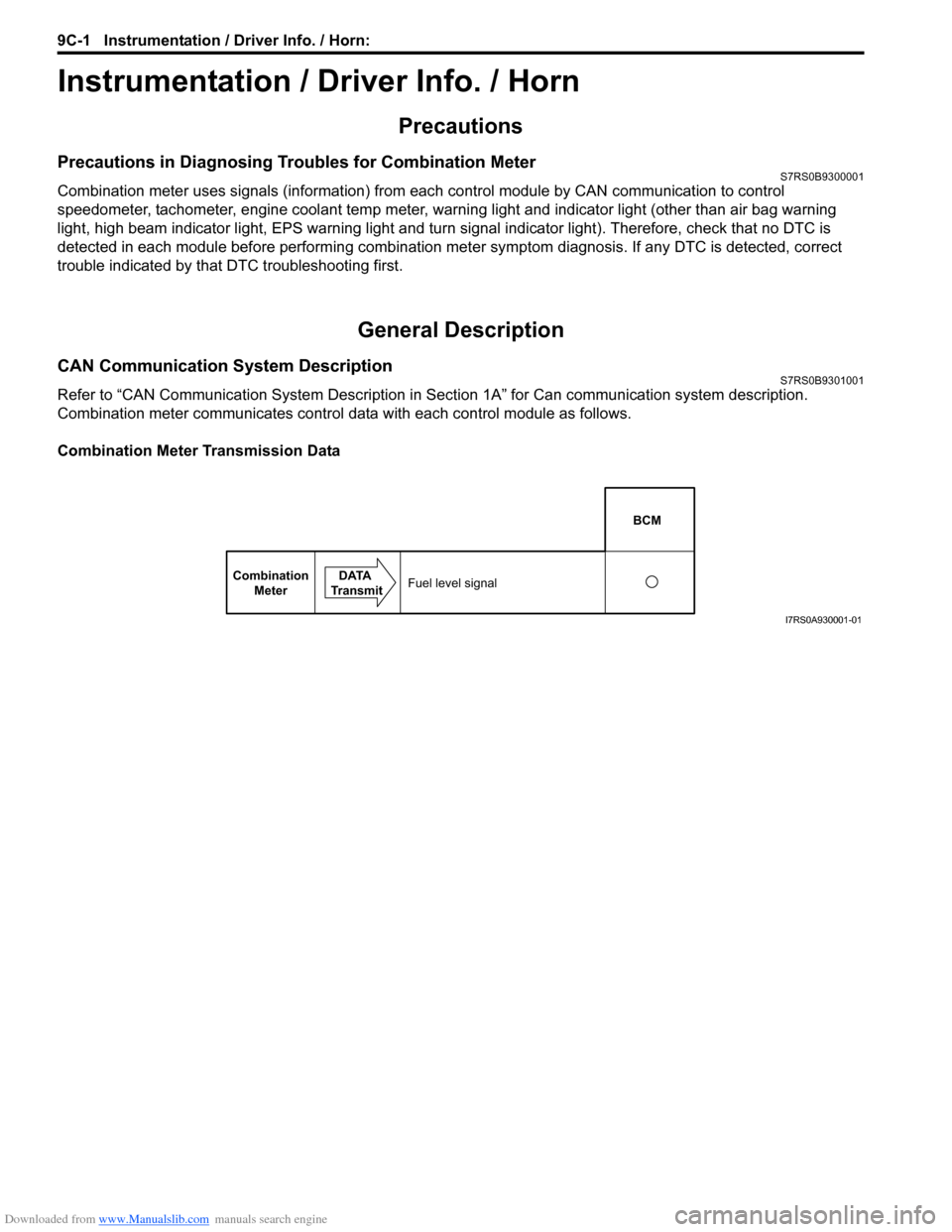
Combination meter communicates control data with each control module as follows.
Combination Meter Transmission Data
BCM
Combination Meter DATA
TransmitFuel level signal
I7RS0A930001-01
Page 1298 of 1496
Downloaded from www.Manualslib.com manuals search engine 9C-3 Instrumentation / Driver Info. / Horn:
Auto Volume Control System Description (If Equipped)S7RS0B9301002
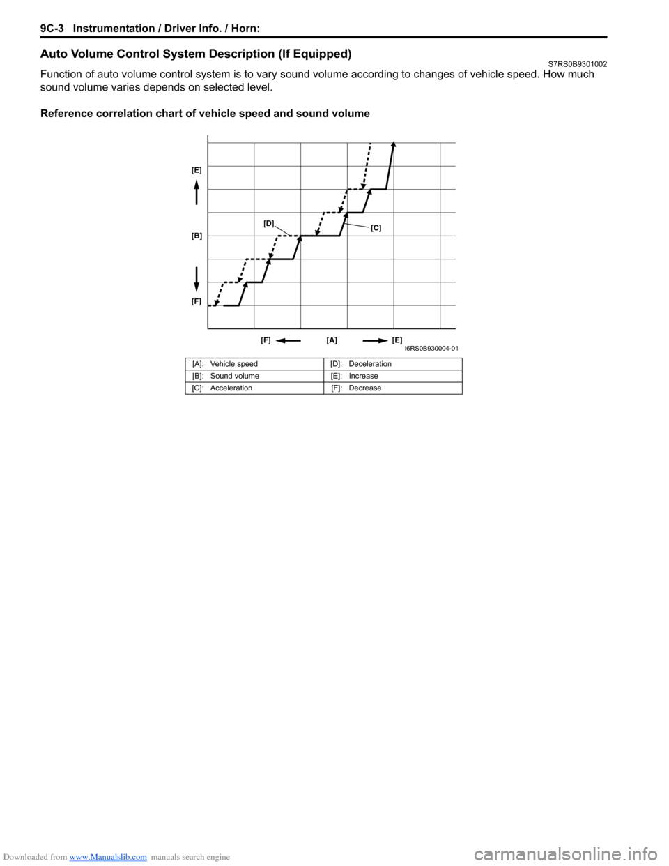
Function of auto volume control system is to vary sound volume according to changes of vehicle speed. How much
sound volume varies depends on selected level.
Reference correlation chart of vehicle speed and sound volume
[A]: Vehicle speed [D]: Deceleration
[B]: Sound volume [E]: Increase
[C]: Acceleration [F]: Decrease
[A][E]
[F]
[B] [E]
[F]
[C]
[D]
I6RS0B930004-01
Page 1308 of 1496
Downloaded from www.Manualslib.com manuals search engine 9C-13 Instrumentation / Driver Info. / Horn:
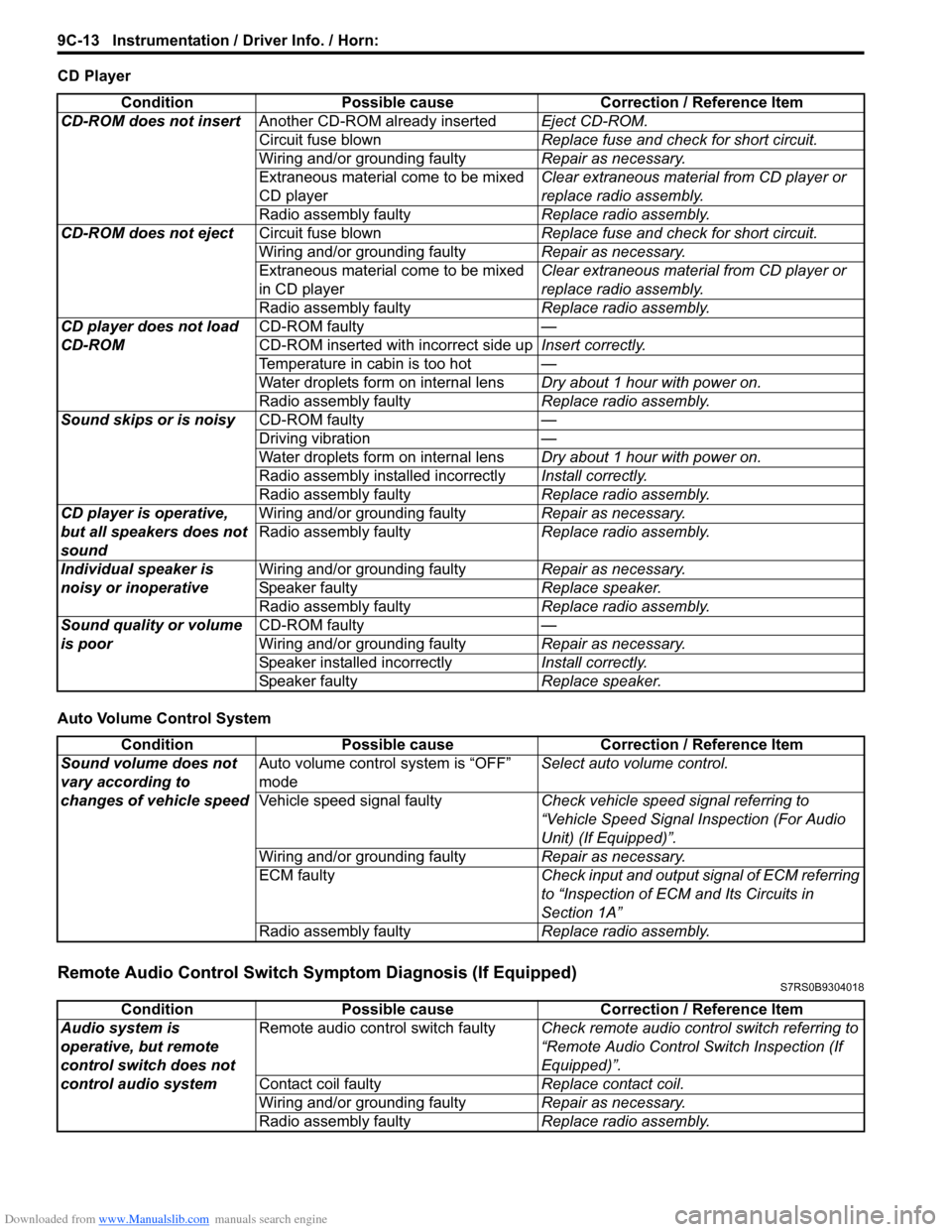
CD Player
Auto Volume Control System
Remote Audio Control Switch Symptom Diagnosis (If Equipped)S7RS0B9304018
ConditionPossible cause Correction / Reference Item
CD-ROM does not insert Another CD-ROM already inserted Eject CD-ROM.
Circuit fuse blown Replace fuse and check for short circuit.
Wiring and/or grounding faulty Repair as necessary.
Extraneous material come to be mixed
CD player Clear extraneous material from CD player or
replace radio assembly.
Radio assembly faulty Replace radio assembly.
CD-ROM does not eject Circuit fuse blown Replace fuse and check for short circuit.
Wiring and/or grounding faulty Repair as necessary.
Extraneous material come to be mixed
in CD player Clear extraneous material from CD player or
replace radio assembly.
Radio assembly faulty Replace radio assembly.
CD player does not load
CD-ROM CD-ROM faulty
—
CD-ROM inserted wit h incorrect side upInsert correctly.
Temperature in cabin is too hot —
Water droplets form on internal lens Dry about 1 hour with power on.
Radio assembly faulty Replace radio assembly.
Sound skips or is noisy CD-ROM faulty —
Driving vibration —
Water droplets form on internal lens Dry about 1 hour with power on.
Radio assembly installed incorrectly Install correctly.
Radio assembly faulty Replace radio assembly.
CD player is operative,
but all speakers does not
sound Wiring and/or grounding faulty
Repair as necessary.
Radio assembly faulty Replace radio assembly.
Individual speaker is
noisy or inoperative Wiring and/or grounding faulty
Repair as necessary.
Speaker faulty Replace speaker.
Radio assembly faulty Replace radio assembly.
Sound quality or volume
is poor CD-ROM faulty
—
Wiring and/or grounding faulty Repair as necessary.
Speaker installed incorrectly Install correctly.
Speaker faulty Replace speaker.
ConditionPossible cause Correction / Reference Item
Sound volume does not
vary according to
changes of vehicle speed Auto volume control system is “OFF”
mode
Select auto volume control.
Vehicle speed signal faulty Check vehicle speed signal referring to
“Vehicle Speed Signal Inspection (For Audio
Unit) (If Equipped)”.
Wiring and/or grounding faulty Repair as necessary.
ECM faulty Check input and output signal of ECM referring
to “Inspection of ECM and Its Circuits in
Section 1A”
Radio assembly faulty Replace radio assembly.
ConditionPossible cause Correction / Reference Item
Audio system is
operative, but remote
control switch does not
control audio system Remote audio control switch faulty
Check remote audio control switch referring to
“Remote Audio Control Switch Inspection (If
Equipped)”.
Contact coil faulty Replace contact coil.
Wiring and/or grounding faulty Repair as necessary.
Radio assembly faulty Replace radio assembly.
Page 1309 of 1496
Downloaded from www.Manualslib.com manuals search engine Instrumentation / Driver Info. / Horn: 9C-14
Navigation Symptom Diagnosis (If Equipped)S7RS0B9304019
Repair Instructions
Ignition Switch Removal and InstallationS7RS0B9306001
Removal
1) Disconnect negative (–) cable at battery.
2) Confirm that ignition key is removed.
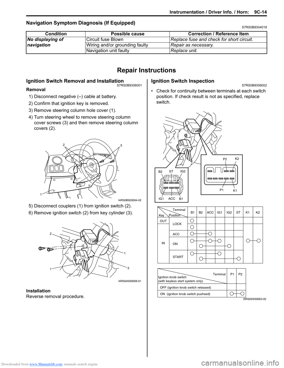
3) Remove steering column hole cover (1).
4) Turn steering wheel to remove steering column cover screws (3) and then remove steering column
covers (2).
5) Disconnect couplers (1) from ignition switch (2).
6) Remove ignition switch (2) from key cylinder (3).
Installation
Reverse removal procedure.
Ignition Switch InspectionS7RS0B9306002
• Check for continuity between terminals at each switch
position. If check result is not as specified, replace
switch.
Condition Possible cause Correction / Reference Item
No displaying of
navigation Circuit fuse Blown
Replace fuse and check for short circuit.
Wiring and/or grounding faulty Repair as necessary.
Navigation unit faulty Replace unit.
1
32
I4RS0B920004-02
1 1
2
3
I4RS0A930008-01
PositionTerminal
LOCK
ACC
ON
START
OUT
INK2K1ST
IG2
IG1
ACC
B1 B2
Ignition knob switch
(with keyless start system only)
ACC
IG1 IG2
ST
B2
B1 K2
K1
P2
P1
Terminal
OFF (ignition knob switch released) ON (ignition knob switch pushsed)P1 P2
Key
I5RS0D930003-02
Page 1318 of 1496
Downloaded from www.Manualslib.com manuals search engine 9D-1 Wipers / Washers:
Body, Cab and Accessories
Wipers / Washers
Diagnostic Information and Procedures
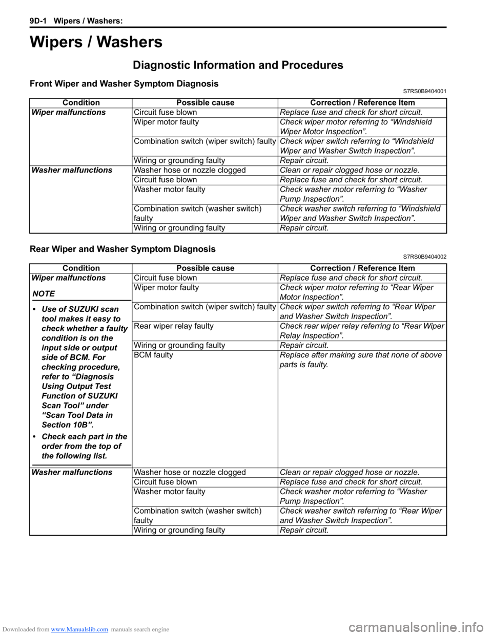
Front Wiper and Washer Symptom DiagnosisS7RS0B9404001
Rear Wiper and Washer Symptom DiagnosisS7RS0B9404002
ConditionPossible cause Correction / Reference Item
Wiper malfunctions Circuit fuse blown Replace fuse and check for short circuit.
Wiper motor faulty Check wiper motor referring to “Windshield
Wiper Motor Inspection”.
Combination switch (wiper switch) faulty Check wiper switch referring to “Windshield
Wiper and Washer Switch Inspection”.
Wiring or grounding faulty Repair circuit.
Washer malfunctions Washer hose or nozzle clogged Clean or repair clogged hose or nozzle.
Circuit fuse blown Replace fuse and check for short circuit.
Washer motor faulty Check washer motor referring to “Washer
Pump Inspection”.
Combination switch (washer switch)
faulty Check washer switch referring to “Windshield
Wiper and Washer Switch Inspection”.
Wiring or grounding faulty Repair circuit.
ConditionPossible cause Correction / Reference Item
Wiper malfunctions
NOTE
• Use of SUZUKI scan tool makes it easy to
check whether a faulty
condition is on the
input side or output
side of BCM. For
checking procedure,
refer to “Diagnosis
Using Output Test
Function of SUZUKI
Scan Tool” under
“Scan Tool Data in
Section 10B”.
• Check each part in the order from the top of
the following list.
Circuit fuse blown Replace fuse and check for short circuit.
Wiper motor faulty Check wiper motor referring to “Rear Wiper
Motor Inspection”.
Combination switch (wiper switch) faulty Check wiper switch referring to “Rear Wiper
and Washer Switch Inspection”.
Rear wiper relay faulty Check rear wiper relay referring to “Rear Wiper
Relay Inspection”.
Wiring or grounding faulty Repair circuit.
BCM faulty Replace after making sure that none of above
parts is faulty.
Washer malfunctions Washer hose or nozzle clogged Clean or repair clogged hose or nozzle.
Circuit fuse blown Replace fuse and check for short circuit.
Washer motor faulty Check washer motor referring to “Washer
Pump Inspection”.
Combination switch (washer switch)
faulty Check washer switch referring to “Rear Wiper
and Washer Switch Inspection”.
Wiring or grounding faulty Repair circuit.
Page 1328 of 1496
Downloaded from www.Manualslib.com manuals search engine 9E-1 Glass / Windows / Mirrors:
Body, Cab and Accessories
Glass / Windows / Mirrors
General Description
Rear End Door Window Defogger System DescriptionS7RS0B9501001
The rear end door window defogger is controlled by BCM. For the BCM description refer to “BCM General Description
in Section 10B”.
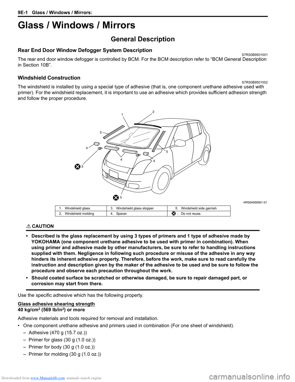
Windshield ConstructionS7RS0B9501002
The windshield is installed by using a special type of adhesive (that is, one component urethane adhesive used with
primer). For the windshield replacement, it is important to use an adhesive which provides sufficient adhesion strength
and follow the proper procedure.
CAUTION!
• Described is the glass replacement by using 3 types of primers and 1 type of adhesive made by YOKOHAMA (one component urethane adhesive to be used with primer in combination). When
using primer and adhesive made by other manufacturers, be sure to refer to handling instructions
supplied with them. Negligence in following such procedure or misuse of the adhesive in any way
hinders its inherent adhesive property. Therefore, before the work, make sure to read carefully the
instruction and description given by the maker of the adhesive to be used and be sure to follow the
procedure and observe each precaution throughout the work.
• Should coated surface be scratched or otherwise damaged, be sure to repair damaged part, or corrosion may start from there.
Use the specific adhesive which has the following property.
Glass adhesive shearing strength
40 kg/cm2 (569 lb/in2) or more
Adhesive materials and tools required for removal and installation.
• One component urethane adhesive and primers used in combination (For one sheet of windshield). – Adhesive (470 g (15.7 oz.))
– Primer for glass (30 g (1.0 oz.))
– Primer for body (30 g (1.0 oz.))
– Primer for molding (30 g (1.0 oz.))
3
3 1
2
44
4
5
5
I4RS0A950001-01
1. Windshield glass
3. Windshield glass stopper 5. Windshield side garnish
2. Windshield molding 4. Spacer : Do not reuse.
Page 1342 of 1496
Downloaded from www.Manualslib.com manuals search engine 9E-15 Glass / Windows / Mirrors:
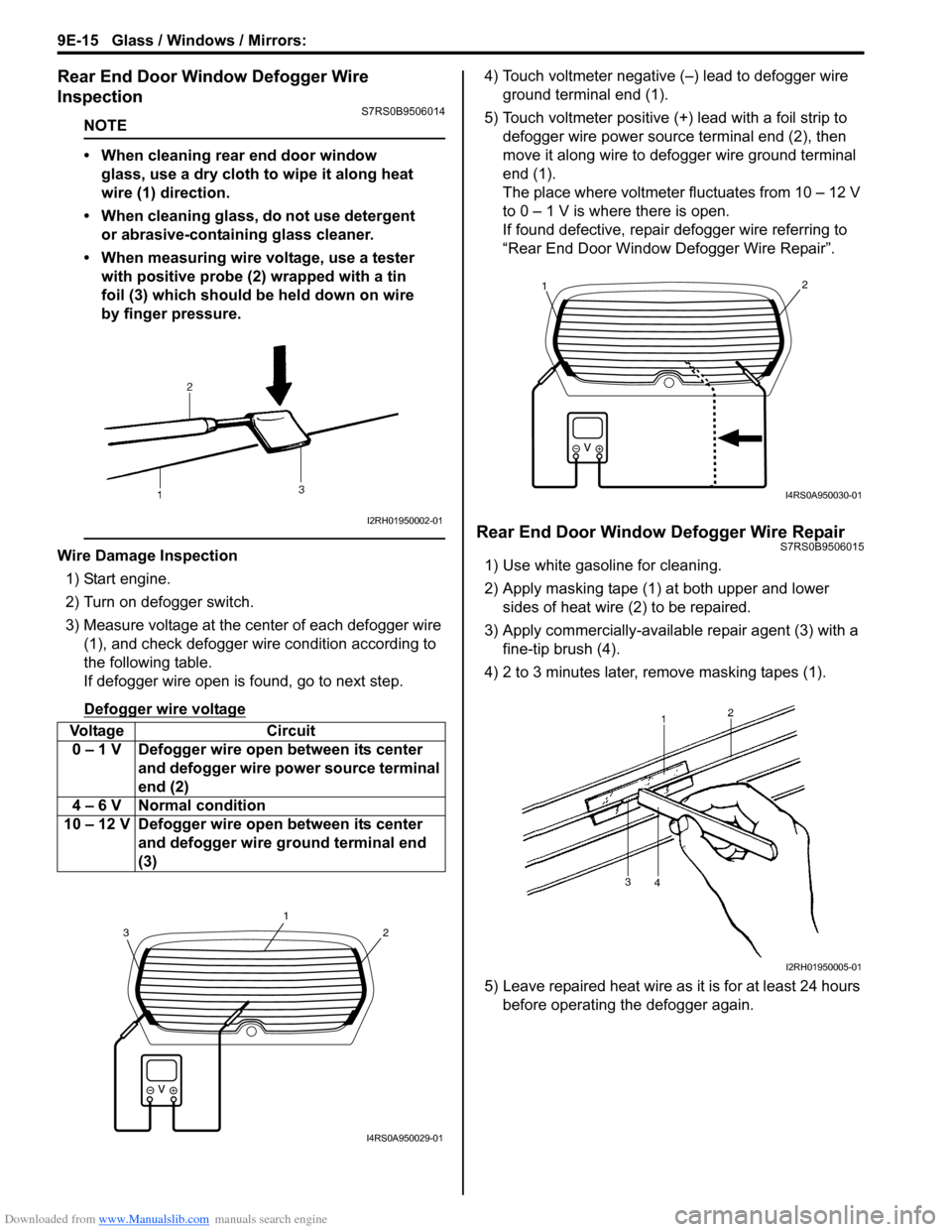
Rear End Door Window Defogger Wire
Inspection
S7RS0B9506014
NOTE
• When cleaning rear end door window glass, use a dry cloth to wipe it along heat
wire (1) direction.
• When cleaning glass, do not use detergent or abrasive-containing glass cleaner.
• When measuring wire voltage, use a tester with positive probe (2) wrapped with a tin
foil (3) which should be held down on wire
by finger pressure.
Wire Damage Inspection
1) Start engine.
2) Turn on defogger switch.
3) Measure voltage at the center of each defogger wire (1), and check defogger wire condition according to
the following table.
If defogger wire open is found, go to next step.
Defogger wire voltage
4) Touch voltmeter negative (–) lead to defogger wire ground terminal end (1).
5) Touch voltmeter positive (+) lead with a foil strip to defogger wire power source terminal end (2), then
move it along wire to defogger wire ground terminal
end (1).
The place where voltmeter fluctuates from 10 – 12 V
to 0 – 1 V is where there is open.
If found defective, repair defogger wire referring to
“Rear End Door Window Defogger Wire Repair”.
Rear End Door Window Defogger Wire RepairS7RS0B9506015
1) Use white gasoline for cleaning.
2) Apply masking tape (1) at both upper and lower sides of heat wire (2) to be repaired.
3) Apply commercially-available repair agent (3) with a fine-tip brush (4).
4) 2 to 3 minutes later, remove masking tapes (1).
5) Leave repaired heat wire as it is for at least 24 hours before operating the defogger again.
Voltage Circuit
0 – 1 V Defogger wire open between its center and defogger wire power source terminal
end (2)
4 – 6 V Normal condition
10 – 12 V Defogger wire open between its center and defogger wire ground terminal end
(3)
I2RH01950002-01
2
1
3
I4RS0A950029-01
21
I4RS0A950030-01
I2RH01950005-01
Page 1347 of 1496
Downloaded from www.Manualslib.com manuals search engine Security and Locks: 9F-1
Body, Cab and Accessories
Security and Locks
General Description
Key Coding ConstructionS7RS0B9601001
Key Usage and Identification
Key is used for ignition and door lock cylinders. Key is cut on both edges to make them reversible.
Key identification is obtained from five character key code stamped on key code tag. Using this key code, key code
cutting combination can be determined from a code list (ava ilable to owners of key cutting equipment from suppliers).
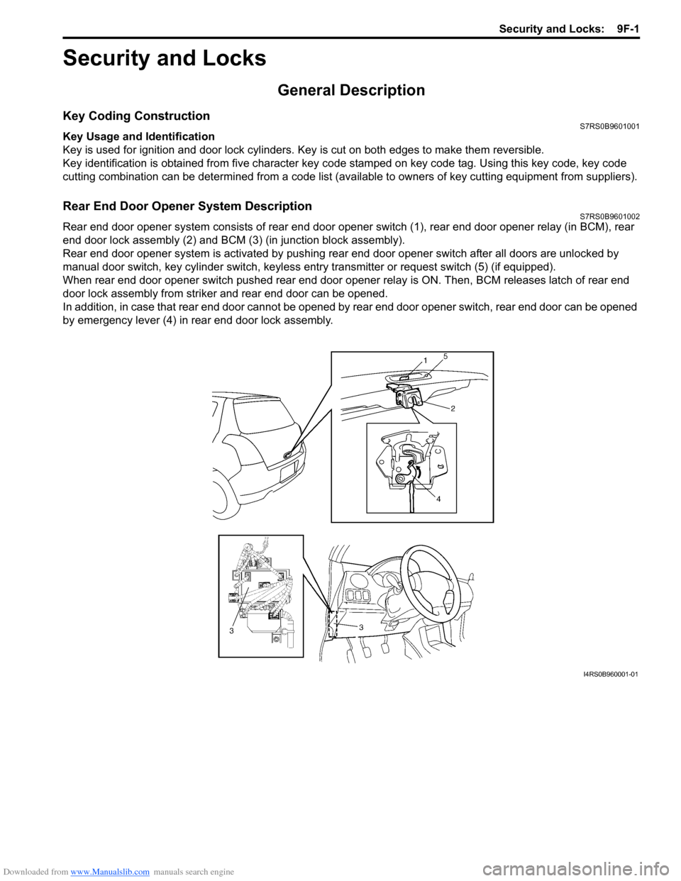
Rear End Door Opener System DescriptionS7RS0B9601002
Rear end door opener system consists of rear end door opener switch (1), rear end door opener relay (in BCM), rear
end door lock assembly (2) and BCM (3) (in junction block assembly).
Rear end door opener system is activated by pushing re ar end door opener switch after all doors are unlocked by
manual door switch, key cylinder s witch, keyless entry transmitter or request switch (5) (if equipped).
When rear end door opener switch pushed rear end door opener relay is ON. Then, BCM releases latch of rear end
door lock assembly from striker and rear end door can be opened.
In addition, in case that rear end door cannot be opened by rear end door opener switch, rear end door can be opened
by emergency lever (4) in rear end door lock assembly.
I4RS0B960001-01