2005 SUZUKI SWIFT motor
[x] Cancel search: motorPage 86 of 1496
Downloaded from www.Manualslib.com manuals search engine 1A-36 Engine General Information and Diagnosis:
O2S B1 S1 ACT (HEATED OXYGEN SENSOR-1,
ACTIVE / INACTIVE)
This parameter indicates activation condition of HO2S-1.
ACTIVE: Activating
INACTIVE: warming up or at stop
O2S SENSOR B1 S2 (HEATED OXYGEN SENSOR-2,
V)
It indicates output voltage of HO2S-2 installed on
exhaust pipe (post-catalyst). It is used to detect catalyst
deterioration.
O2S B1 S2 ACT (HEATED OXYGEN SENSOR-2,
ACTIVE / INACTIVE)
This parameter indicates acti vation condition of HO2S-2.
ACTIVE: Activating
INACTIVE: warming up or at stop
FUEL SYSTEM (FUEL SYSTEM STATUS)
Air/fuel ratio feedback loop status displayed as one of
the followings.
OPEN: Open-loop has not yet satisfied conditions to go
closed loop.
CLOSED: Closed-loop using oxygen sensor(s) as
feedback for fuel control.
OPEN-DRIVE COND: Open-loop due to driving
conditions (Power enrichment, etc.).
OPEN SYS FAULT: Open-loop due to detected system
fault.
MAP (MANIFOLD ABSOLUTE PRESSURE, in.Hg,
kPa)
This value indicates how much correction is necessary
to keep the air/fuel mixture stoichiometrical.
It is detected by manifold absolute pressure sensor.
BAROMETRIC PRESS (kPa, in.Hg)
This parameter represents a measurement of barometric
air pressure and is used for al titude correction of the fuel
injection quantity and IAC valve control.
STEP EGR FLOW DUTY (%)
This parameter indicates opening rate of EGR valve
which controls the amount of EGR flow.
FUEL CUT (ON/OFF)
ON: Fuel being cut (output signal to injector is stopped)
OFF: Fuel not being cut
A/C PRESSURE (A/C REFRIGERANT ABSOLUTE
PRESSURE, kPa)
This parameter indicates A/C refrigerant absolute
pressure calculated by ECM.
CLOSED THROTTLE PO S (CLOSED THROTTLE
POSITION, ON/OFF)
This parameter reads ON wh en throttle valve is fully
closed, or OFF when it is not fully closed. CANIST PRG DUTY (EVAP CANISTER PURGE FLOW
DUTY, %)
This parameter indicates valve ON (valve open) time
rate within a certain set cycle of EVAP canister purge
valve which controls the amount of EVAP purge.
IGNITION ADVANCE (IGNITION TIMING ADVANCE
FOR NO.1 CYLINDER,
°)
Ignition timing of No.1 cylinder is commanded by ECM.
The actual ignition timing should be checked by using
the timing light.
BATTERY VOLTAGE (V)
This parameter indicates battery positive voltage
inputted from main relay to ECM.
FUEL PUMP (ON/OFF)
ON is displayed when ECM activates the fuel pump via
the fuel pump relay switch.
ELECTRIC LOAD (ON/OFF)
ON: Headlight or small light ON signal inputted.
OFF: Above electric loads all turned OFF.
BRAKE SW (ON/OFF)
This parameter indicates the state of the brake switch.
RADIATOR COOLING FAN (RADIATOR COOLING
FAN CONTROL RELAY, ON/OFF)
ON: Command for radiator cooling fan control relay
operation being output.
OFF: Command for relay operation not being output.
BLOWER FAN (ON/OFF)
This parameter indicates the state of the blower fan
motor switch.
A/C SWITCH (ON/OFF)
ON: Command for A/C operatio n being output from ECM
to HVAC.
OFF: Command for A/C oper ation not being output.
A/C COMP RELAY (A/C COMPRESSOR RELAY, ON/
OFF)
This parameter indicates the state of the A/C switch.
VEHICLE SPEED (km/h, mph)
It is computed based on pulse signals from vehicle
speed sensor.
VVT GAP (TARGET-ACTUAL POSITION, °)
It is calculated using the formula: target valve timing
advance – actual valve timing advance.
TP SENSOR 1 VOLT (THROTTLE POSITION SENSOR
(MAIN) OUTPUT VOLTAGE, V)
The TP sensor (main) reading provides throttle valve
opening information in the form of voltage.
Page 159 of 1496
Downloaded from www.Manualslib.com manuals search engine Engine General Information and Diagnosis: 1A-109
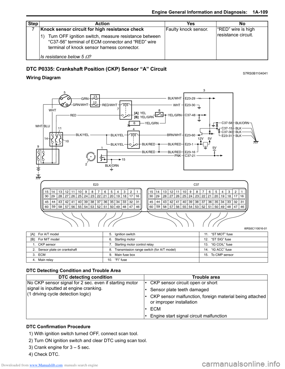
DTC P0335: Crankshaft Position (CKP) Sensor “A” CircuitS7RS0B1104041
Wiring Diagram
DTC Detecting Condition and Trouble Area
DTC Confirmation Procedure1) With ignition switch turned OFF, connect scan tool.
2) Turn ON ignition switch and clear DTC using scan tool.
3) Crank engine for 3 – 5 sec.
4) Check DTC. 7
Knock sensor circuit for high resistance check
1) Turn OFF ignition switch, measure resistance between
“C37-56” terminal of ECM connector and “RED” wire
terminal of knock sensor harness connector.
Is resistance below 5
Ω? Faulty knock sensor. “RED” wire is high
resistance circuit.
Step
Action YesNo
E23 C37
34
1819
567
1011
17
20
47 46
495051
2122
52 16
25 9
24
14
29
55
57 54 53
59
60 58 2
262728
15
30
56 4832 31
34353637
40
42 39 38
44
45 43 41 331
1213
238
34
1819
567
1011
17
20
47 46
495051
2122
52 16
25 9
24
14
29
55
57 54 53
59
60 58 2
262728
15
30
56 4832 31
34353637
40
42 39 38
44
45 43 41 331
1213
238
12V
5V
BLK/RED
BLK/RED
BLK/YELBLK/YEL
BLK/YEL
BRN/WHT
5
9 4
13
3
C37-30C37-15
C37-58
E23-31
BLK/ORN
BLKBLKBLK
10
BLK/RED
BLK/RED
E23-16
E23-60
E23-1
BLK/ORN
1
15
C37-21 5V
7RED/WHTGRN/WHT
GRN
RED
BLK/WHT
YEL/GRN
YEL/GRN
WHT
[A]: YEL
[B]: YEL/GRN
68
12
11
14
PNK
2
WHT
WHT/BLU
C37-48
E23-30
E23-29
I6RS0C110016-01
[A]: For A/T model 5. Ignition switch 11. “ST MOT” fuse
[B]: For M/T model 6. Starting motor 12. “ST SIG” fuse
1. CKP sensor 7. Starting motor control relay 13. “IG COIL” fuse
2. Sensor plate on crankshaft 8. Transmission range switch (for A/T model) 14. “IG ACC” fuse
3. ECM 9. Main fuse box 15. To CMP sensor
4. Main relay 10. “FI” fuse
DTC detecting condition Trouble area
No CKP sensor signal for 2 se c. even if starting motor
signal is inputted at engine cranking.
(1 driving cycle detection logic) • CKP sensor circuit open or short
• Sensor plate teeth damaged
• CKP sensor malfunction, foreign material being attached
or improper installation
•ECM
• Engine start signal circuit malfunction
Page 161 of 1496
Downloaded from www.Manualslib.com manuals search engine Engine General Information and Diagnosis: 1A-111
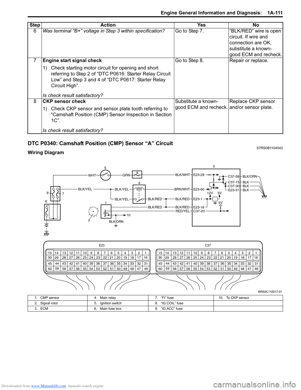
DTC P0340: Camshaft Position (CMP) Sensor “A” CircuitS7RS0B1104042
Wiring Diagram6
Was terminal “B+” voltage in Step 3 within specification? Go to Step 7. “BLK/RED” wire is open
circuit. If wire and
connection are OK,
substitute a known-
good ECM and recheck.
7 Engine start signal check
1) Check starting motor circuit for opening and short
referring to Step 2 of “DTC P0616: Starter Relay Circuit
Low” and Step 3 and 4 of “DTC P0617: Starter Relay
Circuit High”.
Is check result satisfactory? Go to Step 8. Repair or replace.
8 CKP sensor check
1) Check CKP sensor and sensor plate tooth referring to
“Camshaft Position (CMP) Sensor Inspection in Section
1C”.
Is check result satisfactory? Substitute a known-
good ECM and recheck.
Replace CKP sensor
and/or sensor plate.
Step Action Yes No
E23
C37
34
1819
567
1011
17
20
47 46
495051
2122
52 16
25 9
24
14
29
55
57 54 53
59
60 58 2
262728
15
30
56 4832 31
34353637
40
42 39 38
44
45 43 41 331
1213
238
34
1819
567
1011
17
20
47 46
495051
2122
52 16
25 9
24
14
29
55
57 54 53
59
60 58 2
262728
15
30
56 4832 31
34353637
40
42 39 38
44
45 43 41 331
1213
238
12V
5V
BLK/RED
BLK/RED
BLK/YELBLK/YEL
BLK/YEL
BRN/WHT
5
6 4
8
3
C37-30C37-15
C37-58
E23-31
BLK/ORN
BLKBLKBLK
BLK/RED
BLK/RED
E23-16
E23-60
E23-1
BLK/ORN
1
10
C37-20 5V
GRNBLK/WHT
9
7
RED/YEL
2
WHTE23-29
I6RS0C110017-01
1. CMP sensor 4. Main relay 7. “FI” fuse 10. To CKP sensor
2. Signal rotor 5. Ignition switch 8. “IG COIL” fuse
3. ECM 6. Main fuse box 9. “IG ACC” fuse
Page 169 of 1496
Downloaded from www.Manualslib.com manuals search engine Engine General Information and Diagnosis: 1A-119
DTC Troubleshooting
NOTE
• When measuring circuit voltage, resistance and/or pulse signal at ECM connector, connect the
special tool to ECM and/or the ECM connectors re ferring to “Inspection of ECM and Its Circuits”.
• Upon completion of inspection and repair work, perform “DTC Confirmation Procedure” and confirm that the trouble has been corrected.
Step Action YesNo
1 Was “Engine and Emission Control System Check”
performed? Go to Step 2.
Go to “Engine and
Emission Control
System Description”.
2 EGR valve power supply circuit check
1) Remove air intake pipe.
2) With ignition switch turned OFF, disconnect EGR valve
connector.
3) With ignition switch turned ON, measure voltage between “BLK/RED” wire terminal of EGR valve
connector and vehicle body ground.
Is check voltage 10 – 14 V? Go to Step 3.
“BLK/RED” wire is open
circuit.
3 Wire circuit check
1) Disconnect connectors from ECM with ignition switch
turned OFF.
2) Turn ON ignition switch.
3) Measure voltage between engine ground and each “GRN/RED”, “GRN/ORN”, “W HT/RED”, “BRN/YEL” wire
terminals of EGR valve connector.
Is each voltage 0 V? Go to Step 4.
Faulty wire(s) are
shorted to other circuit.
If wires are OK,
substitute a known-
good ECM and recheck.
4 Wire circuit check
1) With ignition switch turned OFF, measure resistance
between engine ground and each “GRN/RED”, “GRN/
ORN”, “WHT/RED”, “BRN/YEL” wire terminals of EGR
valve connector.
Is resistance infinity? Go to Step 5.
Faulty wire(s) are
shorted to ground
circuit.
If wires are OK,
substitute a known-
good ECM and recheck.
5 Short circuit check for EGR valve control circuit
1) With ignition turned OFF, measure resistance between
each EGR valve control circ uit wire (“GRN/RED”, “GRN/
ORN”, “WHT/RED” and “BRN/ YEL” wire) and each EGR
valve control circuit wire.
Is each resistance infinity? Go to Step 6.
Faulty wire(s) are short
circuit.
6 EGR valve stepper motor coil circuit check
1) With ignition switch turned OFF, connect EGR valve
connector.
2) Measure resistance between “E23-1/16” and each “C37- 4”, “C37-3”, “C37-19”, “C37-18” terminals of ECM
connector.
Is each resistance 20 – 31
Ω at 20 °C, 68 °F? Faulty ECM. Substitute
a known-good ECM and
recheck.
Go to Step 7.
7 EGR valve check
1) Check EGR valve resistance referring to “EGR Valve
Inspection in Section 1B”.
Is resistance within specified value? Faulty wire(s) are open
or high resistance
circuit. If wires are OK,
substitute a known-
good ECM and recheck.Faulty EGR valve.
Page 174 of 1496
Downloaded from www.Manualslib.com manuals search engine 1A-124 Engine General Information and Diagnosis:
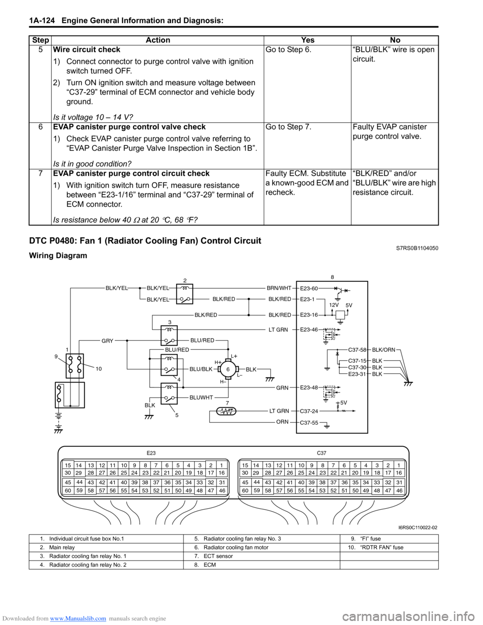
DTC P0480: Fan 1 (Radiator Cooling Fan) Control CircuitS7RS0B1104050
Wiring Diagram5
Wire circuit check
1) Connect connector to purge control valve with ignition
switch turned OFF.
2) Turn ON ignition switch and measure voltage between “C37-29” terminal of ECM connector and vehicle body
ground.
Is it voltage 10 – 14 V? Go to Step 6. “BLU/BLK” wire is open
circuit.
6 EVAP canister purge control valve check
1) Check EVAP canister purge control valve referring to
“EVAP Canister Purge Valve Inspection in Section 1B”.
Is it in good condition? Go to Step 7. Faulty EVAP canister
purge control valve.
7 EVAP canister purge control circuit check
1) With ignition switch turn OFF, measure resistance
between “E23-1/16” terminal and “C37-29” terminal of
ECM connector.
Is resistance below 40
Ω at 20 °C, 68 °F? Faulty ECM. Substitute
a known-good ECM and
recheck.
“BLK/RED” and/or
“BLU/BLK” wire are high
resistance circuit.
Step Action Yes No
E23
C37
34
1819
567
1011
17
20
47 46
495051
2122
52 16
25 9
24
14
29
55
57 54 53
59
60 58 2
262728
15
30
56 4832 31
34353637
40
42 39 38
44
45 43 41 331
1213
238
34
1819
567
1011
17
20
47 46
495051
2122
52 16
25 9
24
14
29
55
57 54 53
59
60 58 2
262728
15
30
56 4832 31
34353637
40
42 39 38
44
45 43 41 331
1213
238
BLK/REDBLK/RED
BLK/YELBLK/YEL
BLK/YEL
BRN/WHT
12V
5V5V
2
8
E23-1
E23-60
C37-58
C37-15 C37-30
BLK/ORN
BLKBLKE23-31BLK
BLK/RED
LT GRN
BLK/REDE23-16
E23-46
L+
L–
H–
H
+
BLU/RED
BLK
BLUWHTBLK
BLU/BLK
BLU/RED
4
GRN
GRY
E23-48
LT GRN
ORN
C37-24
C37-55
35
6
7
10
9
1
I6RS0C110022-02
1. Individual circuit fuse box No.1
5. Radiator cooling fan relay No. 3 9. “FI” fuse
2. Main relay 6. Radiator cooling fan motor10. “RDTR FAN” fuse
3. Radiator cooling fan relay No. 1 7. ECT sensor
4. Radiator cooling fan relay No. 2 8. ECM
Page 185 of 1496
Downloaded from www.Manualslib.com manuals search engine Engine General Information and Diagnosis: 1A-135
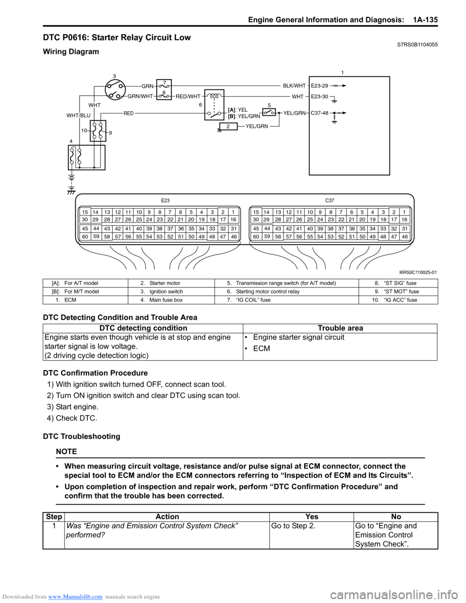
DTC P0616: Starter Relay Circuit LowS7RS0B1104055
Wiring Diagram
DTC Detecting Condition and Trouble Area
DTC Confirmation Procedure1) With ignition switch turned OFF, connect scan tool.
2) Turn ON ignition switch and clear DTC using scan tool.
3) Start engine.
4) Check DTC.
DTC Troubleshooting
NOTE
• When measuring circuit voltage, resistance and/ or pulse signal at ECM connector, connect the
special tool to ECM and/or the ECM connectors re ferring to “Inspection of ECM and Its Circuits”.
• Upon completion of inspection and repair work, perform “DTC Confirmation Procedure” and confirm that the trouble has been corrected.
E23 C37
34
1819
567
1011
17
20
47 46
495051
2122
52 16
25 9
24
14
29
55
57 54 53
59
60 58 2
262728
15
30
56 4832 31
34353637
40
42 39 38
44
45 43 41 331
1213
238
34
1819
567
1011
17
20
47 46
495051
2122
52 16
25 9
24
14
29
55
57 54 53
59
60 58 2
262728
15
30
56 4832 31
34353637
40
42 39 38
44
45 43 41 331
1213
238
3
4 7
1
6
RED/WHTGRN/WHT
GRN
RED
BLK/WHT
YEL/GRN
YEL/GRN
WHT
[A]: YEL
[B]: YEL/GRN
25
8
9
10
WHT
WHT/BLUC37-48
E23-30
E23-29
I6RS0C110025-01
[A]: For A/T model
2. Starter motor5. Transmission range switch (for A/T model) 8. “ST SIG” fuse
[B]: For M/T model 3. Ignition switch6. Starting motor control relay 9. “ST MOT” fuse
1. ECM 4. Main fuse box 7. “IG COIL” fuse 10. “IG ACC” fuse
DTC detecting condition Trouble area
Engine starts even though vehicle is at stop and engine
starter signal is low voltage.
(2 driving cycle detection logic) • Engine starter signal circuit
•ECM
Step
Action YesNo
1 Was “Engine and Emission Control System Check”
performed? Go to Step 2.
Go to “Engine and
Emission Control
System Check”.
Page 187 of 1496
Downloaded from www.Manualslib.com manuals search engine Engine General Information and Diagnosis: 1A-137
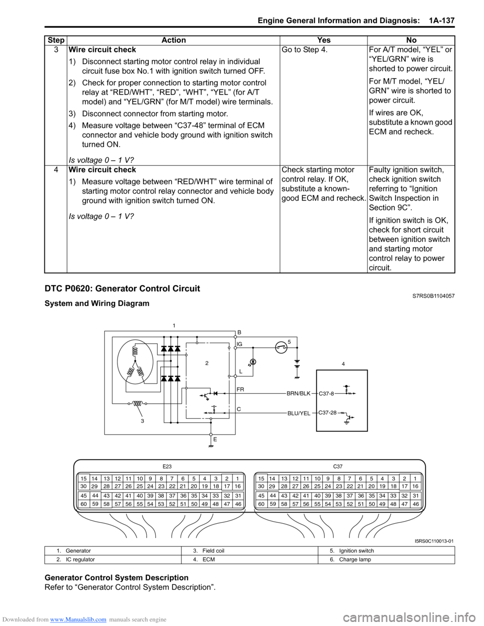
DTC P0620: Generator Control CircuitS7RS0B1104057
System and Wiring Diagram
Generator Control System Description
Refer to “Generator Control System Description”.3
Wire circuit check
1) Disconnect starting motor control relay in individual
circuit fuse box No.1 with ignition switch turned OFF.
2) Check for proper connection to starting motor control relay at “RED/WHT”, “RED”, “WHT”, “YEL” (for A/T
model) and “YEL/GRN” (for M/T model) wire terminals.
3) Disconnect connector from starting motor.
4) Measure voltage between “C37-48” terminal of ECM connector and vehicle body ground with ignition switch
turned ON.
Is voltage 0 – 1 V? Go to Step 4. For A/T model, “YEL” or
“YEL/GRN” wire is
shorted to power circuit.
For M/T model, “YEL/
GRN” wire is shorted to
power circuit.
If wires are OK,
substitute a known good
ECM and recheck.
4 Wire circuit check
1) Measure voltage between “RED/WHT” wire terminal of
starting motor control relay connector and vehicle body
ground with ignition switch turned ON.
Is voltage 0 – 1 V? Check starting motor
control relay. If OK,
substitute a known-
good ECM and recheck.
Faulty ignition switch,
check ignition switch
referring to “Ignition
Switch Inspection in
Section 9C”.
If ignition switch is OK,
check for short circuit
between ignition switch
and starting motor
control relay to power
circuit.
Step Action Yes No
IG
L
C
FR
E 4
2
BRN/BLKC37-8
BLU/YELC37-28
B
E23
C37
34
1819
567
1011
17
20
47 46
495051
2122
52 16
25 9
24
14
29
55
57 54 53
59
60 58 2
262728
15
30
56 4832 31
34353637
40
42 39 38
44
45 43 41 331
1213
238
34
1819
567
1011
17
20
47 46
495051
2122
52 16
25 9
24
14
29
55
57 54 53
59
60 58 2
262728
15
30
56 4832 31
34353637
40
42 39 38
44
45 43 41 331
1213
238 1
3 5
I5RS0C110013-01
1. Generator
3. Field coil 5. Ignition switch
2. IC regulator 4. ECM 6. Charge lamp
Page 188 of 1496
Downloaded from www.Manualslib.com manuals search engine 1A-138 Engine General Information and Diagnosis:
DTC Detecting Condition and Trouble Area
DTC Confirmation Procedure1) With ignition switch turned OFF, connect scan tool to DLC
2) Turn ON ignition switch and clear DTC.
3) Make sure that all accessory switches are tuned OFF.
4) Start engine and warm it up to normal operating temperature (ECT approx. 90 – 95 °C, 193 – 203 °F).
5) Turn ON the followi ng accessory switches.
• Head light switch.
• Blower motor switch (max position).
• Rear defogger switch.
6) Increase engine speed to 4000 rpm and keep it for 10 sec or more.
7) Decrease engine speed to idle.
8) Check DTC.
DTC Troubleshooting
NOTE
• When measuring circuit voltage, resistance and/ or pulse signal at ECM connector, connect the
special tool to ECM and/or the ECM connectors re ferring to “Inspection of ECM and Its Circuits”.
• Upon completion of inspection and repair work, perform “DTC Confirmation Procedure” and confirm that the trouble has been corrected.
DTC detecting condition Trouble area
• Battery voltage is higher than specification even through generator control is maximum regulation (duty 100%).
• Battery voltage is lower than specification even through generator control is minimum regulation (duty 0%) and electric
load is less than 15 A.
(1 driving cycle detection logic but MIL does not light up) • Generator and/or its circuit
• Electric load current sensor
•ECM
• Generator drive belt
Step
Action YesNo
1 Was “Engine and Emission Control System Check”
performed? Go to Step 2.
Go to “Engine and
Emission Control
System Check”.
2 Generator drive belt check
1) Check generator drive belt tension referring to “Water
Pump / Generator Drive Belt Tension Inspection and
Adjustment in Section 1J”.
Is check result satisfactory? Go to Step 3.
Adjust or replace
generator drive belt.