2005 SUZUKI SWIFT drive shaft
[x] Cancel search: drive shaftPage 85 of 1496
Downloaded from www.Manualslib.com manuals search engine Engine General Information and Diagnosis: 1A-35
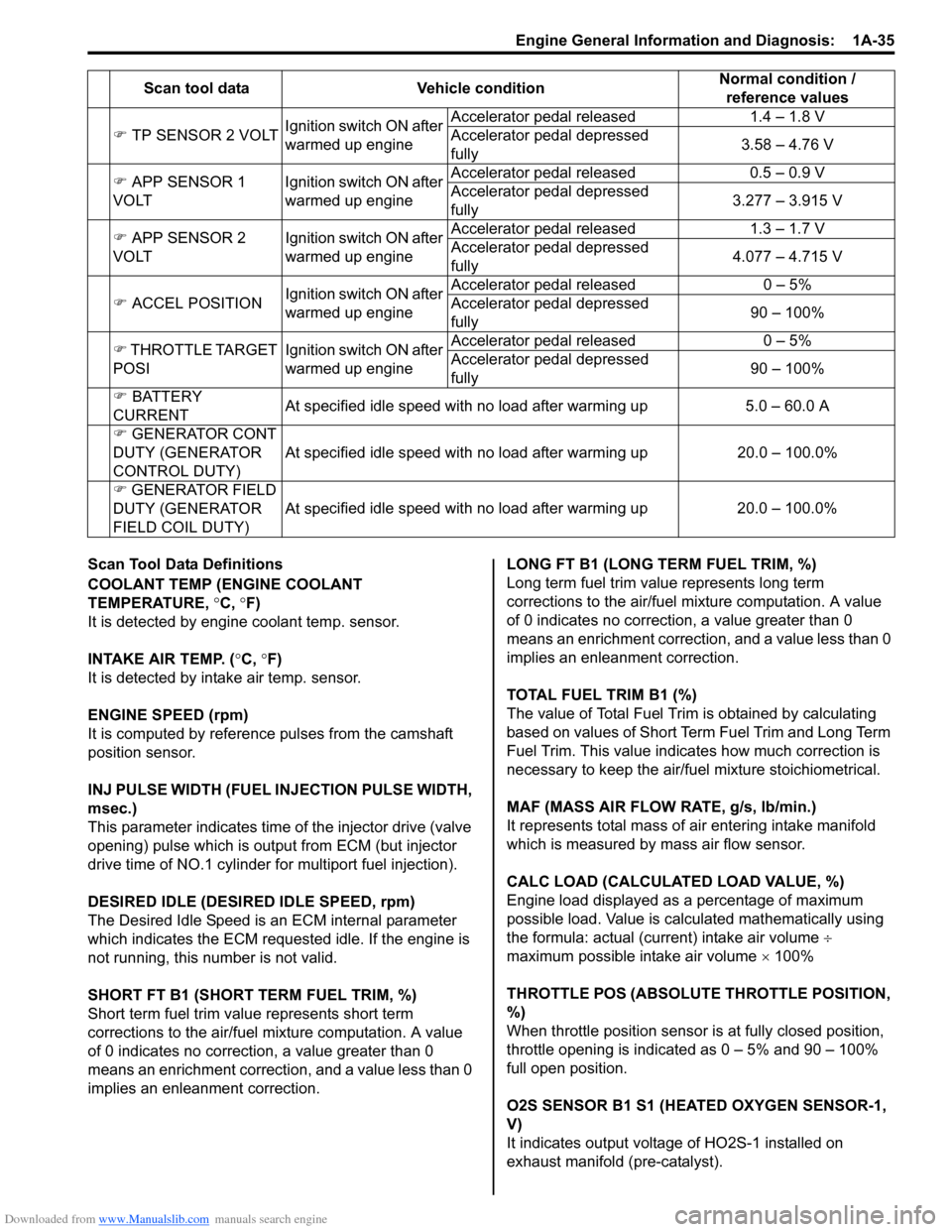
Scan Tool Data Definitions
COOLANT TEMP (ENGINE COOLANT
TEMPERATURE, °C, °F)
It is detected by engine coolant temp. sensor.
INTAKE AIR TEMP. ( °C, °F)
It is detected by intake air temp. sensor.
ENGINE SPEED (rpm)
It is computed by reference pulses from the camshaft
position sensor.
INJ PULSE WIDTH (FUEL INJECTION PULSE WIDTH,
msec.)
This parameter indicates time of the injector drive (valve
opening) pulse which is output from ECM (but injector
drive time of NO.1 cylinder fo r multiport fuel injection).
DESIRED IDLE (DESIRED IDLE SPEED, rpm)
The Desired Idle Speed is an ECM internal parameter
which indicates the ECM requested idle. If the engine is
not running, this number is not valid.
SHORT FT B1 (SHORT TERM FUEL TRIM, %)
Short term fuel trim valu e represents short term
corrections to the air/fuel mixture computation. A value
of 0 indicates no correction, a value greater than 0
means an enrichment correction, and a value less than 0
implies an enleanment correction. LONG FT B1 (LONG TERM FUEL TRIM, %)
Long term fuel trim value represents long term
corrections to the air/fuel mixture computation. A value
of 0 indicates no correction, a value greater than 0
means an enrichment correction, and a value less than 0
implies an enleanment correction.
TOTAL FUEL TRIM B1 (%)
The value of Total Fuel Trim is obtained by calculating
based on values of Short Term Fuel Trim and Long Term
Fuel Trim. This value indica
tes how much correction is
necessary to keep the air/fuel mixture stoichiometrical.
MAF (MASS AIR FLOW RATE, g/s, lb/min.)
It represents total mass of air entering intake manifold
which is measured by mass air flow sensor.
CALC LOAD (CALCULATED LOAD VALUE, %)
Engine load displayed as a percentage of maximum
possible load. Value is calculated mathematically using
the formula: actual (current) intake air volume ÷
maximum possible intake air volume × 100%
THROTTLE POS (ABSOLUTE THROTTLE POSITION,
%)
When throttle position sensor is at fully closed position,
throttle opening is indicated as 0 – 5% and 90 – 100%
full open position.
O2S SENSOR B1 S1 (HEA TED OXYGEN SENSOR-1,
V)
It indicates output voltage of HO2S-1 installed on
exhaust manifold (pre-catalyst).
�)
TP SENSOR 2 VOLT Ignition switch ON after
warmed up engine Accelerator pedal released
1.4 – 1.8 V
Accelerator pedal depressed
fully 3.58 – 4.76 V
�) APP SENSOR 1
VOLT Ignition switch ON after
warmed up engineAccelerator pedal released
0.5 – 0.9 V
Accelerator pedal depressed
fully 3.277 – 3.915 V
�) APP SENSOR 2
VOLT Ignition switch ON after
warmed up engineAccelerator pedal released
1.3 – 1.7 V
Accelerator pedal depressed
fully 4.077 – 4.715 V
�) ACCEL POSITION Ignition switch ON after
warmed up engine Accelerator pedal released
0 – 5%
Accelerator pedal depressed
fully 90 – 100%
�) THROTTLE TARGET
POSI Ignition switch ON after
warmed up engineAccelerator pedal released
0 – 5%
Accelerator pedal depressed
fully 90 – 100%
�) BATTERY
CURRENT At specified idle speed with no load after warming up
5.0 – 60.0 A
�) GENERATOR CONT
DUTY (GENERATOR
CONTROL DUTY) At specified idle speed with no load after warming up
20.0 – 100.0%
�) GENERATOR FIELD
DUTY (GENERATOR
FIELD COIL DUTY) At spe
cified idle speed with no load after warming up
20.0 – 100.0%
Scan tool data
Vehicle condition Normal condition /
reference values
Page 102 of 1496
Downloaded from www.Manualslib.com manuals search engine 1A-52 Engine General Information and Diagnosis:
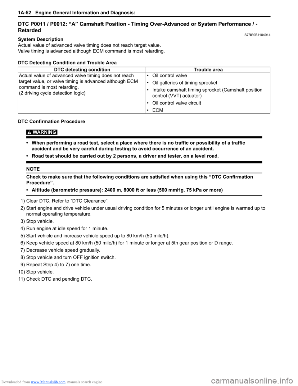
DTC P0011 / P0012: “A” Camshaft Position - Timing Over-Advanced or System Performance / -
Retarded
S7RS0B1104014
System Description
Actual value of advanced valve timing does not reach target value.
Valve timing is advanced although ECM command is most retarding.
DTC Detecting Condition and Trouble Area
DTC Confirmation Procedure
WARNING!
• When performing a road test, select a place where there is no traffic or possibility of a traffic accident and be very careful during testing to avoid occurrence of an accident.
• Road test should be carried out by 2 persons, a driver and tester, on a level road.
NOTE
Check to make sure that the following conditions are satisfied when using this “DTC Confirmation
Procedure”.
• Altitude (barometric pressure): 2400 m, 8000 ft or less (560 mmHg, 75 kPa or more)
1) Clear DTC. Refer to “DTC Clearance”.
2) Start engine and drive vehicle under usual driving condition for 5 minutes or longer until engine is warmed up to normal operating temperature.
3) Stop vehicle.
4) Run engine at idle speed for 1 minute.
5) Start vehicle and increase vehicle speed up to 80 km/h (50 mile/h).
6) Keep vehicle speed at 80 km/h (50 mile/h) for 1 minute or longer at 5th gear position or D range.
7) Decrease vehicle speed gradually.
8) Stop vehicle and turn OFF ignition switch.
9) Repeat Step 4) to 7) one time.
10) Stop vehicle. 11) Check DTC and pending DTC. DTC detecting condition
Trouble area
Actual value of advanced valve timing does not reach
target value, or valve timi ng is advanced although ECM
command is most retarding.
(2 driving cycle detection logic) • Oil control valve
• Oil galleries of timing sprocket
• Intake camshaft timing sprocket (Camshaft position
control (VVT) actuator)
• Oil control valve circuit
•ECM
Page 103 of 1496
Downloaded from www.Manualslib.com manuals search engine Engine General Information and Diagnosis: 1A-53
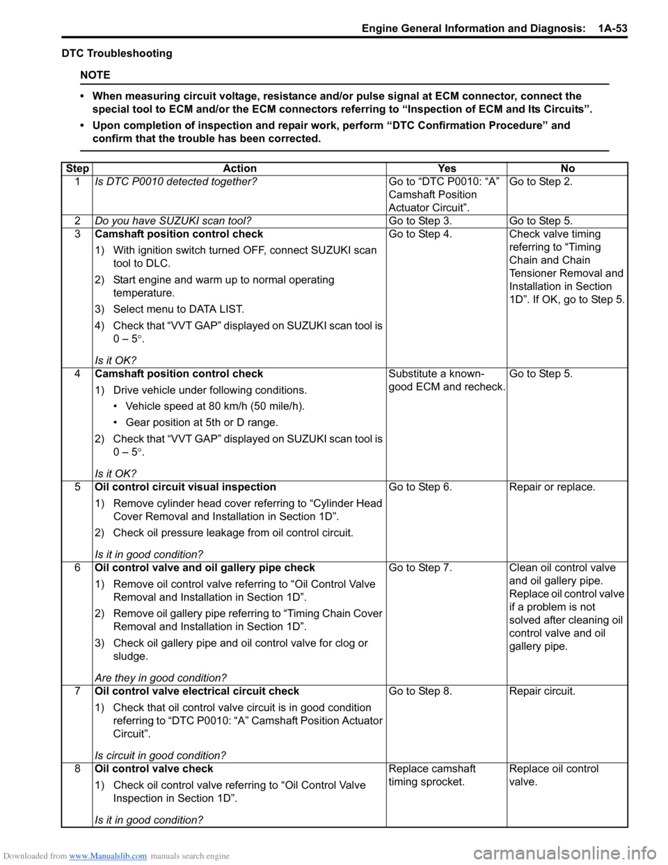
DTC Troubleshooting
NOTE
• When measuring circuit voltage, resistance and/or pulse signal at ECM connector, connect the
special tool to ECM and/or the ECM connectors re ferring to “Inspection of ECM and Its Circuits”.
• Upon completion of inspection and repair work, perform “DTC Confirmation Procedure” and confirm that the trouble has been corrected.
Step Action YesNo
1 Is DTC P0010 detected together? Go to “DTC P0010: “A”
Camshaft Position
Actuator Circuit”.Go to Step 2.
2 Do you have SUZUKI scan tool? Go to Step 3.Go to Step 5.
3 Camshaft position control check
1) With ignition switch turned OFF, connect SUZUKI scan
tool to DLC.
2) Start engine and warm up to normal operating temperature.
3) Select menu to DATA LIST.
4) Check that “VVT GAP” displayed on SUZUKI scan tool is 0 – 5 °.
Is it OK? Go to Step 4.
Check valve timing
referring to “Timing
Chain and Chain
Tensioner Removal and
Installation in Section
1D”. If OK, go to Step 5.
4 Camshaft position control check
1) Drive vehicle under following conditions.
• Vehicle speed at 80 km/h (50 mile/h).
• Gear position at 5th or D range.
2) Check that “VVT GAP” displayed on SUZUKI scan tool is 0 – 5 °.
Is it OK? Substitute a known-
good ECM and recheck.
Go to Step 5.
5 Oil control circuit visual inspection
1) Remove cylinder head cover referring to “Cylinder Head
Cover Removal and Insta llation in Section 1D”.
2) Check oil pressure leakage from oil control circuit.
Is it in good condition? Go to Step 6.
Repair or replace.
6 Oil control valve and oil gallery pipe check
1) Remove oil control valve re ferring to “Oil Control Valve
Removal and Installation in Section 1D”.
2) Remove oil gallery pipe refe rring to “Timing Chain Cover
Removal and Installation in Section 1D”.
3) Check oil gallery pipe and o il control valve for clog or
sludge.
Are they in good condition? Go to Step 7.
Clean oil control valve
and oil gallery pipe.
Replace oil control valve
if a problem is not
solved after cleaning oil
control valve and oil
gallery pipe.
7 Oil control valve electrical circuit check
1) Check that oil control valve circuit is in good condition
referring to “DTC P0010: “A” Camshaft Position Actuator
Circuit”.
Is circuit in good condition? Go to Step 8.
Repair circuit.
8 Oil control valve check
1) Check oil control valve refe rring to “Oil Control Valve
Inspection in Section 1D”.
Is it in good condition? Replace camshaft
timing sprocket.
Replace oil control
valve.
Page 155 of 1496
Downloaded from www.Manualslib.com manuals search engine Engine General Information and Diagnosis: 1A-105
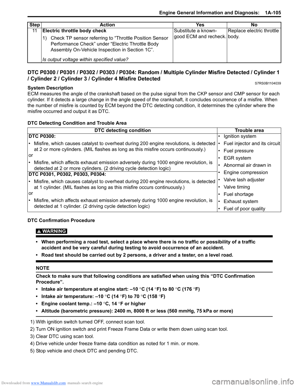
DTC P0300 / P0301 / P0302 / P0303 / P0304: Random / Multiple Cylinder Misfire Detected / Cylinder 1
/ Cylinder 2 / Cylinder 3 / Cylinder 4 Misfire Detected
S7RS0B1104039
System Description
ECM measures the angle of the crankshaft based on the pulse signal from the CKP sensor and CMP sensor for each
cylinder. If it detects a large change in the angle speed of the crankshaft, it concludes occurrence of a misfire. When
the number of misfire is counted by ECM beyond the DTC de tecting condition, it determines the cylinder where the
misfire occurred and output it as DTC.
DTC Detecting Condition and Trouble Area
DTC Confirmation Procedure
WARNING!
• When performing a road test, select a place where there is no traffic or possibility of a traffic accident and be very careful during testing to avoid occurrence of an accident.
• Road test should be carried out by 2 persons, a driver and a tester, on a level road.
NOTE
Check to make sure that following conditions ar e satisfied when using this “DTC Confirmation
Procedure”.
• Intake air temperature at engine start: –10 °C (14 ° F) to 80 °C (176 °F)
• Intake air temperature: –10 °C (14 °F) to 70 °C (158 °F)
• Engine coolant temp.: –10 °C, 14 °F or higher
• Altitude (barometric pressure): 2400 m, 8000 ft or less (560 mmHg, 75 kPa or more)
1) With ignition switch turned OFF, connect scan tool.
2) Turn ON ignition switch and print Freeze Frame Data or write them down using scan tool.
3) Clear DTC using scan tool.
4) Drive vehicle under freeze frame data condition as noted for 1 min. or more.
5) Stop vehicle and check DTC and pending DTC. 11
Electric throttle body check
1) Check TP sensor referring to “Throttle Position Sensor
Performance Check” under “Electric Throttle Body
Assembly On-Vehicle Inspection in Section 1C”.
Is output voltage within specified value? Substitute a known-
good ECM and recheck.
Replace electric throttle
body.
Step Action Yes No
DTC detecting condition
Trouble area
DTC P0300:
• Misfire, which causes catalyst to overheat during 200 engine revolutions, is detected at 2 or more cylinders. (MIL flashes as lo ng as this misfire occurs continuously.)
or
• Misfire, which affects exhaust emission adv ersely during 1000 engine revolution, is
detected at 2 or more cylinders. (2 driving cycle detection logic) • Ignition system
• Fuel injector and its circuit
• Fuel pressure
• EGR system
• Abnormal air drawn in
• Engine compression
• Valve lash adjuster
• Valve timing
• Fuel shortage
• Exhaust system
• Fuel of poor quality
DTC P0301, P0302, P0303, P0304:
• Misfire, which causes catalyst to overheat during 200 engine revolutions, is detected
at 1 cylinder. (MIL flashes as long as this misfire occurs continuously.)
or
• Misfire, which affects exhaust emission adv ersely during 1000 engine revolution, is
detected at 1 cylinder. (2 driving cycle detection logic)
Page 282 of 1496
Downloaded from www.Manualslib.com manuals search engine 1C-10 Engine Electrical Devices:
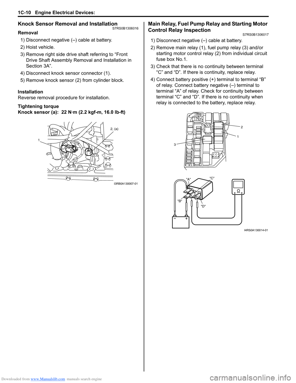
Knock Sensor Removal and InstallationS7RS0B1306016
Removal1) Disconnect negative (–) cable at battery.
2) Hoist vehicle.
3) Remove right side drive shaft referring to “Front Drive Shaft Assembly Removal and Installation in
Section 3A”.
4) Disconnect knock sensor connector (1).
5) Remove knock sensor (2) from cylinder block.
Installation
Reverse removal procedure for installation.
Tightening torque
Knock sensor (a): 22 N· m (2.2 kgf-m, 16.0 lb-ft)
Main Relay, Fuel Pump Relay and Starting Motor
Control Relay Inspection
S7RS0B1306017
1) Disconnect negative (–) cable at battery.
2) Remove main relay (1), fuel pump relay (3) and/or
starting motor control relay (2) from individual circuit
fuse box No.1.
3) Check that there is no continuity between terminal “C” and “D”. If there is continuity, replace relay.
4) Connect battery positive (+ ) terminal to terminal “B”
of relay. Connect battery negative (–) terminal to
terminal “A” of relay. Ch eck for continuity between
terminal “C” and “D”. If t here is no continuity when
relay is connected to the battery, replace relay.
1 2, (a)
I3RB0A130007-01
"D"
"B" "A"
"C"
2
1
3
I4RS0A130014-01
Page 286 of 1496
Downloaded from www.Manualslib.com manuals search engine 1D-1 Engine Mechanical:
Engine
Engine Mechanical
General Description
Engine Construction DescriptionS7RS0B1401001
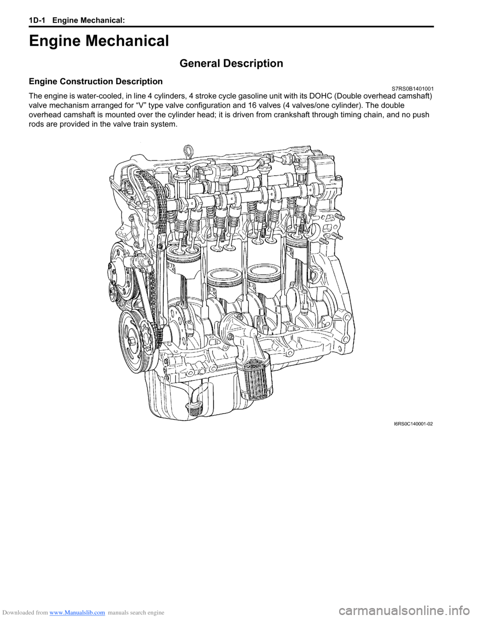
The engine is water-cooled, in line 4 cylinders, 4 stroke cycle gasoline unit with its DOHC (Double overhead camshaft)
valve mechanism arranged for “V” type valve configurat ion and 16 valves (4 valves/one cylinder). The double
overhead camshaft is mounted over the cy linder head; it is driven from crankshaft through timing chain, and no push
rods are provided in the valve train system.
I6RS0C140001-02
Page 302 of 1496

Downloaded from www.Manualslib.com manuals search engine 1D-17 Engine Mechanical:
Engine Assembly Removal and InstallationS7RS0B1406011
NOTE
After replacing electric throttle body
assembly, perform calibration of throttle
valve referring to “Electric Throttle Body
System Calibration in Section 1C”.
Removal1) Relieve fuel pressure according to “Fuel Pressure Relief Procedure in Section 1G”.
2) Disconnect negative and pos itive cable at battery.
3) Remove battery and tray.
4) Remove engine hood after disconnecting windshield washer hose.
5) Remove right and left side engine under covers.
6) Remove A/C compressor belt by referring to “Compressor Drive Belt Remo val and Installation in
Section 7B” or “Compressor Drive Belt Removal and
Installation in Section 7B”.
7) Drain engine oil, transaxle oil and coolant.
8) Remove cowl top plate referring to “Cowl Top Components in Section 9K”.
9) Remove air cleaner assembly referring to “Air Cleaner Components”.
10) With hose connected, detach A/C compressor from its bracket (A/C model) referring to “Compressor
Assembly Removal and Installation in Section 7B” or
“Compressor Assembly Removal and Installation in
Section 7B”.
CAUTION!
Suspend removed A/C compressor at a place
where no damage will be caused during
removal and installation of engine assembly.
11) Remove intake manifold rear stiffener (1) from intake manifold and cylinder block. 12) Disconnect the following electric wires:
• MAP sensor (1)
• ECT sensor (2)
•EGR valve (3)
• CMP sensor (4)
• Electric throttle body assembly (5)
• Ignition coil assembly (6)
• Injectors (7)
• Heated oxygen sensor No. 2 (8) and No. 1 (9)
• Oil control valve (10)
• Engine oil pressure switch (11)
• CKP sensor (12)
• Knock sensor (13)
• Back up light switch (14)
• Generator (15)
• Starting motor (16)
• Ground terminal (17) from intake manifold
• Battery ground terminal (18) from exhaust manifold
• Battery ground cable (19) from transaxle
• Magnet clutch switch of A/C compressor (A/C model)
• Each wire harness clamps
• Output shaft speed sensor (VSS) (34) (A/T model)
• Solenoid valve (33) (A/T model)
• Transmission range sensor (32) (A/T model)
• Input shaft speed sensor (31) (A/T model)
13) Remove fuse box from its bracket.
14) Disconnect the following cables: • Gear select control cable (23) (M/T model)
• Gear shift control cable (24) (M/T model)
• A/T select cable (A/T model)
15) Disconnect the following hoses: • Brake booster hose (26) from intake manifold
• Radiator inlet and outlet hoses (20) from each pipe
• Heater inlet and outlet hoses (21) from each pipe
• Fuel feed hoses (22) from fuel feed pipe
• EVAP canister purge valve hose (30) from purge pipe
• A/T fluid cooler hoses (A/T model)
16) With hose connected, detach clutch operating cylinder (25). (M/T model)
CAUTION!
Suspend removed clutch operating cylinder
at a place where no damage will be caused
during removal and installation of engine
assembly.
1
I6RS0B141014-01
Page 303 of 1496

Downloaded from www.Manualslib.com manuals search engine Engine Mechanical: 1D-18
17) Disconnect right and left drive shaft joints from differential gear referring to “Front Drive Shaft
Assembly Removal and Installation in Section 3A”.
NOTE
For engine and transaxle removal, it is not
necessary to remove drive shafts from
steering knuckle.
18) Remove exhaust No.1, No.2 and center pipes referring to “Exhaust Pipe and Muffler Removal and
Installation in Section 1K”.
19) Support engine assemble by using chain hoist.
20) Remove suspension frame referring to “Front Suspension Frame, Stabiliz er Bar and/or Bushings
Removal and Installati on in Section 2B”.
21) Remove engine rear mounting from engine rear mounting No.1 bracket.
22) Support engine and transaxle with jack, and then remove chain hoist.
23) Remove engine left mounting bracket nuts (1) and engine right mounting nuts (2).
[A]: M/T model
[B]: A/T model
7
26
30
5
4
22
3
2
20
6
9
18
8
11
10
21 1
16
17
151213
[B]
23
24
14
25 19
34
33
32
32
31
[A]
I6RS0C140028-01
1
2
I4RS0A140008-01