2005 SUZUKI SWIFT Inspection of ecm
[x] Cancel search: Inspection of ecmPage 275 of 1496

Downloaded from www.Manualslib.com manuals search engine Engine Electrical Devices: 1C-3
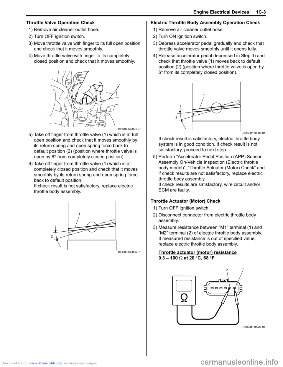
Throttle Valve Operation Check1) Remove air cleaner outlet hose.
2) Turn OFF ignition switch.
3) Move throttle valve with finger to its full open position and check that it moves smoothly.
4) Move throttle valve with fi nger to its completely
closed position and check that it moves smoothly.
5) Take off finger from throttle valve (1) which is at full open position and check that it moves smoothly by
its return spring and open spring force back to
default position (2) (positio n where throttle valve is
open by 6 ° from completely closed position).
6) Take off finger from throttle valve (1) which is at completely closed position and check that it moves
smoothly by its return spring and open spring force
back to default position.
If check result is not satisfactory, replace electric
throttle body assembly. Electric Throttle Body
Assembly Operation Check
1) Remove air cleaner outlet hose.
2) Turn ON ignition switch.
3) Depress accelerator pedal gradually and check that throttle valve moves smoo thly until it opens fully.
4) Release accelerator pedal depressed in Step 3) and check that throttle valve (1) moves back to default
position (2) (position where throttle valve is open by
6° from its completely closed position).
If check result is satisfactory, electric throttle body
system is in good condition. If check result is not
satisfactory, proceed to next step.
5) Perform “Accelerator Pe dal Position (APP) Sensor
Assembly On-Vehicle Inspection (Electric throttle
body model)”, “Throttle Actuator (Motor) Check” and
if check results are not satisfactory, replace electric
throttle body assembly.
If check results are satisfactory, wire circuit and/or
ECM are faulty.
Throttle Actuator (Motor) Check 1) Turn OFF ignition switch.
2) Disconnect connector from electric throttle body assembly.
3) Measure resistance between “M1” terminal (1) and “M2” terminal (2) of electric throttle body assembly.
If measured resistance is out of specified value,
replace electric throttle body assembly.
Throttle actuator (motor) resistance
0.3 – 100 Ω at 20 °C, 68 °F
I4RS0B130004-01
1
2
I4RS0B130005-01
1
2
I4RS0B130005-01
2 1
I4RS0B130023-01
Page 277 of 1496

Downloaded from www.Manualslib.com manuals search engine Engine Electrical Devices: 1C-5
Electric Throttle Body System CalibrationS7RS0B1306004
NOTE
If working the service described under the
“Precautions of Electric Throttle Body
System Calibration in Section 1A” perform
following steps for electric throttle body
system calibration.
1) If electric throttle body assembly and/or APP sensor
assembly are replaced, perform following steps.
a) Disconnect negative cable at battery for 20 seconds or more for the purpose of clearing
calibration data of closed throttle position from
memory in ECM.
b) Connect negative cable to battery.
2) Keep ignition switch at ON position for 5 seconds or more without running engine.
APP Sensor Assembly On-Vehicle InspectionS7RS0B1306005
1) Check that APP sensor a ssembly has been mounted
to vehicle body properly (no pinched floor carpet,
etc.).
If mounting is not pro perly, reinstall APP sensor
assembly properly refe rring to “APP Sensor
Assembly Removal and Installation”.
2) Connect scan tool to DLC with ignition switch turned OFF.
3) Turn ON ignition switch and select “Data List” mode on scan tool.
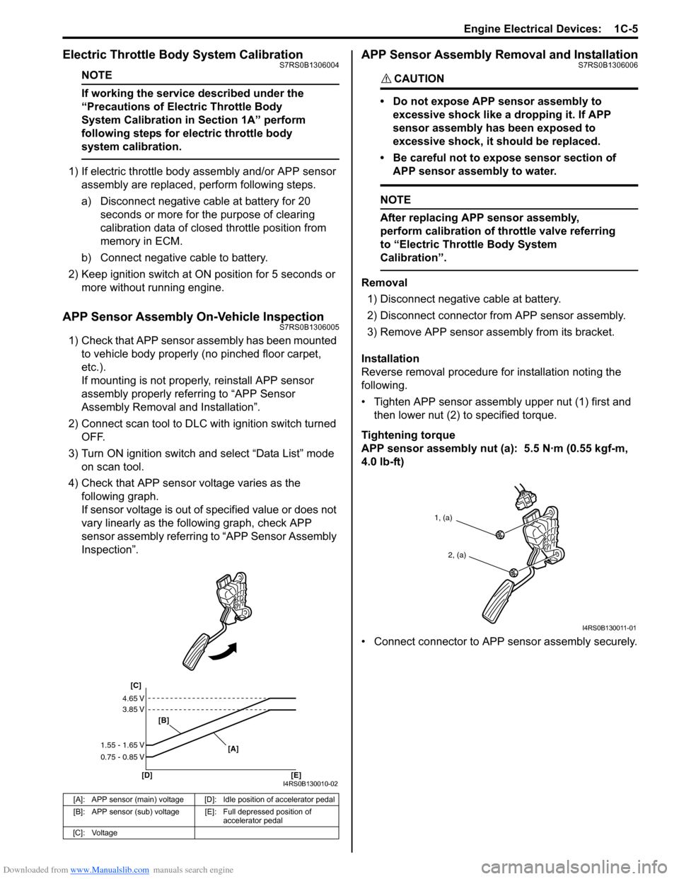
4) Check that APP sensor voltage varies as the following graph.
If sensor voltage is out of specified value or does not
vary linearly as the fo llowing graph, check APP
sensor assembly referring to “APP Sensor Assembly
Inspection”.
APP Sensor Assembly Removal and InstallationS7RS0B1306006
CAUTION!
• Do not expose APP sensor assembly to
excessive shock like a dropping it. If APP
sensor assembly has been exposed to
excessive shock, it should be replaced.
• Be careful not to expose sensor section of APP sensor assembly to water.
NOTE
After replacing APP sensor assembly,
perform calibration of th rottle valve referring
to “Electric Throttle Body System
Calibration”.
Removal
1) Disconnect negative cable at battery.
2) Disconnect connector from APP sensor assembly.
3) Remove APP sensor asse mbly from its bracket.
Installation
Reverse removal procedure for installation noting the
following.
• Tighten APP sensor assembly upper nut (1) first and then lower nut (2) to specified torque.
Tightening torque
APP sensor assembly nut (a): 5.5 N·m (0.55 kgf-m,
4.0 lb-ft)
• Connect connector to APP sensor assembly securely.
[A]: APP sensor (main) voltage [D]: Idle position of accelerator pedal
[B]: APP sensor (sub) voltage [E]: Full depressed position of
accelerator pedal
[C]: Voltage
[C]
[B]
[D] [E] [A]
4.65 V
3.85 V
1.55 - 1.65 V
0.75 - 0.85 V
I4RS0B130010-02
1, (a)
2, (a)
I4RS0B130011-01
Page 283 of 1496

Downloaded from www.Manualslib.com manuals search engine Engine Electrical Devices: 1C-11
MAF and IAT Sensor On-Vehicle InspectionS7RS0B1306018
NOTE
Before performed this inspection, be sure to
read the “Precautions of ECM Circuit
Inspection in Section 1A”.
1) Disconnect negative (–) cable at battery.
2) Disconnect MAF and IAT sensor connector.
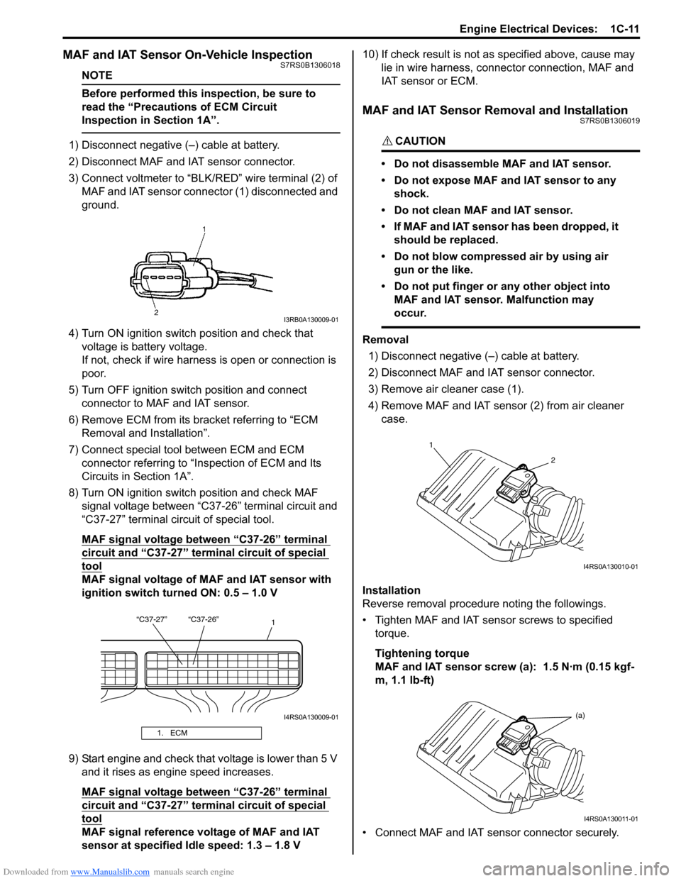
3) Connect voltmeter to “BLK/RED” wire terminal (2) of
MAF and IAT sensor connector (1) disconnected and
ground.
4) Turn ON ignition switch position and check that voltage is battery voltage.
If not, check if wire harness is open or connection is
poor.
5) Turn OFF ignition switch position and connect connector to MAF and IAT sensor.
6) Remove ECM from its bracket referring to “ECM Removal and Installation”.
7) Connect special tool between ECM and ECM connector referring to “Inspection of ECM and Its
Circuits in Section 1A”.
8) Turn ON ignition switch position and check MAF signal voltage between “C37-26” terminal circuit and
“C37-27” terminal circuit of special tool.
MAF signal voltage between “C37-26” terminal
circuit and “C37-27” termi nal circuit of special
tool
MAF signal voltage of MAF and IAT sensor with
ignition switch turned ON: 0.5 – 1.0 V
9) Start engine and check that voltage is lower than 5 V and it rises as engine speed increases.
MAF signal voltage between “C37-26” terminal
circuit and “C37-27” termi nal circuit of special
tool
MAF signal reference voltage of MAF and IAT
sensor at specified Idle speed: 1.3 – 1.8 V 10) If check result is not as
specified above, cause may
lie in wire harness, connec tor connection, MAF and
IAT sensor or ECM.
MAF and IAT Sensor Removal and InstallationS7RS0B1306019
CAUTION!
• Do not disassemble MAF and IAT sensor.
• Do not expose MAF and IAT sensor to any shock.
• Do not clean MAF and IAT sensor.
• If MAF and IAT sensor has been dropped, it should be replaced.
• Do not blow compressed air by using air gun or the like.
• Do not put finger or any other object into MAF and IAT sensor. Malfunction may
occur.
Removal
1) Disconnect negative (–) cable at battery.
2) Disconnect MAF and IAT sensor connector.
3) Remove air cleaner case (1).
4) Remove MAF and IAT sensor (2) from air cleaner case.
Installation
Reverse removal procedure noting the followings.
• Tighten MAF and IAT sensor screws to specified torque.
Tightening torque
MAF and IAT sensor screw (a): 1.5 N·m (0.15 kgf-
m, 1.1 lb-ft)
• Connect MAF and IAT sensor connector securely.
1. ECM
I3RB0A130009-01
“C37-27” “C37-26” 1
I4RS0A130009-01
1
2
I4RS0A130010-01
(a)
I4RS0A130011-01
Page 285 of 1496

Downloaded from www.Manualslib.com manuals search engine Engine Electrical Devices: 1C-13
Without Using SUZUKI Scan Tool1) Measure sensor voltage between “C37-23” terminal of ECM connector and vehicle body ground referring
to “Inspection of ECM and Its Circuits in Section 1A”.
If check result is satisfactory, electric load current
sensor is in good condition.
If check result is not satisfactory, check the following
parts and circuit.
• Electric load current sensor circuit (power, ground and output)
• Following charging system components – Battery (refer to “Battery Inspection in Section
1J”)
– Generator (refer to “Generator Inspection in Section 1J”)
– Generator output control circuit (refer to “Generator Test (Undercharged Battery Check)
in Section 1J”)
– Generator field coil monitor circuit (refer to “Generator Inspection in Section 1J”) If electric load current sensor circuit and charging
system is in good condition,
electric load current sensor
(1) is faulty.
Specifications
Tightening Torque SpecificationsS7RS0B1307001
Reference:
For the tightening torque of fastener not specified in this section, refer to “Fasteners Information in Section 0A”.
2. Main fuse box
2
1
I5RS0C130001-01
Fastening part
Tightening torque
Note
N ⋅mkgf-mlb-ft
ECM mounting bolt 8 0.8 6.0 �)
APP sensor assembly nut 5.5 0.55 4.0 �)
ECT sensor 15 1.5 11.0 �)
Heated oxygen sensor 45 4.5 32.5 �)
CMP sensor bolt 10 1.0 7.5 �)
CKP sensor bolt 10 1.0 7.5 �)
Knock sensor 22 2.2 16.0 �)
MAF and IAT sensor screw 1.5 0.15 1.1 �)
Page 377 of 1496

Downloaded from www.Manualslib.com manuals search engine Fuel System: 1G-2
Fuel Pump DescriptionS7RS0B1701003
The fuel pump (1) is an in-tank type electric pump.
Incorporated in the pump assembly are;
a fuel filter (2) and a fuel pressure regulator (3) are
included and a fuel level gauge (4) is attached.
Addition of the fuel pressure regulator to the fuel pump
makes it possible to mainta in the fuel pressure at
constant level and ECM controls compensation for
variation in the intake manifold pressure.
Schematic and Routing Diagram
Fuel Delivery System DiagramS7RS0B1702001
Diagnostic Information and Procedures
Fuel Pressure InspectionS7RS0B1704001
WARNING!
Before starting the following procedure, be
sure to observe “Precautions on Fuel System
Service” in order to reduce the risk or fire
and personal injury.
1) Relieve fuel pressure in fuel feed line referring to
“Fuel Pressure Relief Procedure”.
2) Disconnect fuel feed hose from fuel delivery pipe.
3) Connect special tools and hose between fuel feed hose (1) and fuel delivery pipe as shown in figure,
and clamp hoses securely in order to ensure that no
leaks occur during checking.
Special tool
(A): 09912–58442
(B): 09912–58432
(C): 09912–58490
1
3
2
4
I6RS0C170001-01
4
6 7
8
12
2 3
11
10
5
1
9
I6RS0C170002-01
1. Fuel tank
5. Fuel injector9. EVAP canister
2. Fuel pump 6. Fuel feed line10. Fuel filter
3. Fuel pressure regulator 7. Fuel vapor line 11. Main fuel level sensor
4. Delivery pipe 8. Intake manifold12. EVAP canister purge valve
1
(C) (B)
(A)
I3RM0A170004-01
Page 382 of 1496

Downloaded from www.Manualslib.com manuals search engine 1G-7 Fuel System:
Fuel Pressure Relief ProcedureS7RS0B1706003
CAUTION!
This work must not be done when engine is
hot. If done so, it may cause adverse effect to
catalyst.
NOTE
If ECM detects DTC(s) after servicing, clear
DTC(s) referring to “DTC Clearance in
Section 1A”.
1) Make sure that engine is cold.
2) Shift transaxle gear shift lever in “Neutral” (shift select lever in “P” range for A/T model), set parking
brake and block drive wheels.
3) Remove relay / fuse box cover.
4) Disconnect fuel pump relay (1) from relay / fuse box (2).
5) Remove fuel filter cap in order to release fuel vapor pressure in fuel tank, and then reinstall it.
6) Start engine and run it until engine stops for lack of fuel. Repeat cranking engine 2 – 3 times for about 3
seconds each time in order to dissipate fuel pressure
in lines. Fuel connections are now safe for servicing.
7) After servicing, connect fuel pump relay (1) to relay / fuse box and install re lay / fuse box cover.
Fuel Leakage Check ProcedureS7RS0B1706004
After performing any service on fuel system, check to
make sure that there are no fuel leakages as follows.
1) Turn ON ignition switch for 3 seconds (to operate fuel pump) and then turn it OFF.
Repeat this (ON and OFF) 3 or 4 times and apply
fuel pressure to fuel line until fuel pressure is felt by
hand placed on fuel feed hose.
2) In this state, check to see that there are no fuel leakages from any part of fuel system.
Fuel Lines On-Vehicle InspectionS7RS0B1706005
CAUTION!
Due to the fact that fuel feed line (1) is under
high pressure, use special care when
servicing it.
Visually inspect fuel lines for evidence of fuel leakage,
hose crack and deterioration or damage.
Make sure all cl amps are secure.
Replace parts as needed.
Fuel Pipe Removal and InstallationS7RS0B1706006
WARNING!
Before starting the following procedure, be
sure to observe “Precautions on Fuel System
Service” in order to reduce the risk or fire
and personal injury.
Removal
1) Relieve fuel pressure in fuel feed line according to “Fuel Pressure Relief Procedure”.
2) Disconnect negative cable at battery.
3) Disconnect fuel pipe joint and fuel hose (3) from fuel pipe (2) at the front and rear of each fuel pipe
referring to “Fuel Hose Disconnecting and
Reconnecting”.
4) Mark the location of clamps (1) on fuel pipes (2), so that the clamps can be reinstalled to where they
were.
5) Remove pipes (2) with clamp (1) from vehicle.
6) Remove clamp (1) from pipes (2).
1
I4RS0A170004-01
1
I4RS0A170005-01
2
13
I4RS0A170020-01
Page 385 of 1496

Downloaded from www.Manualslib.com manuals search engine Fuel System: 1G-10
4) Install suitable vinyl tube onto injector nozzle to
prevent fuel from splashing out when injecting.
5) Put graduated cylinder under injector.
6) Operate fuel pump and apply fuel pressure to
injector as follows:
a) When using scan tool:
i) Connect scan tool to DLC with ignition switch OFF.
ii) Turn ignition switch ON, clear DTC and select “MISC TEST” mode on scan tool.
iii) Turn fuel pump ON by using scan tool.
Special tool
(A): SUZUKI scan tool
b) When not using scan tool: i) Remove fuel pump relay from connector.
ii) Connect two terminals of relay connector using service wire (1) as shown in figure.
CAUTION!
Check to make sure that connection is made
between correct terminals. Wrong
connection can cause damage to ECM, wire
harness, etc.
iii) Turn ignition switch ON. 7) Apply battery voltage to in
jector (1) for 15 seconds
and measure injected fuel volume with graduated
cylinder. Test each injector two or three times. If not
within specification, replace injector.
Injected fuel volume
43 – 47 cc/15 sec. (1.45/1.51 – 1.58/1.65 US/lmp
oz/15 sec.)
8) Check fuel leakage from injector nozzle. Do not operate injector for this check (but fuel pump should
be at work). If fuel leaks (1) more than the following
specifications, replace.
Fuel leakage
Less than 1 drop/min.
Fuel Filler Cap InspectionS7RS0B1706010
WARNING!
Before starting the following procedure, be
sure to observe “Precautions on Fuel System
Service” in order to reduce the risk or fire
and personal injury.
Remove cap (1), and che ck gasket for even filler neck
imprint, and deterioration or any damage. If gasket (2) is
in malcondition, replace cap.
NOTE
If cap requires replacement, only a cap with
the same features should be used. Failure to
use correct cap can result in fire and
personal injury.
(A)I4RS0A170021-01
1
I4RS0A170006-02
I2RH0B170013-01
I2RH01170008-01
Page 396 of 1496

Downloaded from www.Manualslib.com manuals search engine 1H-4 Ignition System:
Diagnostic Information and Procedures
Ignition System Symptom DiagnosisS7RS0B1804001
Reference Waveform of Ignition SystemS7RS0B1804002
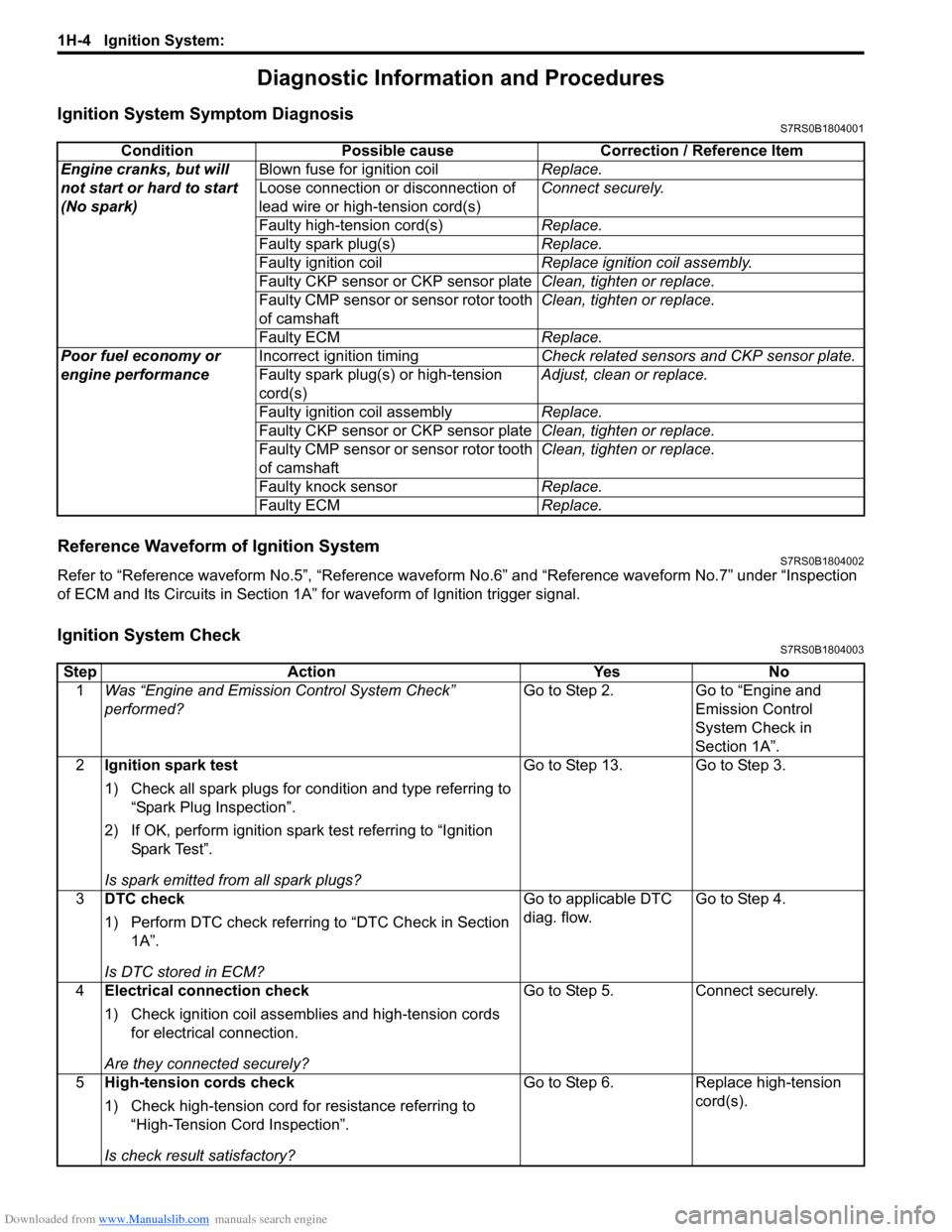
Refer to “Reference waveform No.5”, “Reference waveform No.6” and “Reference waveform No.7” under “Inspection
of ECM and Its Circuits in Section 1A” for waveform of Ignition trigger signal.
Ignition System CheckS7RS0B1804003
Condition Possible cause Correction / Reference Item
Engine cranks, but will
not start or hard to start
(No spark) Blown fuse for ignition coil
Replace.
Loose connection or disconnection of
lead wire or high-tension cord(s) Connect securely.
Faulty high-tension cord(s) Replace.
Faulty spark plug(s) Replace.
Faulty ignition coil Replace ignition coil assembly.
Faulty CKP sensor or CKP sensor plate Clean, tighten or replace.
Faulty CMP sensor or sensor rotor tooth
of camshaft Clean, tighten or replace.
Faulty ECM Replace.
Poor fuel economy or
engine performance Incorrect ignition timing
Check related sensors and CKP sensor plate.
Faulty spark plug(s) or high-tension
cord(s) Adjust, clean or replace.
Faulty ignition coil assembly Replace.
Faulty CKP sensor or CKP sensor plate Clean, tighten or replace.
Faulty CMP sensor or sensor rotor tooth
of camshaft Clean, tighten or replace.
Faulty knock sensor Replace.
Faulty ECM Replace.
StepAction YesNo
1 Was “Engine and Emission Control System Check”
performed? Go to Step 2.
Go to “Engine and
Emission Control
System Check in
Section 1A”.
2 Ignition spark test
1) Check all spark plugs for condition and type referring to
“Spark Plug Inspection”.
2) If OK, perform ignition spark test referring to “Ignition Spar k Tes t”.
Is spark emitted from all spark plugs? Go to Step 13. Go to Step 3.
3 DTC check
1) Perform DTC check referring to “DTC Check in Section
1A”.
Is DTC stored in ECM? Go to applicable DTC
diag. flow.
Go to Step 4.
4 Electrical connection check
1) Check ignition coil assemblies and high-tension cords
for electrical connection.
Are they connected securely? Go to Step 5.
Connect securely.
5 High-tension cords check
1) Check high-tension cord for resistance referring to
“High-Tension Cord Inspection”.
Is check result satisfactory? Go to Step 6.
Replace high-tension
cord(s).