2005 SUZUKI SWIFT power supply jb
[x] Cancel search: power supply jbPage 1093 of 1496
Downloaded from www.Manualslib.com manuals search engine Air Bag System: 8B-55
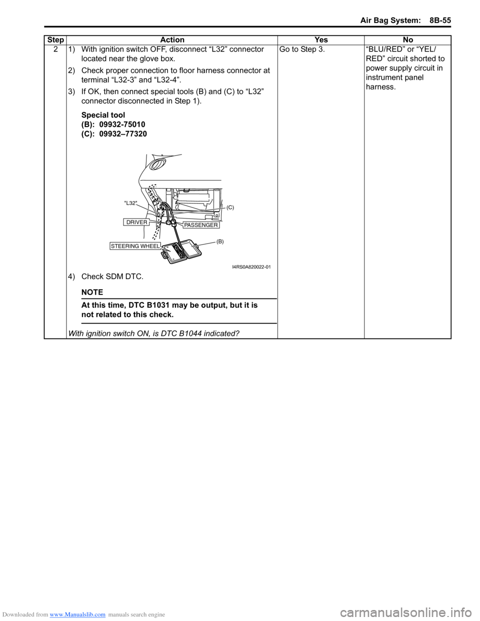
2 1) With ignition switch OFF, disconnect “L32” connector located near the glove box.
2) Check proper connection to floor harness connector at terminal “L32-3” and “L32-4”.
3) If OK, then connect special tools (B) and (C) to “L32” connector disconnected in Step 1).
Special tool
(B): 09932-75010
(C): 09932–77320
4) Check SDM DTC.
NOTE
At this time, DTC B1031 ma y be output, but it is
not related to this check.
With ignition switch ON , is DTC B1044 indicated? Go to Step 3. “BLU/RED” or “YEL/
RED” circuit shorted to
power supply circuit in
instrument panel
harness.
Step Action Yes No
(B) (C)
"L32"STEERING WHEEL
DRIVERPASSENGER
I4RS0A820022-01
Page 1094 of 1496
Downloaded from www.Manualslib.com manuals search engine 8B-56 Air Bag System:
NOTE
Upon completion of inspection and repair work, perform the following items.
• Reconnect all air bag system components and ensure all components are properly mounted.
• Clear DTCs referring to “DTC Clearance”, if any.
• Repeat “Air Bag Diagnostic System Check” to confirm that the trouble has been corrected.
DTC B1051 / B1055: Driver / Passenger Pretensioner Initiator Circuit Resistance HighS7RS0B8204026
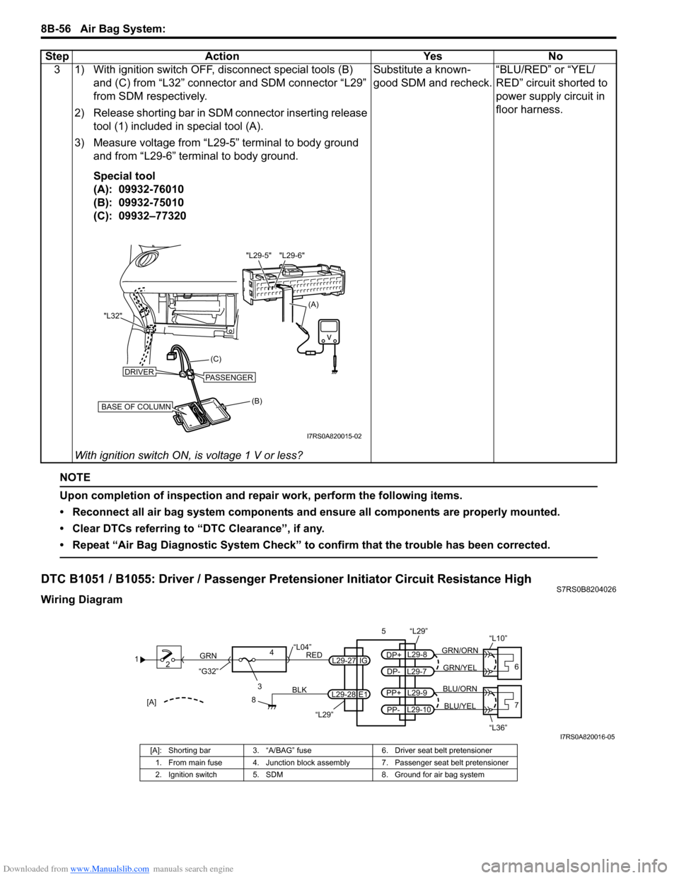
Wiring Diagram3 1) With ignition switch OFF, disconnect special tools (B)
and (C) from “L32” connector and SDM connector “L29”
from SDM respectively.
2) Release shorting bar in SDM connector inserting release tool (1) included in special tool (A).
3) Measure voltage from “L29-5” terminal to body ground and from “L29-6” terminal to body ground.
Special tool
(A): 09932-76010
(B): 09932-75010
(C): 09932–77320
With ignition switch ON, is voltage 1 V or less? Substitute a known-
good SDM and recheck.
“BLU/RED” or “YEL/
RED” circuit shorted to
power supply circuit in
floor harness.
Step Action Yes No
(B)
(C)
"L32"
BASE OF COLUMN
DRIVERPASSENGER
(A)
"L29-6"
"L29-5"
I7RS0A820015-02
1
2
3
GRN
RED
8
BLK
L29-27
L29-28 IG
E1
4
“L29”
“L04”
“G32”
“L29”
L29-8
DP+
L29-7
DP-GRN/YEL
GRN/ORN
56
“L10”
L29-9
PP+
L29-10
PP-BLU/YEL
BLU/ORN7
“L36”[A]
I7RS0A820016-05
[A]: Shorting bar 3. “A/BAG” fuse 6. Driver seat belt pretensioner
1. From main fuse 4. Junction block assembly 7. Passenger seat belt pretensioner
2. Ignition switch 5. SDM 8. Ground for air bag system
Page 1102 of 1496
Downloaded from www.Manualslib.com manuals search engine 8B-64 Air Bag System:
NOTE
Upon completion of inspection and repair work, perform the following items.
• Reconnect all air bag system components and ensure all components are properly mounted.
• Clear DTCs referring to “DTC Clearance”, if any.
• Repeat “Air Bag Diagnostic System Check” to confirm that the trouble has been corrected.
DTC B1061 / B1065: Driver / Passenger Side-Air Bag Initiator Circuit Resistance HighS7RS0B8204030
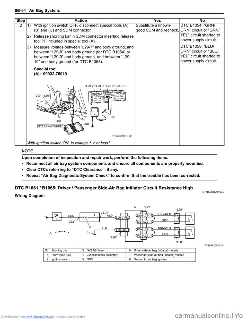
Wiring Diagram2 1) With ignition switch OFF, disconnect special tools (A),
(B) and (C) and SDM connector.
2) Release shorting bar in SDM connector inserting release tool (1) included in special tool (A).
3) Measure voltage between “L29-7” and body ground, and between “L29-8” and body ground (for DTC B1054) or
between “L29-9” and body ground, and between “L29-
10” and body ground (for DTC B1058).
Special tool
(A): 09932-76010
With ignition switch ON, is voltage 1 V or less? Substitute a known-
good SDM and recheck.
DTC B1054: “GRN/
ORN” circuit or “GRN/
YEL” circuit shorted to
power supply circuit.
DTC B1058: “BLU/
ORN” circuit or “BLU/
YEL” circuit shorted to
power supply circuit.
Step Action Yes No
"L29-8" "L29-9" "L29-10"
"L29-7"
(A)
STEERING WHEEL(B)
(C)
(A)
"L10", "L36"
I7RS0A820019-02
1
2
3
GRN
RED
8
BLK
L29-27
L29-28 IG
E1
4
“L29”
“L04”
“G32”
“L29”
L29-12
DS+
L29-11
DS-GRY
GRY/RED
56
“L25”
L29-13
PS+
L29-14
PS-BRN
BRN/WHT7
“L30”[A]
I7RS0A820020-04
[A]: Shorting bar 3. “A/BAG” fuse 6. Driver side-air bag (inflator) module
1. From main fuse 4. Junction block assembly 7. Passenger side-air bag (inflator) module
2. Ignition switch 5. SDM 8. Ground for air bag system
Page 1116 of 1496
Downloaded from www.Manualslib.com manuals search engine 8B-78 Air Bag System:
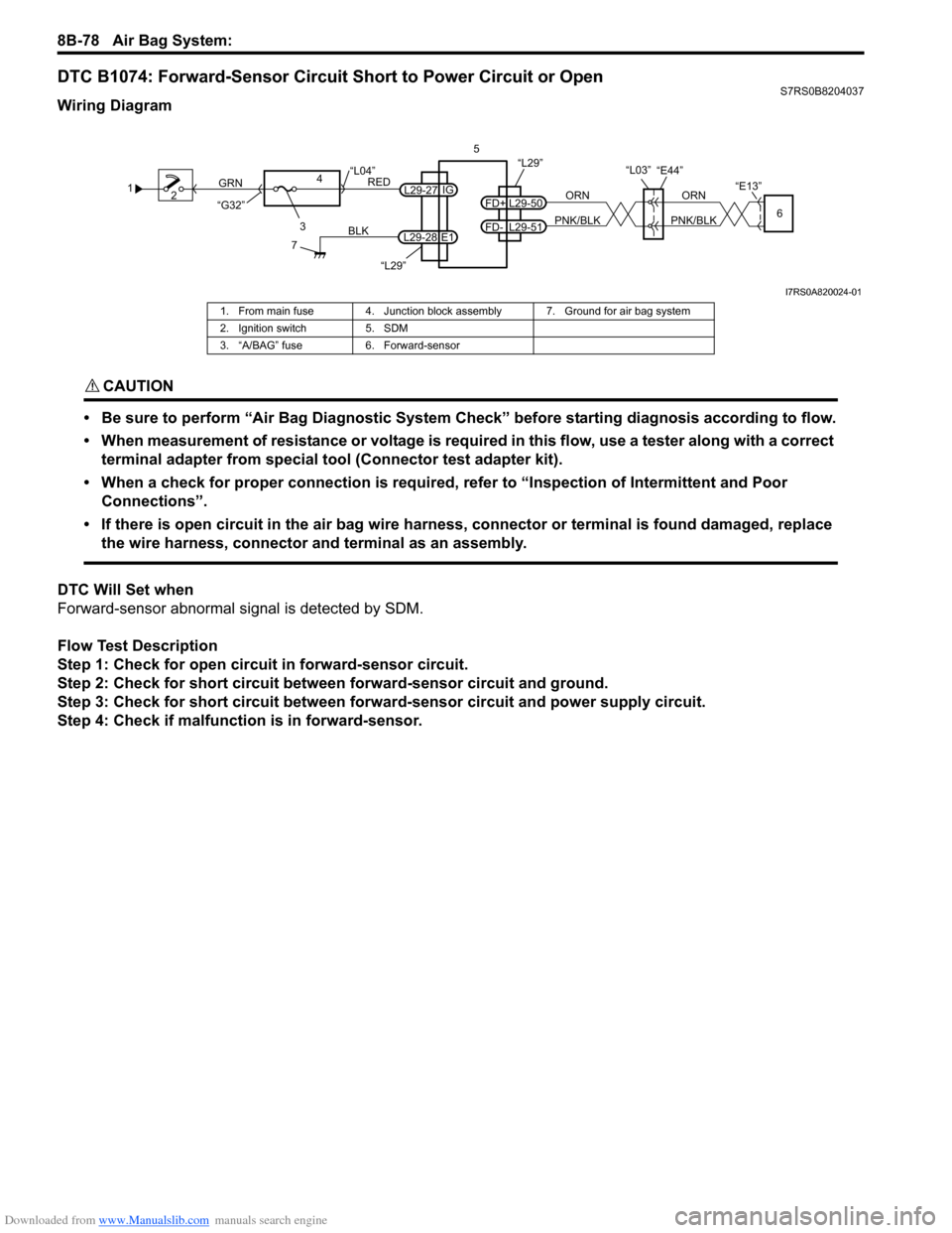
DTC B1074: Forward-Sensor Circuit Short to Power Circuit or OpenS7RS0B8204037
Wiring Diagram
CAUTION!
• Be sure to perform “Air Bag Diagnostic System Check” before starting diagnosis according to flow.
• When measurement of resistance or voltage is required in this flow, use a tester along with a correct terminal adapter from special tool (Connector test adapter kit).
• When a check for proper connection is required, refer to “Inspection of Intermittent and Poor Connections”.
• If there is open circuit in the air bag wire harnes s, connector or terminal is found damaged, replace
the wire harness, connector and terminal as an assembly.
DTC Will Set when
Forward-sensor abnormal signal is detected by SDM.
Flow Test Description
Step 1: Check for open circuit in forward-sensor circuit.
Step 2: Check for short circuit between forward-sensor circuit and ground.
Step 3: Check for short circuit between forw ard-sensor circuit and power supply circuit.
Step 4: Check if malfuncti on is in forward-sensor.
1
2
3
GRN
RED
7
BLK
L29-27
L29-28 IG
E1
4
“L29”
“L04”
“G32”
“L29”5
ORN
PNK/BLK
ORN
PNK/BLKL29-50
FD+
L29-51
FD-6
“E13”
“L03”“E44”
I7RS0A820024-01
1. From main fuse 4. Junction block assembly 7. Ground for air bag system
2. Ignition switch 5. SDM
3. “A/BAG” fuse 6. Forward-sensor
Page 1117 of 1496
Downloaded from www.Manualslib.com manuals search engine Air Bag System: 8B-79
DTC Troubleshooting
NOTE
Upon completion of inspection and repair work, perform the following items.
• Reconnect all air bag system components and ensure all components are properly mounted.
• Clear DTCs referring to “DTC Clearance”, if any.
• Repeat “Air Bag Diagnostic System Check” to confirm that the trouble has been corrected.
StepAction YesNo
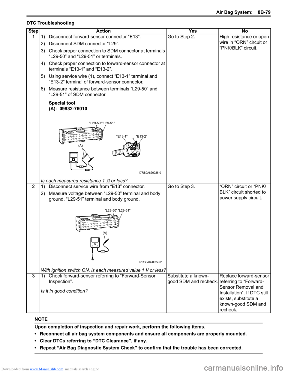
1 1) Disconnect forward-sensor connector “E13”.
2) Disconnect SDM connector “L29”.
3) Check proper connection to SDM connector at terminals “L29-50” and “L29-51” or terminals.
4) Check proper connection to forward-sensor connector at terminals “E13-1” and “E13-2”.
5) Using service wire (1), connect “E13-1” terminal and “E13-2” terminal of forward-sensor connector.
6) Measure resistance between terminals “L29-50” and “L29-51” of SDM connector.
Special tool
(A): 09932-76010
Is each measured resistance 1
Ω or less? Go to Step 2. High resistance or open
wire in “ORN” circuit or
“PNK/BLK” circuit.
2 1) Disconnect service wire from “E13” connector. 2) Measure voltage between “L29-50” terminal and body ground, “L29-51” terminal and body ground.
With ignition switch ON, is each measured value 1 V or less? Go to Step 3. “ORN” circuit or “PNK/
BLK” circuit shorted to
power supply circuit.
3 1) Check forward-sensor referring to “Forward-Sensor Inspection”.
Is it in good condition? Substitute a known-
good SDM and recheck.
Replace forward-sensor
referring to “Forward-
Sensor Removal and
Installation”. If DTC still
exists, substitute a
known-good SDM and
recheck.
(A)
"L29-50" "L29-51"
"E13-1" "E13-2"1
I7RS0A820026-01
"L29-50" "L29-51"
(A)
I7RS0A820027-01
Page 1120 of 1496
Downloaded from www.Manualslib.com manuals search engine 8B-82 Air Bag System:
CAUTION!
• Be sure to perform “Air Bag Diagnostic System Check” before starting diagnosis according to flow.
• When measurement of resistance or voltage is required in this flow, use a tester along with a correct terminal adapter from special tool (Connector test adapter kit).
• When a check for proper connection is required, refer to “Inspection of Intermittent and Poor Connections”.
• If there is open circuit in the air bag wire harnes s, connector or terminal is found damaged, replace
the wire harness, connector and terminal as an assembly.
DTC Will Set when
The resistance measured between side-sensor circuit and power source circuit is below a specified value for specified
time.
Flow Test Description
Step 1: Check for open circuit in side-sensor circuit.
Step 2: Check for short circuit between side-sensor circuit and power supply circuit.
Step 3: Check if malfunction is in side-sensor.
DTC Troubleshooting
Step Action YesNo
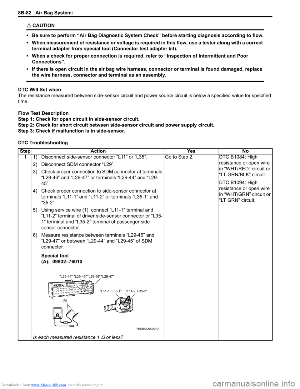
1 1) Disconnect side-sensor connector “L11” or “L35”.
2) Disconnect SDM connector “L29”.
3) Check proper connection to SDM connector at terminals “L29-46” and “L29-47” or terminals “L29-44” and “L29-
45”.
4) Check proper connection to side-sensor connector at terminals “L11-1” and “L11-2” or terminals “L35-1” and
“35-2”.
5) Using service wire (1), connect “L11-1” terminal and “L11-2” terminal of driver side-sensor connector or “L35-
1” terminal and “L35-2” terminal of passenger side-
sensor connector.
6) Measure resistance between terminals “L29-46” and “L29-47” or between “L29-44” and “L29-45” of SDM
connector.
Special tool
(A): 09932–76010
Is each measured resistance 1
Ω or less? Go to Step 2. DTC B1084: High
resistance or open wire
in “WHT/RED” circuit or
“LT GRN/BLK” circuit.
DTC B1094: High
resistance or open wire
in “WHT/GRN” circuit or
“LT GRN” circuit.
(A)
"L11-1, L35-1" "L11-2, L35-2"1
"L29-45" "L29-46" "L29-47"
"L29-44"
I7RS0A820029-01
Page 1121 of 1496
Downloaded from www.Manualslib.com manuals search engine Air Bag System: 8B-83
NOTE
Upon completion of inspection and repair work, perform the following items.
• Reconnect all air bag system components and ensure all components are properly mounted.
• Clear DTCs referring to “DTC Clearance”, if any.
• Repeat “Air Bag Diagnostic System Check” to confirm that the trouble has been corrected.
DTC B1085 / B1095: Wrong Side-Sensor (Driver Side / Passenger) IDS7RS0B8204042
DTC Will Set when
SDM receives wrong ID (Part No.) signal from side-sensor.
DTC Troubleshooting1) Turn ignition switch OFF.
2) Replace driver or passenger side-sensor referr ing to “Side-Sensor Removal and Installation”.
3) Repeat “Air Bag Diagnostic System Check”.
NOTE
Upon completion of inspection and repair work, perform the following items.
• Reconnect all air bag system components and ensure all components are properly mounted.
• Clear DTCs referring to “DTC Clearance”, if any.
• Repeat “Air Bag Diagnostic System Check” to confirm that the trouble has been corrected.
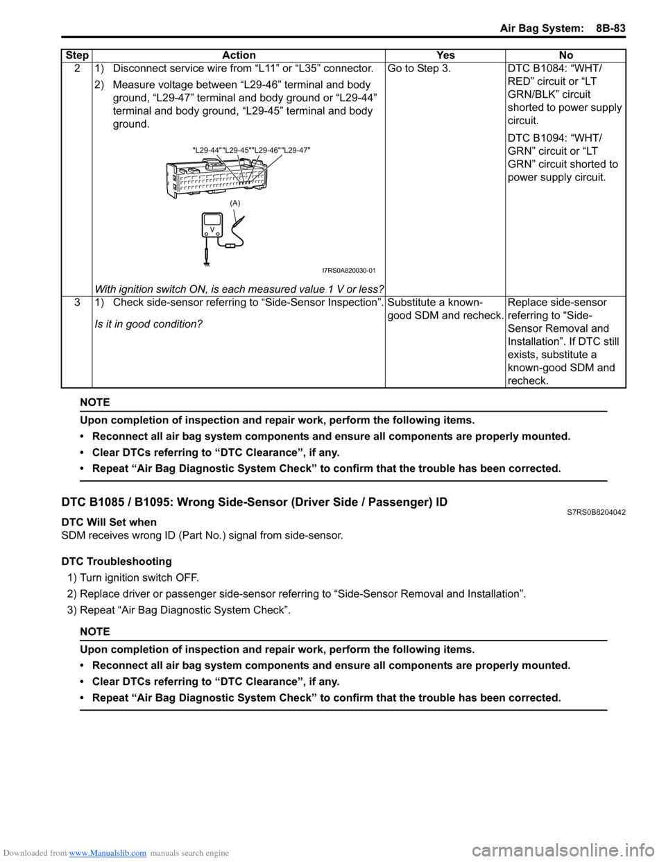
2 1) Disconnect service wire from “L11” or “L35” connector.
2) Measure voltage between “L29-46” terminal and body ground, “L29-47” terminal and body ground or “L29-44”
terminal and body ground, “L29-45” terminal and body
ground.
With ignition switch ON, is each measured value 1 V or less? Go to Step 3. DTC B1084: “WHT/
RED” circuit or “LT
GRN/BLK” circuit
shorted to power supply
circuit.
DTC B1094: “WHT/
GRN” circuit or “LT
GRN” circuit shorted to
power supply circuit.
3 1) Check side-sensor referring to “Side-Sensor Inspection”. Is it in good condition? Substitute a known-
good SDM and recheck.
Replace side-sensor
referring to “Side-
Sensor Removal and
Installation”. If DTC still
exists, substitute a
known-good SDM and
recheck.
Step Action Yes No
(A)
"L29-45""L29-46" "L29-47"
"L29-44"
I7RS0A820030-01
Page 1167 of 1496

Downloaded from www.Manualslib.com manuals search engine Table of Contents 9- i
9
Section 9
CONTENTS
Body, Cab and Accessories
Precautions ................................................. 9-1
Precautions............................................................. 9-1
Precautions on Body, Cab and Accessories ......... 9-1
Precautions for Body Service ................................ 9-1
Fastener Caution for Body Service ....................... 9-1
Wiring Systems............... ......................... 9A-1
Precautions........................................................... 9A-1
Cautions in Body Electrical System Servicing..... 9A-1
General Description ............................................. 9A-1 Abbreviations ...................................................... 9A-1
Wire / Connector Color Sy mbols ......................... 9A-1
Symbols and Marks ............................................ 9A-2
How to Read Connector Layout Diagram ........... 9A-4
How to Read Connector Codes and Terminal Nos.................................................................... 9A-5
How to Read Ground Point ................................. 9A-7
How to Read Power Supply Diagram.................. 9A-8
How to Read System Circuit Diagram................. 9A-8
Connector Layout Diagram . .............................. 9A-10
Connector Layout Diagram ............................... 9A-10
Engine Compartment .......... .............................. 9A-10
Instrument Panel ............................................... 9A-16
Door, Roof......................................................... 9A-20
Floor .................................................................. 9A-23
Rear .................................................................. 9A-29
Ground Point ...................................................... 9A-30 Ground (earth) Point ......................................... 9A-30
Power Supply Diagram ........ .............................. 9A-31
Power Supply Diagram ....... .............................. 9A-31
Fuses and the Protected Parts ......................... 9A-33
Fuses in Main Fuse Box (RHD) ........................ 9A-33
Fuses in Main Fuse Box (LHD) ......................... 9A-33
Individual Circuit Fuse Box No. 1 ...................... 9A-34
Individual Circuit Fuse Box No. 2 (In J/B) ......... 9A-35
Junction Block (J/B) Connector / Fuse Layout .. 9A-37
Junction Block Inner Circuit (Overview) ............ 9A-38
Junction Block Inner Circuit (Detail) .................. 9A-40
System Circuit Diagram... .................................. 9A-45
System Circuit Diagram .. .................................. 9A-45
A-1 Cranking System Circ uit Diagram .............. 9A-46
A-2 Charging System Circu it Diagram .............. 9A-47
A-3 Ignition System Circu it Diagram ................. 9A-48
A-4 Cooling System Circuit Diagram................. 9A-49 A-5 Engine and A/C Control System Circuit
Diagram........................................................... 9A-50
A-6 A/T Control System Circuit Diagram........... 9A-55
A-7 Immobilizer System Circuit Diagram .......... 9A-57
A-8 Body Control System Circuit Diagram ........ 9A-58
B-1 Windshield Wiper and Washer Circuit Diagram........................................................... 9A-62
B-2 Rear Wiper and Washer Circuit Diagram ... 9A-63
B-3 Rear Defogger Circuit Diagram .................. 9A-64
B-4 Power Window Circuit Diagram .................. 9A-65
B-5 Power Door Lock Circu it Diagram .............. 9A-67
B-6 Power Mirror Circuit Diagram ..................... 9A-69
B-7 Horn Circuit Diagram .................................. 9A-70
B-8 Seat Heater Circuit Diagram....................... 9A-71
B-9 Keyless Start System Circuit Diagram........ 9A-72
C-1 Combination Mete r Circuit Diagram
(Meter)............................................................. 9A-73
C-2 Combination Mete r Circuit Diagram
(Indicator) ........................................................ 9A-74
C-3 Combination Mete r Circuit Diagram
(Warning Light)................................................ 9A-75
D-1 Headlight System Circuit Diagram ............. 9A-77
D-2 Position, Tail and Licence Plate Light System Circuit Diagram .................................. 9A-79
D-3 Front Fog Light System Circuit Diagram .... 9A-80
D-4 Illumination Light System Circuit Diagram .. 9A-81
D-5 Interior Light System Circuit Diagram......... 9A-82
D-6 Turn Signal and Hazard Warning Light System Circuit Diagram .................................. 9A-83
D-7 Brake Light System Circuit Diagram .......... 9A-85
D-8 Back-Up Light System Circuit Diagram ...... 9A-86
D-9 Headlight Beam Leveling System Circuit Diagram........................................................... 9A-87
D-10 Rear Fog Light Circuit Diagram ................ 9A-88
E-1 Heater System Circuit Diagram .................. 9A-89
E-2 Auto A/C System Circuit Diagram .............. 9A-91
F-1 Air-Bag System Circuit Diagram ................. 9A-93
F-2 Anti-Lock Brake System Circuit Diagram.... 9A-95
F-3 Electronic Stab ility Program System
Circuit Diagram .................. ............................. 9A-97
F-4 Power Steering System Circuit Diagram .... 9A-99
G-1 Audio System Circuit Diagram ................. 9A-101
G-2 Multi Information Display / Accessory Socket System Circuit Diagram .................... 9A-102
List of Connector .............................................9A-103