2005 SUZUKI SWIFT power supply jb
[x] Cancel search: power supply jbPage 1002 of 1496
Downloaded from www.Manualslib.com manuals search engine 7B-54 Air Conditioning System: Automatic Type
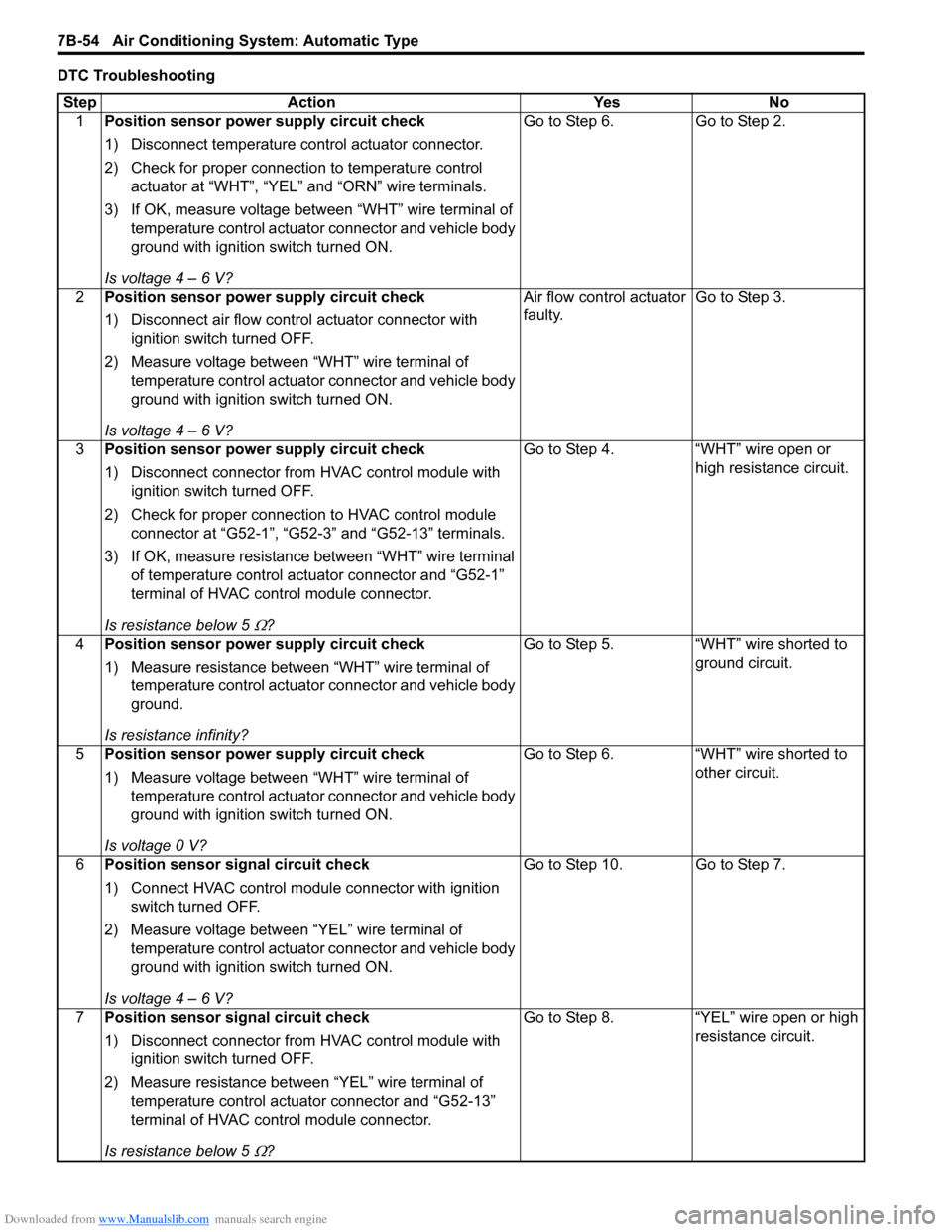
DTC TroubleshootingStep Action YesNo
1 Position sensor power supply circuit check
1) Disconnect temperature control actuator connector.
2) Check for proper connection to temperature control
actuator at “WHT”, “YEL” and “ORN” wire terminals.
3) If OK, measure voltage between “WHT” wire terminal of temperature control actuator connector and vehicle body
ground with ignition switch turned ON.
Is voltage 4 – 6 V? Go to Step 6.
Go to Step 2.
2 Position sensor power supply circuit check
1) Disconnect air flow control actuator connector with
ignition switch turned OFF.
2) Measure voltage between “WHT” wire terminal of temperature control actuator connector and vehicle body
ground with ignition switch turned ON.
Is voltage 4 – 6 V? Air flow control actuator
faulty.
Go to Step 3.
3 Position sensor power supply circuit check
1) Disconnect connector from HVAC control module with
ignition switch turned OFF.
2) Check for proper connection to HVAC control module connector at “G52-1”, “G52-3” and “G52-13” terminals.
3) If OK, measure resistance between “WHT” wire terminal of temperature control actuator connector and “G52-1”
terminal of HVAC control module connector.
Is resistance below 5
Ω? Go to Step 4. “WHT” wire open or
high resistance circuit.
4 Position sensor power supply circuit check
1) Measure resistance between “WHT” wire terminal of
temperature control actuator connector and vehicle body
ground.
Is resistance infinity? Go to Step 5.
“WHT” wire shorted to
ground circuit.
5 Position sensor power supply circuit check
1) Measure voltage between “WHT” wire terminal of
temperature control actuator connector and vehicle body
ground with ignition switch turned ON.
Is voltage 0 V? Go to Step 6.
“WHT” wire shorted to
other circuit.
6 Position sensor signal circuit check
1) Connect HVAC control module connector with ignition
switch turned OFF.
2) Measure voltage between “YEL” wire terminal of temperature control actuator connector and vehicle body
ground with ignition switch turned ON.
Is voltage 4 – 6 V? Go to Step 10. Go to Step 7.
7 Position sensor signal circuit check
1) Disconnect connector from HVAC control module with
ignition switch turned OFF.
2) Measure resistance between “YEL” wire terminal of temperature control actuator connector and “G52-13”
terminal of HVAC control module connector.
Is resistance below 5
Ω? Go to Step 8. “YEL” wire open or high
resistance circuit.
Page 1004 of 1496
Downloaded from www.Manualslib.com manuals search engine 7B-56 Air Conditioning System: Automatic Type
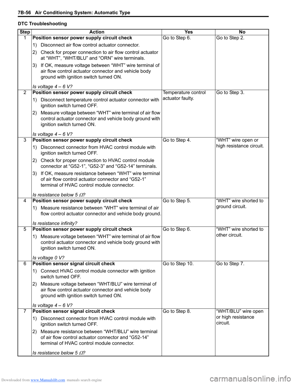
DTC TroubleshootingStep Action YesNo
1 Position sensor power supply circuit check
1) Disconnect air flow control actuator connector.
2) Check for proper connection to air flow control actuator
at “WHT”, “WHT/BLU” and “ORN” wire terminals.
3) If OK, measure voltage between “WHT” wire terminal of air flow control actuator connector and vehicle body
ground with ignition switch turned ON.
Is voltage 4 – 6 V? Go to Step 6.
Go to Step 2.
2 Position sensor power supply circuit check
1) Disconnect temperature control actuator connector with
ignition switch turned OFF.
2) Measure voltage between “WHT” wire terminal of air flow control actuator connector and vehicle body ground with
ignition switch turned ON.
Is voltage 4 – 6 V? Temperature control
actuator faulty.
Go to Step 3.
3 Position sensor power supply circuit check
1) Disconnect connector from HVAC control module with
ignition switch turned OFF.
2) Check for proper connection to HVAC control module connector at “G52-1”, “G52-3” and “G52-14” terminals.
3) If OK, measure resistance between “WHT” wire terminal of air flow control actuator connector and “G52-1”
terminal of HVAC control module connector.
Is resistance below 5
Ω? Go to Step 4. “WHT” wire open or
high resistance circuit.
4 Position sensor power supply circuit check
1) Measure resistance between “WHT” wire terminal of air
flow control actuator connector and vehicle body ground.
Is resistance infinity? Go to Step 5. “WHT” wire shorted to
ground circuit.
5 Position sensor power supply circuit check
1) Measure voltage between “WHT” wire terminal of air flow
control actuator connector and vehicle body ground with
ignition switch turned ON.
Is voltage 0 V? Go to Step 6. “WHT” wire shorted to
other circuit.
6 Position sensor signal circuit check
1) Connect HVAC control module connector with ignition
switch turned OFF.
2) Measure voltage between “WHT/BLU” wire terminal of air flow control actuator connector and vehicle body
ground with ignition switch turned ON.
Is voltage 4 – 6 V? Go to Step 10. Go to Step 7.
7 Position sensor signal circuit check
1) Disconnect connector from HVAC control module with
ignition switch turned OFF.
2) Measure resistance between “WHT/BLU” wire terminal of air flow control actuator connector and “G52-14”
terminal of HVAC control module connector.
Is resistance below 5
Ω? Go to Step 8. “WHT/BLU” wire open
or high resistance
circuit.
Page 1010 of 1496
Downloaded from www.Manualslib.com manuals search engine 7B-62 Air Conditioning System: Automatic Type
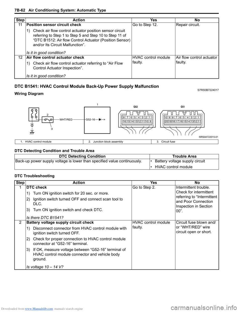
DTC B1541: HVAC Control Module Back-Up Power Supply MalfunctionS7RS0B7224017
Wiring Diagram
DTC Detecting Condition and Trouble Area
DTC Troubleshooting11
Position sensor circuit check
1) Check air flow control actuator position sensor circuit
referring to Step 1 to Step 5 and Step 10 to Step 11 of
“DTC B1512: Air flow Control Actuator (Position Sensor)
and/or Its Circuit Malfunction”.
Is it in good condition? Go to Step 12. Repair circuit.
12 Air flow control actuator check
1) Check air flow control actuator referring to “Air Flow
Control Actuator Inspection”.
Is it in good condition? HVAC control module
faulty.
Air flow control actuator
faulty.
Step Action Yes No
WHT/RED
2 17812910
65 431516 14 13 12 11
G52
789101920121112
65 431718 16 15 14 13
G51
3
G52-16
I5RS0A722015-01
1. HVAC control module
2. Junction block assembly 3. Circuit fuse
DTC Detecting Condition Trouble Area
Back-up power supply voltage is lo wer than specified value continuously. • Battery voltage supply circuit
• HVAC control module
StepAction YesNo
1 DTC check
1) Turn ON ignition switch for 20 sec. or more.
2) Ignition switch turned OF F and connect scan tool to
DLC.
3) Turn ON ignition switch and check DTC.
Is there DTC B1541? Go to Step 2.
Intermittent trouble.
Check for intermittent
referring to “Intermittent
and Poor Connection
Inspection in Section
00”.
2 Battery voltage supply circuit check
1) Disconnect connector from HVAC control module with
ignition switch turned OFF.
2) Check for proper connection to HVAC control module connector at “G52-16” terminal.
3) If OK, measure voltage between “G52-16” terminal of HVAC control module connector and vehicle body
ground.
Is voltage 10 – 14 V? HVAC control module
faulty.
Circuit fuse blown and/
or “WHT/RED” wire
circuit open or short.
Page 1019 of 1496
Downloaded from www.Manualslib.com manuals search engine Air Conditioning System: Automatic Type 7B-71
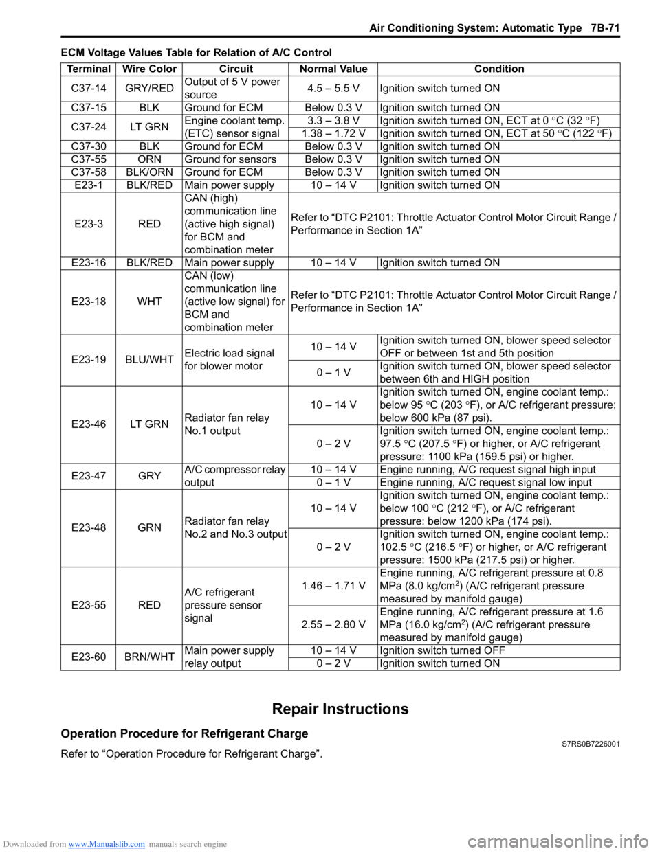
ECM Voltage Values Table for Relation of A/C Control
Repair Instructions
Operation Procedure for Refrigerant ChargeS7RS0B7226001
Refer to “Operation Procedure for Refrigerant Charge”.Terminal Wire Color Circuit Normal Value Condition
C37-14 GRY/RED Output of 5 V power
source 4.5 – 5.5 V Ignition switch turned ON
C37-15 BLK Ground for ECM Below 0.3 V Ignition switch turned ON
C37-24 LT GRN Engine coolant temp.
(ETC) sensor signal 3.3 – 3.8 V Ignition switch turned ON, ECT at 0
°C (32 ° F)
1.38 – 1.72 V Ignition switch turned ON, ECT at 50 °C (122 °F)
C37-30 BLK Ground for ECM Below 0.3 V Ignition switch turned ON
C37-55 ORN Ground for sensors Below 0.3 V Ignition switch turned ON
C37-58 BLK/ORN Ground for ECM Below 0.3 V Ignition switch turned ON E23-1 BLK/RED Main power supply 10 – 14 V Ignition switch turned ON
E23-3 RED CAN (high)
communication line
(active high signal)
for BCM and
combination meterRefer to “DTC P2101: Throttle Actu
ator Control Motor Circuit Range /
Performance in Section 1A”
E23-16 BLK/RED Main power supply 10 – 14 V Ignition switch turned ON
E23-18 WHT CAN (low)
communication line
(active low signal) for
BCM and
combination meterRefer to “DTC P2101: Throttle Actu
ator Control Motor Circuit Range /
Performance in Section 1A”
E23-19 BLU/WHT Electric load signal
for blower motor 10 – 14 V
Ignition switch turned ON, blower speed selector
OFF or between 1st and 5th position
0 – 1 V Ignition switch turned ON, blower speed selector
between 6th and HIGH position
E23-46 LT GRN Radiator fan relay
No.1 output 10 – 14 V
Ignition switch turned ON, engine coolant temp.:
below 95
°C (203 ° F), or A/C refrigerant pressure:
below 600 kPa (87 psi).
0 – 2 V Ignition switch turned ON, engine coolant temp.:
97.5
°C (207.5 °F) or higher, or A/C refrigerant
pressure: 1100 kPa (159.5 psi) or higher.
E23-47 GRY A/C compressor relay
output 10 – 14 V Engine running, A/C request signal high input
0 – 1 V Engine running, A/C request signal low input
E23-48 GRN Radiator fan relay
No.2 and No.3 output 10 – 14 V
Ignition switch turned ON, engine coolant temp.:
below 100
°C (212 °F), or A/C refrigerant
pressure: below 1200 kPa (174 psi).
0 – 2 V Ignition switch turned ON, engine coolant temp.:
102.5
°C (216.5 ° F) or higher, or A/C refrigerant
pressure: 1500 kPa (217.5 psi) or higher.
E23-55 RED A/C refrigerant
pressure sensor
signal 1.46 – 1.71 V
Engine running, A/C refrigerant pressure at 0.8
MPa (8.0 kg/cm
2) (A/C refrigerant pressure
measured by manifold gauge)
2.55 – 2.80 V Engine running, A/C refrigerant pressure at 1.6
MPa (16.0 kg/cm
2) (A/C refrigerant pressure
measured by manifold gauge)
E23-60 BRN/WHT Main power supply
relay output 10 – 14 V Ignition switch turned OFF
0 – 2 V Ignition switch turned ON
Page 1051 of 1496
Downloaded from www.Manualslib.com manuals search engine Air Bag System: 8B-13
Scan Tool DataS7RS0B8204006
Data list of SDM
Definition
Back Up Volt (V)
This parameter indicates the capacity of the backup
condenser installed to maintain the ignition current (as
much as possible) even when the power supply to SDM
that ignites the inflator is shut off.
Battery Voltage (V)
Battery voltage is an analog input signal read by SDM.
System ID (4ch/8ch)
This parameter indicates the number of initiator circuits.
Driv A/B Ini Res (Driver air bag initiator resistance)
(ohm)
This parameter indicates the resistance of the driver air
bag initiator circuit. Pass A/B Ini Res (Passenger air bag initiator
resistance) (ohm)
This parameter indicates the
resistance of the passenger
air bag initiator circuit.
Driv Preten Ini Res (Dri ver pretensioner initiator
resistance) (ohm)
This parameter indicates the resistance of the driver seat
belt pretensioner initiator circuit.
Pass Preten Ini Res (Passenger pretensioner
initiator resistance) (ohm)
This parameter indicates the resistance of the passenger
seat belt pretensioner initiator circuit.
Driv Sidebag Ini Res (Driver side-air bag initiator
resistance) (ohm)
This parameter indicates the resistance of the driver
side-air bag initiator circuit.
Pass Sidebag Ini Res (Passenger side-air bag
initiator resistance) (ohm)
This parameter indicates the resistance of the
Passenger side-air bag initiator circuit.
Driv curtain Ini Res (Driver side curtain-air bag
initiator resistance) (ohm)
This parameter indicates the re sistance of the driver side
curtain-air bag initiator circuit.
Pass curtain Ini Res (Passenger side curtain-air bag
initiator resistance) (ohm)
This parameter indicates the resistance of the passenger
side curtain-air bag initiator circuit.
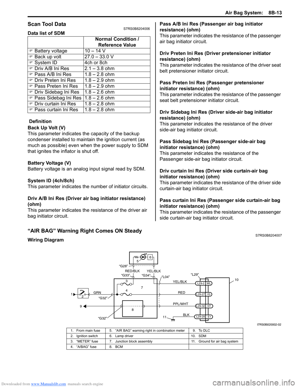
“AIR BAG” Warning Right Comes ON SteadyS7RS0B8204007
Wiring Diagram Normal Condition /
Reference Value
�) Battery voltage 10 – 14 V
�) Back up volt 27.0 – 33.0 V
�) System ID 4ch or 8ch
�) Driv A/B Ini Res 2.1 – 3.8 ohm
�) Pass A/B Ini Res 1.8 – 2.8 ohm
�) Driv Preten Ini Res 1.8 – 2.9 ohm
�) Pass Preten Ini Res 1.8 – 2.9 ohm
�) Driv Sidebag Ini Res 1.8 – 2.6 ohm
�) Pass Sidebag Ini Res 1.8 – 2.6 ohm
�) Driv curtain Ini Res 1.8 – 2.8 ohm
�) Pass curtain Ini Res 1.8 – 2.8 ohm
1
2 GRN
11
BLK
L29-27
L29-2
L29-28 WL
E1
IG
L29-32
ST
10
8
“L29”
RED
PPL/WHT
7
3
4 “L04”
“G34”
“G33”
“G28”
“G32”
5 6
“G32”
YEL/BLK
YEL/BLK
RED/BLK
9
I7RS0B820002-02
1. From main fuse 5. “AIR BAG” warning right in combination meter 9. To DLC
2. Ignition switch 6. Lamp driver 10. SDM
3. “METER” fuse 7. Junction block assembly 11. Ground for air bag system
4. “A/BAG” fuse 8. BCM
Page 1052 of 1496
Downloaded from www.Manualslib.com manuals search engine 8B-14 Air Bag System:
CAUTION!
• Be sure to perform “Air Bag Diagnostic System Check” before starting diagnosis according to flow.
• When measurement of resistance or voltage is required in this flow, use a tester along with a correct terminal adapter from special tool (Connector test adapter kit).
• When a check for proper connection is required, refer to “Inspection of Intermittent and Poor Connections”.
• If there is open circuit in the air bag wire harnes s, connector or terminal is found damaged, replace
the wire harness, connector and terminal as an assembly.
Flow Test Description
Step 1: Check for “A/BAG” fuse blown.
Step 2, 3: Check for loose connection between junction block assembly connector and junction block
assembly.
Step 4: Check for loose connection between SDM connector and SDM.
Step 5: Check for SDM power supply circuit.
Step 6: Check for short circuit between “A IR BAG” warning right circuit and ground.
Troubleshooting Step Action YesNo
1 1) Turn ignition switch OFF.
2) Remove and inspect “A/BAG” fuse.
Is fuse good? Go to Step 2.
“RED” wire short to
ground.
After repair, replace “A/
BAG” fuse.
2 1) Check for loose connection of junction block assembly connector “L04”.
Is it connected securely? Go to Step 3.
Correct connector “L04”
securely.
3 1) Check for loose connection of junction block assembly connector “G34”.
Is it connected securely? Go to Step 4.
Correct connector “G34”
securely.
4 1) Check for loose connection of SDM connector “L29”. Is it connected securely? Go to Step 5.
Correct connector “L29”
securely.
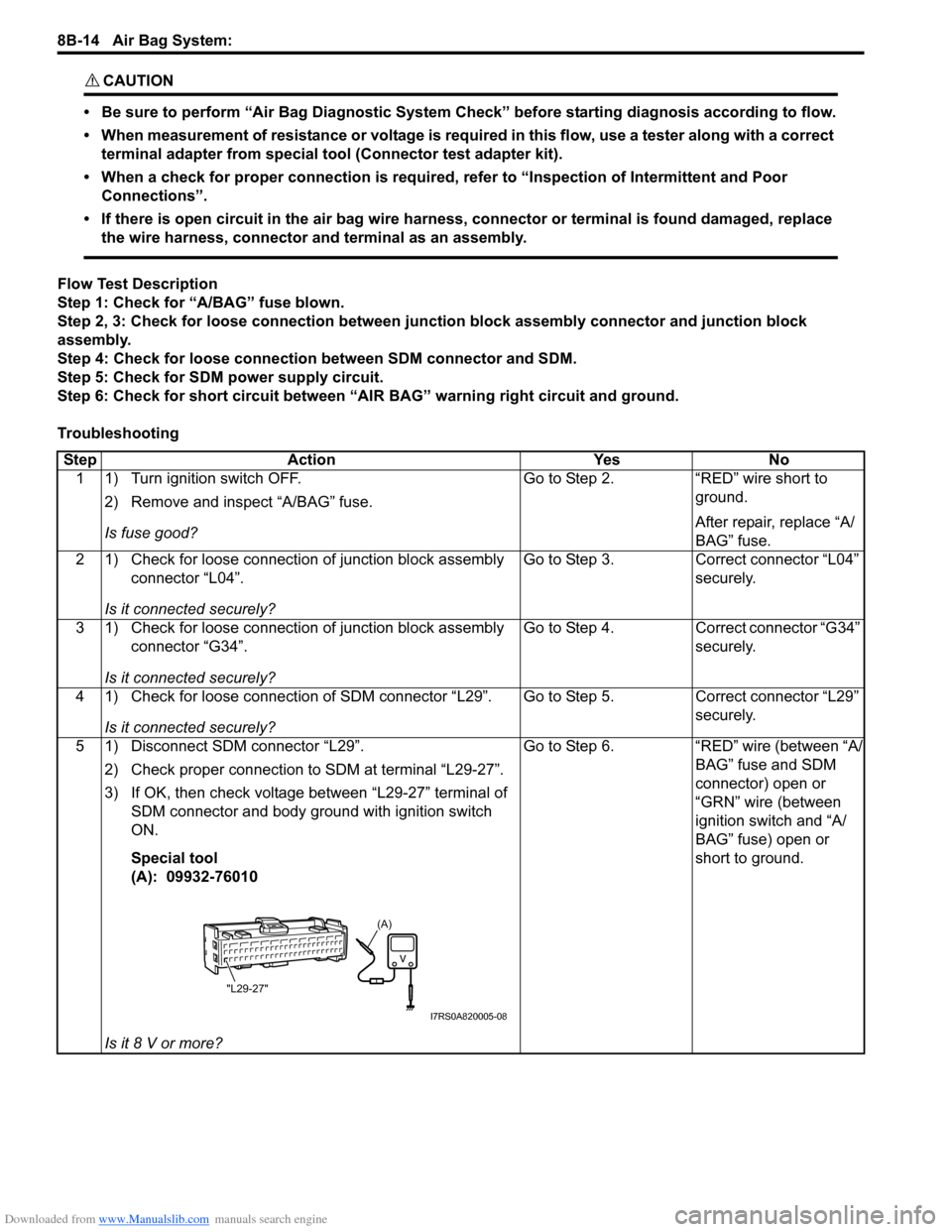
5 1) Disconnect SDM connector “L29”. 2) Check proper connection to SDM at terminal “L29-27”.
3) If OK, then check voltage between “L29-27” terminal of SDM connector and body ground with ignition switch
ON.
Special tool
(A): 09932-76010
Is it 8 V or more? Go to Step 6.
“RED” wire (between “A/
BAG” fuse and SDM
connector) open or
“GRN” wire (between
ignition switch and “A/
BAG” fuse) open or
short to ground.
(A)
"L29-27"
I7RS0A820005-08
Page 1079 of 1496
Downloaded from www.Manualslib.com manuals search engine Air Bag System: 8B-41
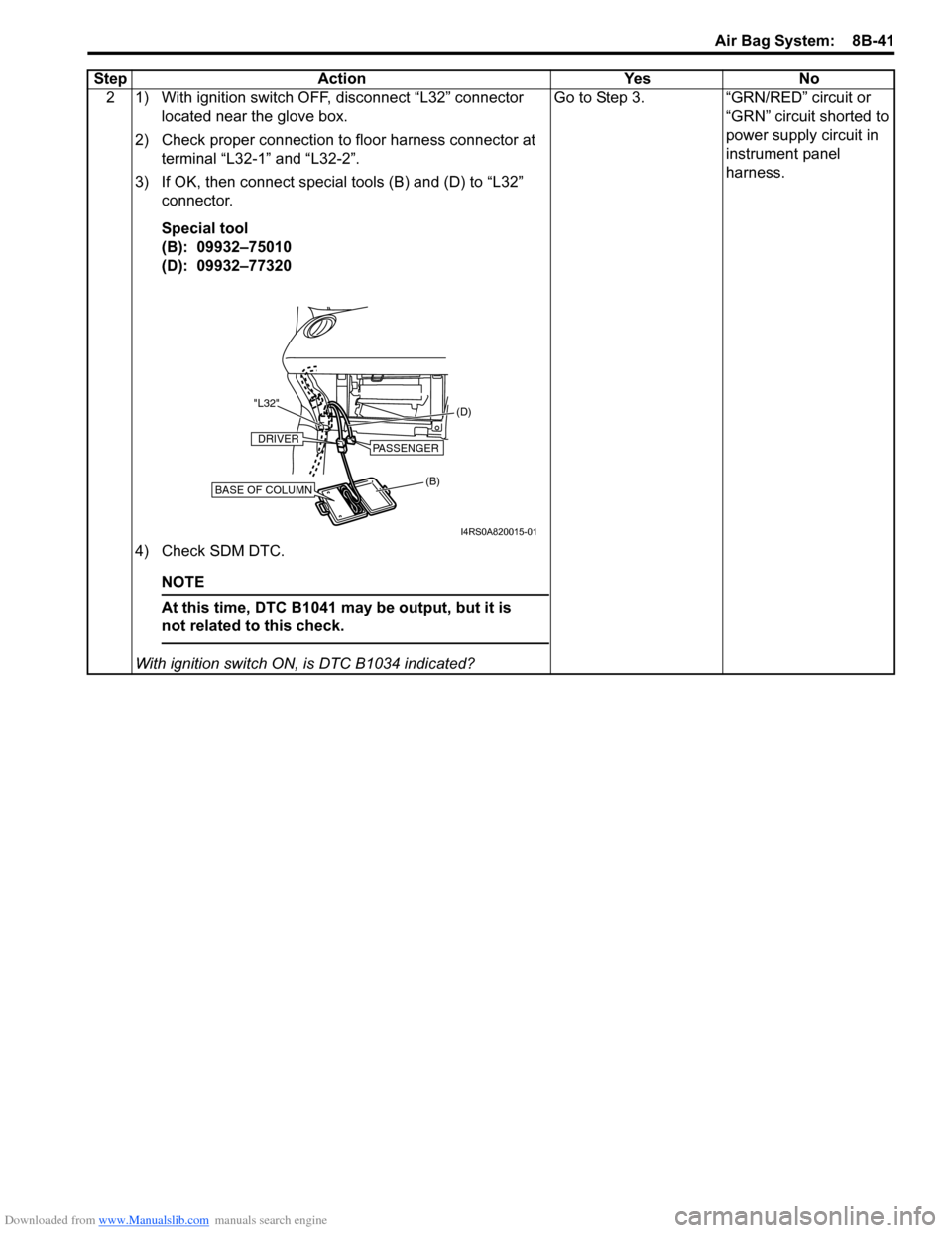
2 1) With ignition switch OFF, disconnect “L32” connector located near the glove box.
2) Check proper connection to floor harness connector at terminal “L32-1” and “L32-2”.
3) If OK, then connect special tools (B) and (D) to “L32” connector.
Special tool
(B): 09932–75010
(D): 09932–77320
4) Check SDM DTC.
NOTE
At this time, DTC B1041 ma y be output, but it is
not related to this check.
With ignition switch ON , is DTC B1034 indicated? Go to Step 3. “GRN/RED” circuit or
“GRN” circuit shorted to
power supply circuit in
instrument panel
harness.
Step Action Yes No
(B) (D)
"L32"BASE OF COLUMN
DRIVERPASSENGER
I4RS0A820015-01
Page 1080 of 1496
Downloaded from www.Manualslib.com manuals search engine 8B-42 Air Bag System:
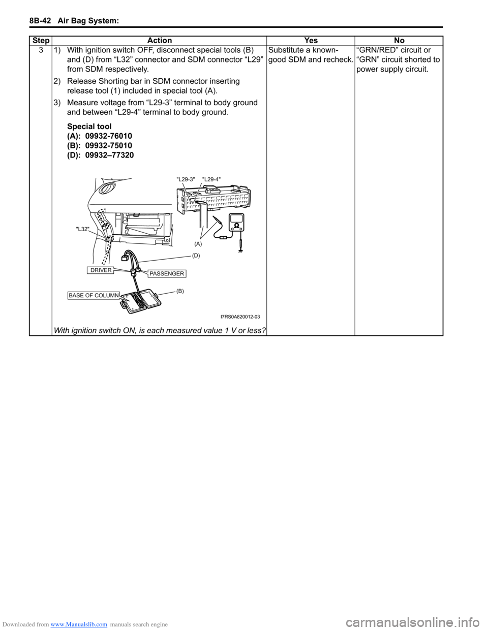
3 1) With ignition switch OFF, disconnect special tools (B) and (D) from “L32” connector and SDM connector “L29”
from SDM respectively.
2) Release Shorting bar in SDM connector inserting release tool (1) included in special tool (A).
3) Measure voltage from “L29-3” terminal to body ground and between “L29-4” terminal to body ground.
Special tool
(A): 09932-76010
(B): 09932-75010
(D): 09932–77320
With ignition switch ON, is each measured value 1 V or less? Substitute a known-
good SDM and recheck.
“GRN/RED” circuit or
“GRN” circuit shorted to
power supply circuit.
Step Action Yes No
(B) (D)
"L32"BASE OF COLUMN
DRIVERPASSENGER
(A)
"L29-4"
"L29-3"
I7RS0A820012-03