2005 SUZUKI JIMNY body
[x] Cancel search: bodyPage 4 of 687

Downloaded from www.Manualslib.com manuals search engine TABLE OF CONTENTS
GENERAL INFORMATIONGeneral Information0A0A
Maintenance and Lubrication0B
0B
HEATING AND AIR CONDITIONINGHeater and Ventilation1A
1A
Air Conditioning (Optional)1B
1B
STEERING, SUSPENSION, WHEELS AND
TIRESSteering, Suspension, Wheels and Tires3
3
Front Wheel Alignment3A
3A
Steering Gear Box (Manual Type) and Linkage3B
3B
Power Steering (P/S) System (if equipped)3B1
3B1
Steering Wheel and Column3C
3C
Front Suspension3D
3D
Rear Suspension3E
3E
Wheels and Tires3F
3F
DRIVE SHAFT AND PROPELLER SHAFT
Propeller Shafts4B
4B
BRAKE SYSTEMBrakes5
5
Antilock Brake System (ABS)5E
5E
ENGINEEngine General Information and Diagnosis6
6
Engine Mechanical (M13 Engine)6A1
6A1
Engine Cooling6B
6B
Engine Fuel6C
6C
Engine and Emission Control System6E
6E
Ignition System (Electronic Ignition System)6F
6F
Cranking System6G
6G
Charging System6H
6H
Exhaust System6K
6K
TRANSMISSION, CLUTCH AND
DIFFERENTIALManual Transmission7A
7A
Automatic Transmission (4 A/T)7B
7B
Clutch7C
7C
Transfer7D
7D
Front Differential7E
7E
Rear Differential7F
7F
ELECTRICAL SYSTEMBody Electrical System8
8
Immobilizer Control System (if equipped)8G
8G
BODY SERVICE9
9
RESTRAINT SYSTEMRestraint System10
10
Air Bag System10B
10B
Page 6 of 687

Downloaded from www.Manualslib.com manuals search engine GENERAL INFORMATION 0A-1
0A
6F2
6G
6H
6K
7A
7A1
7B1
7C1
7D
7E
7F
8A
8B
8C
8D
8E
9
10
10A
10B
SECTION 0A
GENERAL INFORMATION
CONTENTS
How to Use This Manual .................................0A-2
Precautions......................................................0A-3
Precaution for Vehicles Equipped with a
Supplemental Restraint (Air Bag) System ..... 0A-3
Diagnosis................................................... 0A-3
Servicing and handling .............................. 0A-4
General Precautions ..................................... 0A-7
Precautions For Catalytic Converter ........... 0A-10
Precautions For Electrical Circuit Service ... 0A-10
Electrical Circuit Inspection Procedure........ 0A-13
Open circuit check ................................... 0A-13
Short circuit check (wire harness to
ground) .................................................... 0A-15
Intermittent and Poor Connection ............... 0A-15
Precaution For Installing Mobile
Communication Equipment ......................... 0A-16Identification Information ............................. 0A-17
Body Number .............................................. 0A-17
Engine Identification Number ...................... 0A-17
Transmission Identification Number............ 0A-17
Warning, Caution and Information
Labels............................................................. 0A-18
Vehicle Lifting Points ................................... 0A-19
When Using Frame Contact Hoist .............. 0A-19
When Using Floor Jack ............................... 0A-20
Abbreviations May Be Used In This
Manual............................................................ 0A-21
Abbreviations .............................................. 0A-21
Fasteners Information .................................. 0A-24
Metric Fasteners ......................................... 0A-24
Fastener Strength Identification .................. 0A-24
Standard Tightening Torque ....................... 0A-24
Page 9 of 687

Downloaded from www.Manualslib.com manuals search engine 0A-4 GENERAL INFORMATION
Servicing and handling
WARNING:
Many of service procedures require disconnection of “Air
Bag” fuse and all air bag (inflator) module(s) from initia-
tor circuit to avoid an accidental deployment.
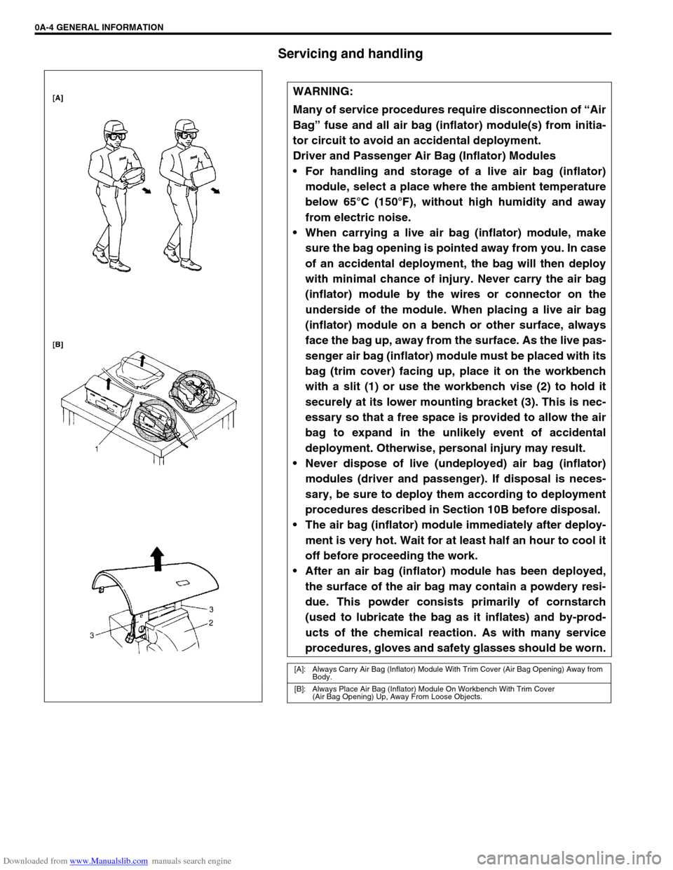
Driver and Passenger Air Bag (Inflator) Modules
For handling and storage of a live air bag (inflator)
module, select a place where the ambient temperature
below 65°C (150°F), without high humidity and away
from electric noise.
When carrying a live air bag (inflator) module, make
sure the bag opening is pointed away from you. In case
of an accidental deployment, the bag will then deploy
with minimal chance of injury. Never carry the air bag
(inflator) module by the wires or connector on the
underside of the module. When placing a live air bag
(inflator) module on a bench or other surface, always
face the bag up, away from the surface. As the live pas-
senger air bag (inflator) module must be placed with its
bag (trim cover) facing up, place it on the workbench
with a slit (1) or use the workbench vise (2) to hold it
securely at its lower mounting bracket (3). This is nec-
essary so that a free space is provided to allow the air
bag to expand in the unlikely event of accidental
deployment. Otherwise, personal injury may result.
Never dispose of live (undeployed) air bag (inflator)
modules (driver and passenger). If disposal is neces-
sary, be sure to deploy them according to deployment
procedures described in Section 10B before disposal.
The air bag (inflator) module immediately after deploy-
ment is very hot. Wait for at least half an hour to cool it
off before proceeding the work.
After an air bag (inflator) module has been deployed,
the surface of the air bag may contain a powdery resi-
due. This powder consists primarily of cornstarch
(used to lubricate the bag as it inflates) and by-prod-
ucts of the chemical reaction. As with many service
procedures, gloves and safety glasses should be worn.
[A]: Always Carry Air Bag (Inflator) Module With Trim Cover (Air Bag Opening) Away from
Body.
[B]: Always Place Air Bag (Inflator) Module On Workbench With Trim Cover
(Air Bag Opening) Up, Away From Loose Objects.
Page 16 of 687

Downloaded from www.Manualslib.com manuals search engine GENERAL INFORMATION 0A-11
When connecting connectors, also hold connectors and
push them together until they lock securely (a click is
heard).
When installing the wiring harness, fix it with clamps so
that no slack is left.
When installing vehicle parts, be careful so that the wir-
ing harness is not interfered with or caught by any other
part.
To avoid damage to the harness, protect its part which
may contact against a part forming a sharp angle by
winding tape or the like around it.
Be careful not to touch the electrical terminals of parts
which use microcomputers (e.g. electronic control unit
like as ECM, PCM, P/S controller, etc.). The static elec-
tricity from your body can damage these parts.
Page 19 of 687

Downloaded from www.Manualslib.com manuals search engine 0A-14 GENERAL INFORMATION
CONTINUITY CHECK
1) Measure resistance between connector terminals at both
ends of the circuit being checked (between A-1 and C-1 in
the figure).
If no continuity is indicated (infinity or over limit), that means
that the circuit is open between terminals A-1 and C-1.
2) Disconnect the connector included in the circuit (connector-B
in the figure) and measure resistance between terminals A-1
and B-1.
If no continuity is indicated, that means that the circuit is
open between terminals A-1 and B-1. If continuity is indi-
cated, there is an open circuit between terminals B-1 and C-
1 or an abnormality in connector-B.
VOLTAGE CHECK
If voltage is supplied to the circuit being checked, voltage check
can be used as circuit check.
1) With all connectors connected and voltage applied to the cir-
cuit being checked, measure voltage between each terminal
and body ground.
a) If measurements were taken as shown in the figure at the
left and results were as listed below, it means that the cir-
cuit is open between terminals B-1 and A-1.
Voltage Between
C-1 and body ground: Approx. 5V
B-1 and body ground: Approx. 5V
A-1 and body ground: 0V
b) Also, if measured values were as listed below, it means that
there is a resistance (abnormality) of such level that corre-
sponds to the voltage drop in the circuit between terminals
A-1 and B-1.
Voltage Between
C-1 and body ground: Approx. 5V
B-1 and body ground: Approx. 5V
A-1 and body ground: Approx. 3V (2V voltage drop)
Page 20 of 687

Downloaded from www.Manualslib.com manuals search engine GENERAL INFORMATION 0A-15
Short circuit check (wire harness to ground)
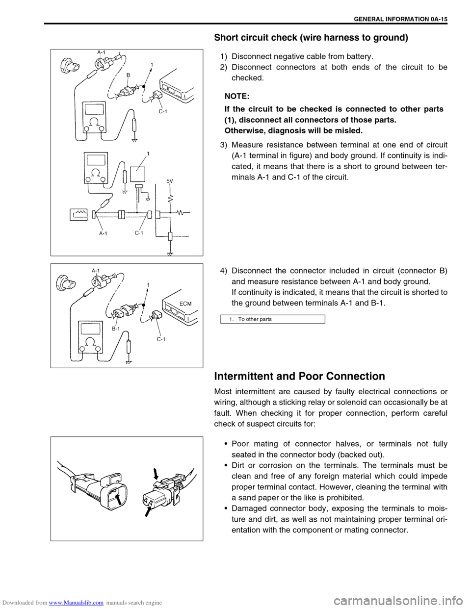
1) Disconnect negative cable from battery.
2) Disconnect connectors at both ends of the circuit to be
checked.
3) Measure resistance between terminal at one end of circuit
(A-1 terminal in figure) and body ground. If continuity is indi-
cated, it means that there is a short to ground between ter-
minals A-1 and C-1 of the circuit.
4) Disconnect the connector included in circuit (connector B)
and measure resistance between A-1 and body ground.
If continuity is indicated, it means that the circuit is shorted to
the ground between terminals A-1 and B-1.
Intermittent and Poor Connection
Most intermittent are caused by faulty electrical connections or
wiring, although a sticking relay or solenoid can occasionally be at
fault. When checking it for proper connection, perform careful
check of suspect circuits for:
Poor mating of connector halves, or terminals not fully
seated in the connector body (backed out).
Dirt or corrosion on the terminals. The terminals must be
clean and free of any foreign material which could impede
proper terminal contact. However, cleaning the terminal with
a sand paper or the like is prohibited.
Damaged connector body, exposing the terminals to mois-
ture and dirt, as well as not maintaining proper terminal ori-
entation with the component or mating connector. NOTE:
If the circuit to be checked is connected to other parts
(1), disconnect all connectors of those parts.
Otherwise, diagnosis will be misled.
1. To other parts
Page 22 of 687

Downloaded from www.Manualslib.com manuals search engine GENERAL INFORMATION 0A-17
Identification Information
Body Number
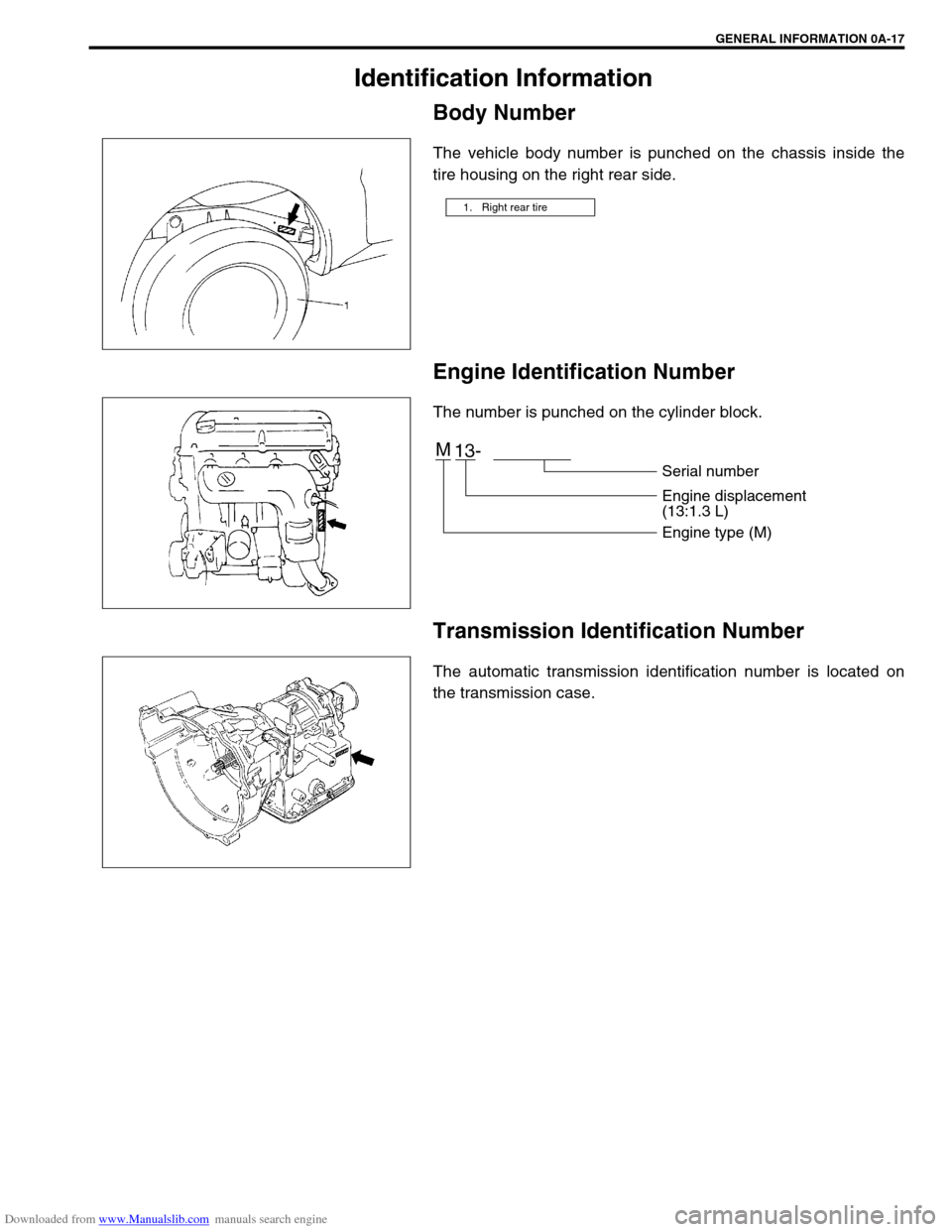
The vehicle body number is punched on the chassis inside the
tire housing on the right rear side.
Engine Identification Number
The number is punched on the cylinder block.
Transmission Identification Number
The automatic transmission identification number is located on
the transmission case.
1. Right rear tire
M
13-
Serial number
Engine displacement
(13:1.3 L)
Engine type (M)
Page 24 of 687

Downloaded from www.Manualslib.com manuals search engine GENERAL INFORMATION 0A-19
Vehicle Lifting Points
When Using Frame Contact Hoist
WARNING:
Before applying hoist to underbody, always take vehicle balance throughout service into consider-
ation. Vehicle balance on hoist may change depending on what part to be removed.
Before lifting up the vehicle, check to be sure that end of hoist arm is not in contact with brake pipe,
fuel pipe, bracket or any other part.
When using frame contact hoist, apply hoist as shown (right and left at the same position). Lift up
the vehicle till 4 tires are a little off the ground and make sure that the vehicle will not fall off by try-
ing to move vehicle body in both ways. Work can be started only after this confirmation.
Make absolutely sure to lock hoist after vehicle is hoisted up.
1. Front lifting point
2. Rear lifting point
3. Front