2005 SUZUKI JIMNY Eps
[x] Cancel search: EpsPage 26 of 687

Downloaded from www.Manualslib.com manuals search engine GENERAL INFORMATION 0A-21
Abbreviations May Be Used In This Manual
Abbreviations
AABC
ATDC
API
ATF
ALR
AC
A/T
A/C
ABDC
A/F
A-ELRAnti-lock Brake System
After Top Dead Center
American Petroleum Institute
Automatic Transmission Fluid
Automatic Locking Retractor
Alternating Current
Automatic Transmission
Air Conditioning
After Bottom Dead Center
Air Fuel Mixture Ratio
Automatic-Emergency
Locking RetractorEEBCM
ECM
ECT Sensor
EGR
EGRT Sensor
EFE Heater
ELR
EPS
EVAP
EVAP CanisterElectronic Brake Control Module,
ABS Control Module
Engine Control Module
Engine Coolant Temperature
Sensor (Water Temp. Sensor,
WTS)
Exhaust Gas Recirculation
EGR Temperature Sensor
(Recirculated Exhaust Gas Temp.
Sensor, REGTS)
Early Fuel Evaporation
Heater (Positive Temperature
Coefficient, PTC Heater)
Emergency Locking Retractor
Electronic Power Steering
Evaporative Emission
Evaporative Emission Canister
(Charcoal Canister) BB+
BTDC
BBDCBattery Positive Voltage
Before Top Dead Center
Before Bottom Dead Center
CCKT
CMP Sensor
CO
CPP Switch
CPU
CRSCircuit
Camshaft Position Sensor
(Crank Angle Sensor, CAS)
Carbon Monoxide
Clutch Pedal Position Switch
(Clutch Switch, Clutch Start
Switch)
Central Processing Unit
Child Restraint SystemF 4WD 4 Wheel Drive
GGEN
GNDGenerator
Ground
HHC
HO2SHydrocarbons
Heated Oxygen Sensor
DDC
DLC
DOHC
DOJ
DRL
DTCDirect Current
Data Link Connector
(Assembly Line Diag. Link, ALDL,
Serial Data Link, SDL)
Double Over Head Camshaft
Double Offset Joint
Daytime Running Light
Diagnostic Trouble Code
(Diagnostic Code)IIAC Valve
IAT Sensor
ICM
IG
ISC ActuatorIdle Air Control Valve (Idle Speed
Control Solenoid Valve, ISC
Solenoid Valve)
Intake Air Temperature Sensor
(Air temperature Sensor, ATS)
Immobilizer Control Module
Ignition
Idle Speed Control Actuator
(Motor)
Page 41 of 687
Downloaded from www.Manualslib.com manuals search engine 0B-10 MAINTENANCE AND LUBRICATION
REPLACEMENT
Replace air cleaner filter with new one according to steps 1), 2)
and 5), 6) of inspection procedure.
Fuel Lines and Connections
INSPECTION
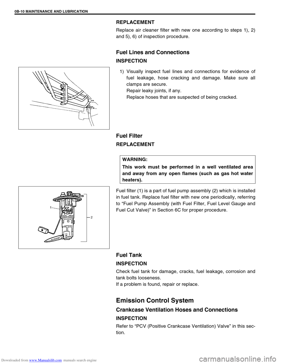
1) Visually inspect fuel lines and connections for evidence of
fuel leakage, hose cracking and damage. Make sure all
clamps are secure.
Repair leaky joints, if any.
Replace hoses that are suspected of being cracked.
Fuel Filter
REPLACEMENT
Fuel filter (1) is a part of fuel pump assembly (2) which is installed
in fuel tank. Replace fuel filter with new one periodically, referring
to “Fuel Pump Assembly (with Fuel Filter, Fuel Level Gauge and
Fuel Cut Valve)” in Section 6C for proper procedure.
Fuel Tank
INSPECTION
Check fuel tank for damage, cracks, fuel leakage, corrosion and
tank bolts looseness.
If a problem is found, repair or replace.
Emission Control System
Crankcase Ventilation Hoses and Connections
INSPECTION
Refer to “PCV (Positive Crankcase Ventilation) Valve” in this sec-
tion.
WARNING:
This work must be performed in a well ventilated area
and away from any open flames (such as gas hot water
heaters).
Page 46 of 687
Downloaded from www.Manualslib.com manuals search engine MAINTENANCE AND LUBRICATION 0B-15
REAR
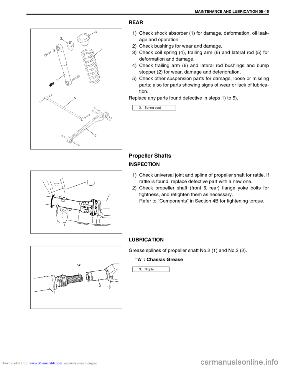
1) Check shock absorber (1) for damage, deformation, oil leak-
age and operation.
2) Check bushings for wear and damage.
3) Check coil spring (4), trailing arm (6) and lateral rod (5) for
deformation and damage.
4) Check trailing arm (6) and lateral rod bushings and bump
stopper (2) for wear, damage and deterioration.
5) Check other suspension parts for damage, loose or missing
parts; also for parts showing signs of wear or lack of lubrica-
tion.
Replace any parts found defective in steps 1) to 5).
Propeller Shafts
INSPECTION
1) Check universal joint and spline of propeller shaft for rattle. If
rattle is found, replace defective part with a new one.
2) Check propeller shaft (front & rear) flange yoke bolts for
tightness, and retighten them as necessary.
Refer to “Components” in Section 4B for tightening torque.
LUBRICATION
Grease splines of propeller shaft No.2 (1) and No.3 (2).
“A”: Chassis Grease
3. Spring seat
3. Nipple
Page 50 of 687
Downloaded from www.Manualslib.com manuals search engine MAINTENANCE AND LUBRICATION 0B-19
Power Steering (P/S) System (if equipped)
INSPECTION
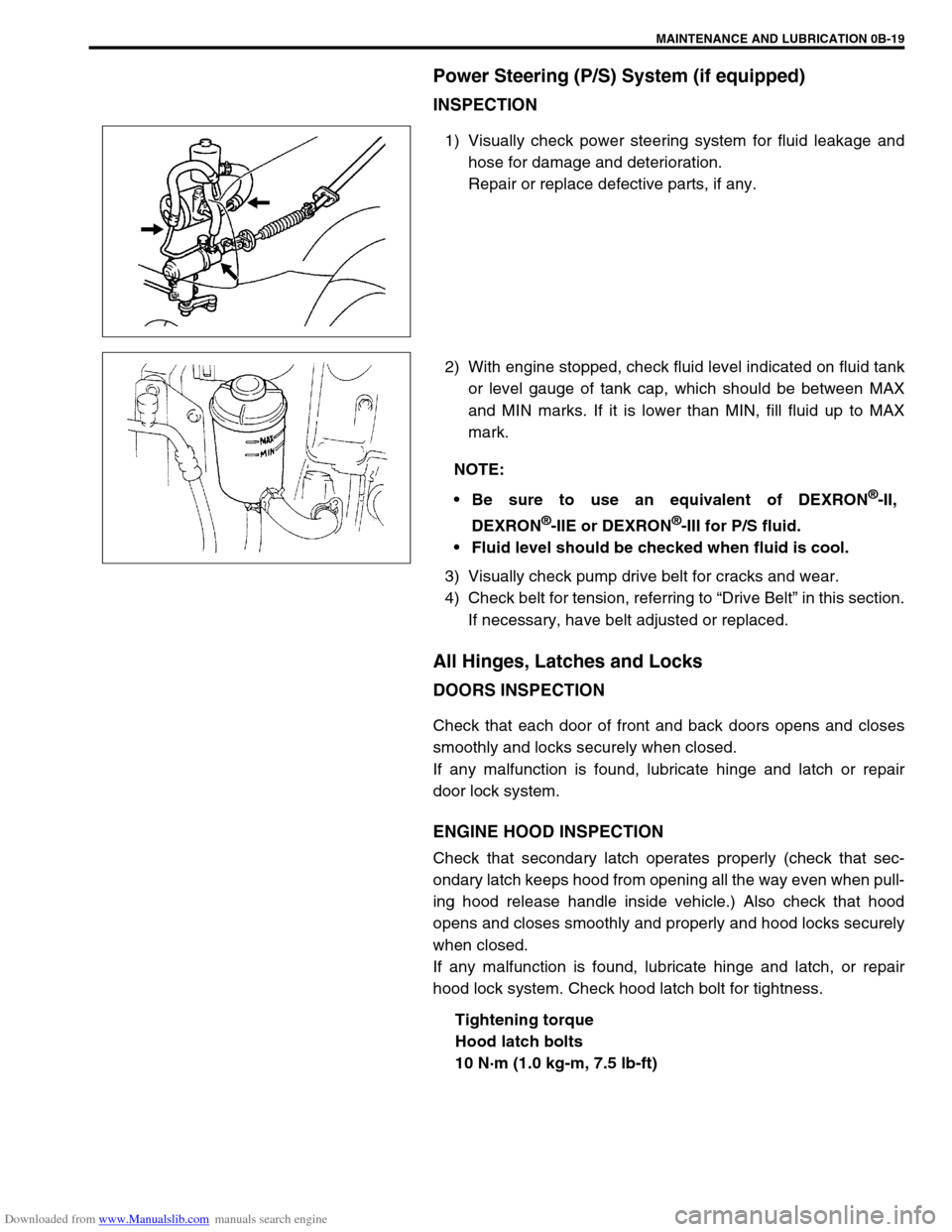
1) Visually check power steering system for fluid leakage and
hose for damage and deterioration.
Repair or replace defective parts, if any.
2) With engine stopped, check fluid level indicated on fluid tank
or level gauge of tank cap, which should be between MAX
and MIN marks. If it is lower than MIN, fill fluid up to MAX
mark.
3) Visually check pump drive belt for cracks and wear.
4) Check belt for tension, referring to “Drive Belt” in this section.
If necessary, have belt adjusted or replaced.
All Hinges, Latches and Locks
DOORS INSPECTION
Check that each door of front and back doors opens and closes
smoothly and locks securely when closed.
If any malfunction is found, lubricate hinge and latch or repair
door lock system.
ENGINE HOOD INSPECTION
Check that secondary latch operates properly (check that sec-
ondary latch keeps hood from opening all the way even when pull-
ing hood release handle inside vehicle.) Also check that hood
opens and closes smoothly and properly and hood locks securely
when closed.
If any malfunction is found, lubricate hinge and latch, or repair
hood lock system. Check hood latch bolt for tightness.
Tightening torque
Hood latch bolts
10 N·m (1.0 kg-m, 7.5 lb-ft)
NOTE:
Be sure to use an equivalent of DEXRON
®-II,
DEXRON
®-IIE or DEXRON®-III for P/S fluid.
Fluid level should be checked when fluid is cool.
Page 151 of 687

Downloaded from www.Manualslib.com manuals search engine 3B1-20 POWER STEERING (P/S) SYSTEM (If equipped)
Install pitman arm (1) to sector shaft (2) of P/S gear box (3)
with match marks “A” and “B” aligned as shown in figure and
torque to specification.
Tightening torque
Pitman arm mounting nut
(a) : 135 N·m (13.5 kg-m, 98.0 lb-ft)
Install lower shaft by the following steps.
1) Align flat part of steering gear box worm shaft (1) with bolt
hole in lower joint as shown. Then insert lower joint (2) onto
worm shaft.
2) Be sure that front wheels and steering wheel are in straight-
forward state and insert upper joint onto steering shaft.
3) Torque lower shaft joint bolt to specification.
Tightening torque
Steering shaft lower joint bolt
(a) : 25 N·m (2.5 kg-m, 18.0 lb-ft)
Fill engine coolant to radiator.
Bleed air in P/S circuit referring to “Air Bleeding Procedure”
in this section.
Page 187 of 687
Downloaded from www.Manualslib.com manuals search engine 3D-14 FRONT SUSPENSION
Shock Absorber and/or Coil Spring Check
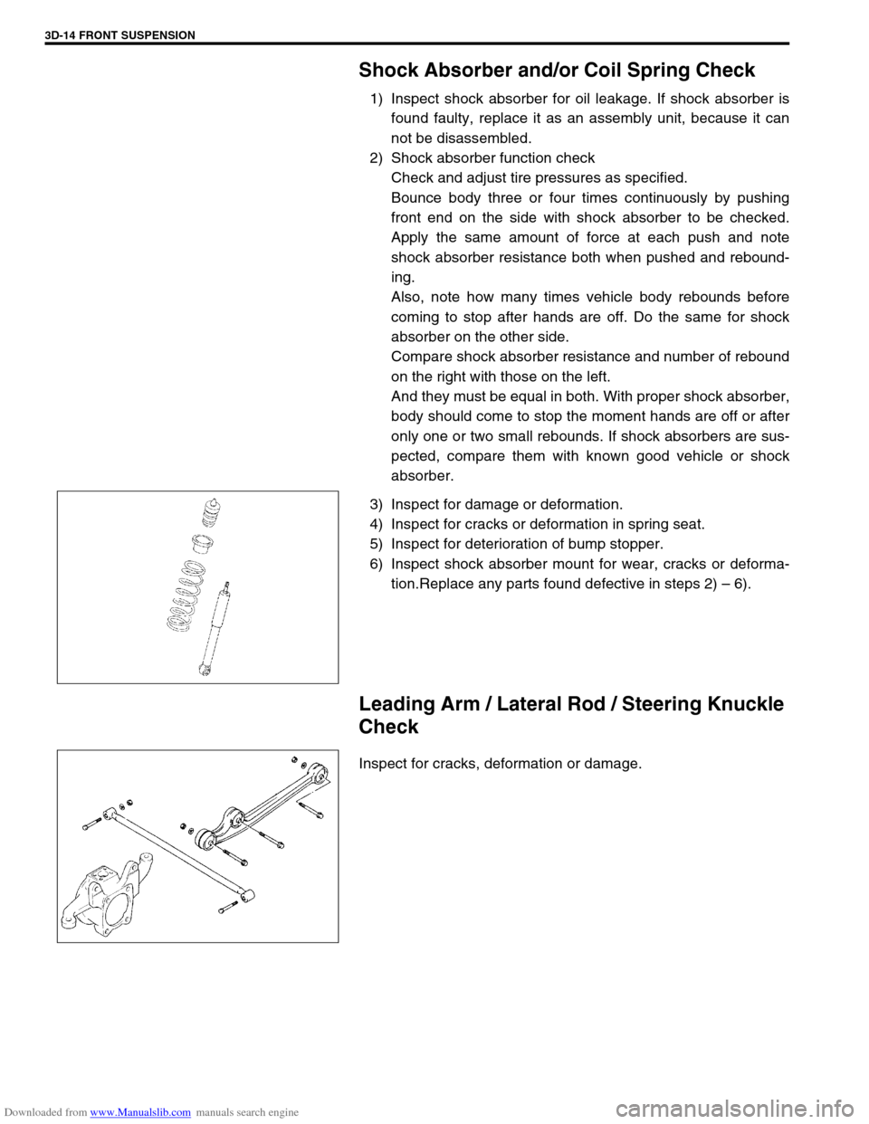
1) Inspect shock absorber for oil leakage. If shock absorber is
found faulty, replace it as an assembly unit, because it can
not be disassembled.
2) Shock absorber function check
Check and adjust tire pressures as specified.
Bounce body three or four times continuously by pushing
front end on the side with shock absorber to be checked.
Apply the same amount of force at each push and note
shock absorber resistance both when pushed and rebound-
ing.
Also, note how many times vehicle body rebounds before
coming to stop after hands are off. Do the same for shock
absorber on the other side.
Compare shock absorber resistance and number of rebound
on the right with those on the left.
And they must be equal in both. With proper shock absorber,
body should come to stop the moment hands are off or after
only one or two small rebounds. If shock absorbers are sus-
pected, compare them with known good vehicle or shock
absorber.
3) Inspect for damage or deformation.
4) Inspect for cracks or deformation in spring seat.
5) Inspect for deterioration of bump stopper.
6) Inspect shock absorber mount for wear, cracks or deforma-
tion.Replace any parts found defective in steps 2) – 6).
Leading Arm / Lateral Rod / Steering Knuckle
Check
Inspect for cracks, deformation or damage.
Page 277 of 687
Downloaded from www.Manualslib.com manuals search engine 5-16 BRAKES
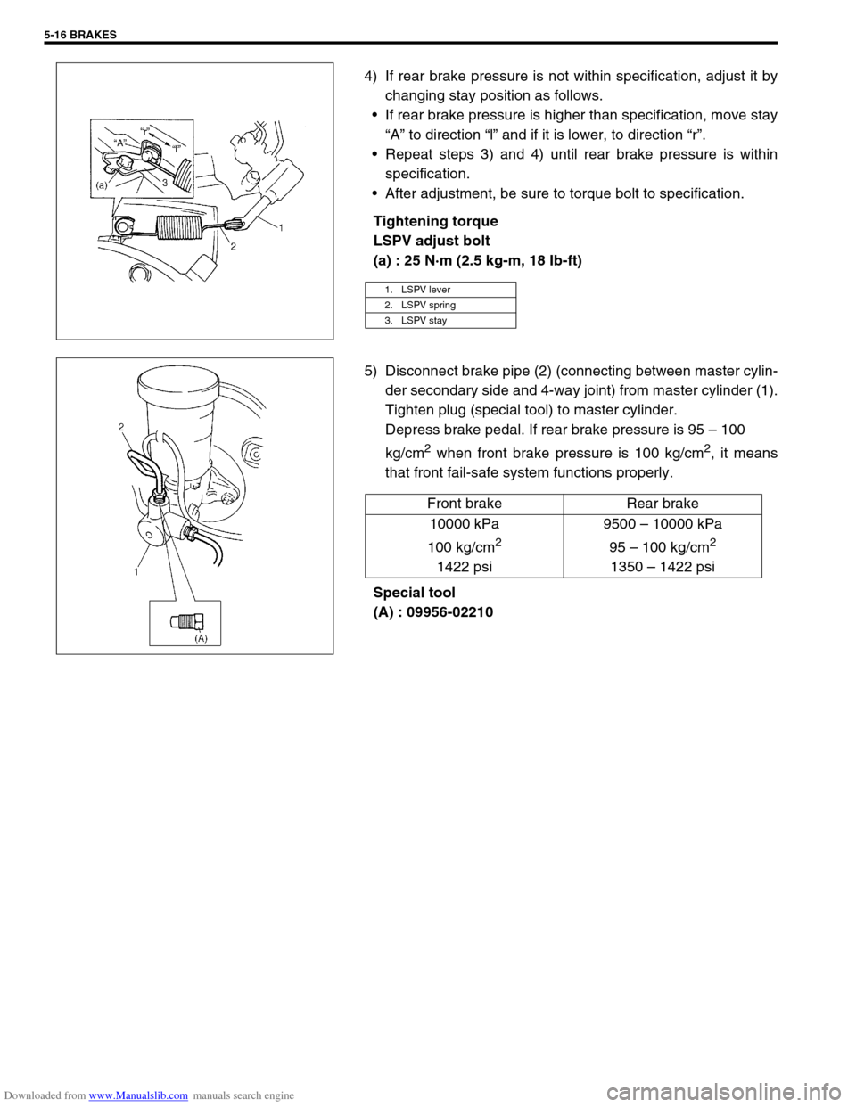
4) If rear brake pressure is not within specification, adjust it by
changing stay position as follows.
If rear brake pressure is higher than specification, move stay
“A” to direction “l” and if it is lower, to direction “r”.
Repeat steps 3) and 4) until rear brake pressure is within
specification.
After adjustment, be sure to torque bolt to specification.
Tightening torque
LSPV adjust bolt
(a) : 25 N·m (2.5 kg-m, 18 Ib-ft)
5) Disconnect brake pipe (2) (connecting between master cylin-
der secondary side and 4-way joint) from master cylinder (1).
Tighten plug (special tool) to master cylinder.
Depress brake pedal. If rear brake pressure is 95 – 100
kg/cm
2 when front brake pressure is 100 kg/cm2, it means
that front fail-safe system functions properly.
Special tool
(A) : 09956-02210
1. LSPV lever
2. LSPV spring
3. LSPV stay
Front brake Rear brake
10000 kPa
100 kg/cm
2
1422 psi9500 – 10000 kPa
95 – 100 kg/cm
2
1350 – 1422 psi
Page 331 of 687
Downloaded from www.Manualslib.com manuals search engine 5E-14 ANTILOCK BRAKE SYSTEM (ABS)
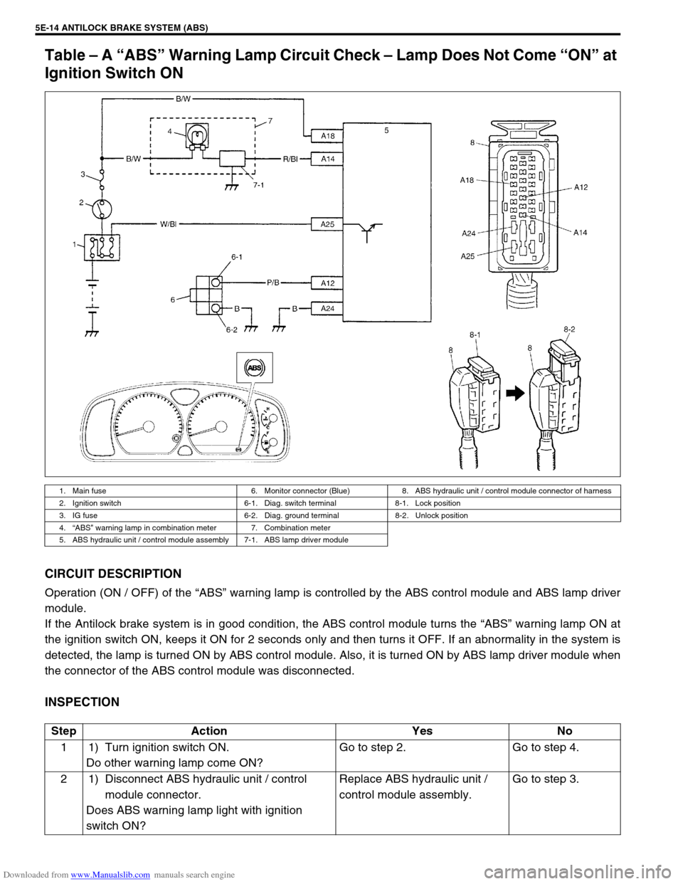
Table – A “ABS” Warning Lamp Circuit Check – Lamp Does Not Come “ON” at
Ignition Switch ON
CIRCUIT DESCRIPTION
Operation (ON / OFF) of the “ABS” warning lamp is controlled by the ABS control module and ABS lamp driver
module.
If the Antilock brake system is in good condition, the ABS control module turns the “ABS” warning lamp ON at
the ignition switch ON, keeps it ON for 2 seconds only and then turns it OFF. If an abnormality in the system is
detected, the lamp is turned ON by ABS control module. Also, it is turned ON by ABS lamp driver module when
the connector of the ABS control module was disconnected.
INSPECTION
1. Main fuse 6. Monitor connector (Blue) 8. ABS hydraulic unit / control module connector of harness
2. Ignition switch 6-1. Diag. switch terminal 8-1. Lock position
3. IG fuse 6-2. Diag. ground terminal 8-2. Unlock position
4.“ABS” warning lamp in combination meter 7. Combination meter
5. ABS hydraulic unit / control module assembly 7-1. ABS lamp driver module
Step Action Yes No
1 1) Turn ignition switch ON.
Do other warning lamp come ON?Go to step 2. Go to step 4.
2 1) Disconnect ABS hydraulic unit / control
module connector.
Does ABS warning lamp light with ignition
switch ON?Replace ABS hydraulic unit /
control module assembly.Go to step 3.