2005 SUZUKI JIMNY engine light
[x] Cancel search: engine lightPage 618 of 687

Downloaded from www.Manualslib.com manuals search engine ENGINE AND EMISSION CONTROL SYSTEM 6E-13
ECM TERMINAL ARRANGEMENT TABLE
For TYPE A (See NOTE)
CONNEC-
TORTERMINAL WIRE COLOR CIRCUITCONNEC-
TORTERMINAL WIRE COLOR CIRCUIT
E191 B Ground for ECM
E187 W Backup power source
2 B/R Ground for drive circuit
8R/GImmobilizer indicator lamp
(if equipped)
3 B/R Ground for drive circuitDuty output terminal (vehicle without
immobilizer indicator lamp)
4 Bl/G Canister purge valve 9––
5 Bl/OrPower steering pressure switch
(if equipped)10 Bl Main relay
6 G/Y IAC valve 11 Br Tachometer
7 P/B Heater of HO2S-1 (if equipped) 12 Y/B Data link connector (5 V)
8 W/B No.4 fuel injector 13 WHeated oxygen sensor-2
(if equipped)
9 R/W No.1 fuel injector 14 W/BIDiagnosis switch terminal
(vehicle without immobilizer indicator
lamp)
10 B/Bl Ground for sensor circuit 15 PTest switch terminal
(vehicle without immobilizer indicator
lamp)
11 W CMP sensor 16 G/W A/C SW signal (if equipped)
12––17 R/Y Lighting switch
13R
R/BlHeated oxygen sensor-1
(if equipped)
CO adjusting resistor (w/o HO2S)18 P/B A/C condenser fan relay (if equipped)
14 G/B ECT sensor 19 W/G Fuel pump relay
15 Lg/B IAT sensor 20 B/Bl Ground for sensor
16 Lg TP sensor 21 B/RThrottle opening signal output for A/T
(A/T)
17 Gr/BIEGR valve (stepper motor coil 3, if
equipped)22 Y/RFuel level gauge (vehicle with immo-
bilizer indicator lamp)
18 GrEGR valve (stepper motor coil 1, if
equipped)23––
19 Br/BIG coil assembly for No.2 and 3 spark
plugs24 Bl/Y Heater blower switch
20 Br/WIG coil assembly for No.1 and 4 spark
plugs
21 R/G No.2 fuel injector
E171––
22 Lg/R Power supply for sensor 2 R R-range signal (A/T)
23 G/R CKP sensor 3––
24––4––
25 W Knock sensor 5 B/Or Overdrive cut signal (A/T)
26 G MAP sensor 6 G/Y D-range idle-up signal (A/T)
27 W/R A/C evaporator temp. sensor 7 G/W Stop lamp switch
28 Gr/BEGR valve (stepper motor coil 4, if
equipped)8––
29 Gr/REGR valve (stepper motor coil 2, if
equipped)9 B/W Ignition switch
30––10––
31 W/G No.3 fuel injector 11 Y Vehicle speed sensor
12 G ABS signal (if equipped)
E181 P A/C compressor clutch (if equipped) 13B/Y (M/T)
B/R (A/T)Engine start signal
2 V/Y Malfunction indicator lamp 14––
3 P/G Data link connector (12 V) 15––
4 R/BI Heater of HO2S-2 (if equipped) 16 R/W Rear defogger switch (if equipped)
5 Bl/B Power source 17 G/RA/T failure signal (A/T) (vehicle with
immobilizer indicator lamp)
6 Bl/B Power source
NOTE:
See NOTE in “ECM INPUT / OUTPUT CIRCUIT DIAGRAM” for applicable model.
Page 619 of 687

Downloaded from www.Manualslib.com manuals search engine 6E-14 ENGINE AND EMISSION CONTROL SYSTEM
For TYPE B (See NOTE)
CONNEC-
TORTERMINAL WIRE COLOR CIRCUITCONNEC-
TORTERMINAL WIRE COLOR CIRCUIT
E191 B Ground for ECM
E187 W Backup power source
2 B/R Ground for drive circuit
8R/GImmobilizer indicator lamp
(if equipped)
3 B/R Ground for drive circuitDuty output terminal (vehicle without
immobilizer indicator lamp)
4 Bl/G Canister purge valve 9––
5 Bl/OrPower steering pressure switch
(if equipped)10 Bl Main relay
6 G/Y IAC valve 11 B/W Ignition switch
7 P/B Heater of HO2S-1 (if equipped) 12 R/W Rear defogger switch
8 W/B No.4 fuel injector 13––
9 R/W No.1 fuel injector 14 W/BIDiagnosis switch terminal
(vehicle without immobilizer indicator
lamp)
10 B/Bl Ground for sensor circuit 15 PTest switch terminal
(vehicle without immobilizer indicator
lamp)
11 W CMP sensor 16 G/W A/C SW signal (if equipped)
12––17 R/Y Lighting switch
13R
R/BlHeated oxygen sensor-1
(if equipped)
CO adjusting resistor (w/o HO2S)18 P/B A/C condenser fan relay (if equipped)
14 G/B ECT sensor 19 W/G Fuel pump relay
15 Lg/B IAT sensor 20B/Y (M/T)
B/R (A/T)Engine start signal
16 Lg TP sensor 21 G/W Stop lamp switch
17 Gr/BIEGR valve (stepper motor coil 3, if
equipped)22 Y Vehicle speed sensor
18 GrEGR valve (stepper motor coil 1, if
equipped)23––
19 Br/BIG coil assembly for No.2 and 3 spark
plugs24––
20 Br/WIG coil assembly for No.1 and 4 spark
plugs
21 R/G No.2 fuel injector
E171 W/R A/C evaporator temp. sensor
22 Lg/R Power supply for sensor 2 R R-range signal (A/T)
23 G/R CKP sensor 3––
24––4––
25 W Knock sensor 5 B/Or Overdrive cut signal (A/T)
26 G MAP sensor 6 G/Y D-range idle-up signal (A/T)
27––7 Y/B Data link connector
28 Gr/BEGR valve (stepper motor coil 4, if
equipped)8––
29 Gr/REGR valve (stepper motor coil 2, if
equipped)9 V/Y Malfunction indicator lamp
30––10––
31 W/G No.3 fuel injector 11 P/G Data link connector (12 V)
12 G ABS signal (if equipped)
E181 P A/C compressor clutch (if equipped) 13 Bl/Y Heater blower switch
2––14 B/Bl Ground for sensor
3––15 B/R Throttle opening sensor
4 R/BI Heater of HO2S-2 (if equipped) 16 Br Tachometer
5 Bl/B Power source 17––
6 Bl/B Power source
NOTE:
See NOTE in “ECM INPUT / OUTPUT CIRCUIT DIAGRAM” for applicable model.
Page 620 of 687

Downloaded from www.Manualslib.com manuals search engine ENGINE AND EMISSION CONTROL SYSTEM 6E-15
On-Vehicle Service
Accelerator cable adjustment
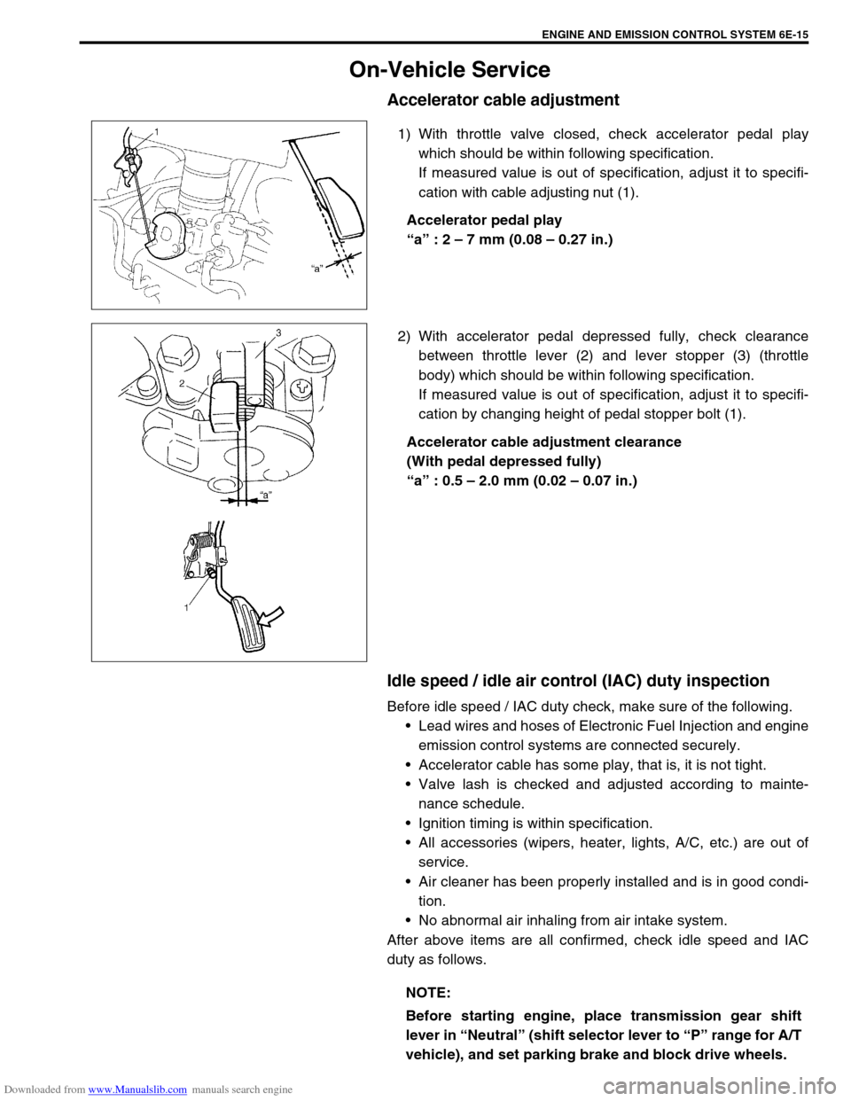
1) With throttle valve closed, check accelerator pedal play
which should be within following specification.
If measured value is out of specification, adjust it to specifi-
cation with cable adjusting nut (1).
Accelerator pedal play
“a” : 2 – 7 mm (0.08 – 0.27 in.)
2) With accelerator pedal depressed fully, check clearance
between throttle lever (2) and lever stopper (3) (throttle
body) which should be within following specification.
If measured value is out of specification, adjust it to specifi-
cation by changing height of pedal stopper bolt (1).
Accelerator cable adjustment clearance
(With pedal depressed fully)
“a” : 0.5 – 2.0 mm (0.02 – 0.07 in.)
Idle speed / idle air control (IAC) duty inspection
Before idle speed / IAC duty check, make sure of the following.
Lead wires and hoses of Electronic Fuel Injection and engine
emission control systems are connected securely.
Accelerator cable has some play, that is, it is not tight.
Valve lash is checked and adjusted according to mainte-
nance schedule.
Ignition timing is within specification.
All accessories (wipers, heater, lights, A/C, etc.) are out of
service.
Air cleaner has been properly installed and is in good condi-
tion.
No abnormal air inhaling from air intake system.
After above items are all confirmed, check idle speed and IAC
duty as follows.
NOTE:
Before starting engine, place transmission gear shift
lever in “Neutral” (shift selector lever to “P” range for A/T
vehicle), and set parking brake and block drive wheels.
Page 658 of 687

Downloaded from www.Manualslib.com manuals search engine IGNITION SYSTEM (ELECTRONIC IGNITION SYSTEM 6F-9
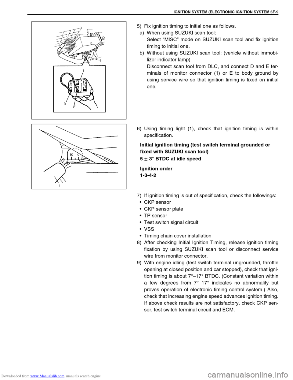
5) Fix ignition timing to initial one as follows.
a) When using SUZUKI scan tool:
Select “MISC” mode on SUZUKI scan tool and fix ignition
timing to initial one.
b) Without using SUZUKI scan tool: (vehicle without immobi-
lizer indicator lamp)
Disconnect scan tool from DLC, and connect D and E ter-
minals of monitor connector (1) or E to body ground by
using service wire so that ignition timing is fixed on initial
one.
6) Using timing light (1), check that ignition timing is within
specification.
Initial ignition timing (test switch terminal grounded or
fixed with SUZUKI scan tool)
5
± 3° BTDC at idle speed
Ignition order
1-3-4-2
7) If ignition timing is out of specification, check the followings:
CKP sensor
CKP sensor plate
TP sensor
Test switch signal circuit
VSS
Timing chain cover installation
8) After checking Initial Ignition Timing, release ignition timing
fixation by using SUZUKI scan tool or disconnect service
wire from monitor connector.
9) With engine idling (test switch terminal ungrounded, throttle
opening at closed position and car stopped), check that igni-
tion timing is about 7°–17° BTDC. (Constant variation within
a few degrees from 7°–17° indicates no abnormality but
proves operation of electronic timing control system.) Also,
check that increasing engine speed advances ignition timing.
If above check results are not satisfactory, check CKP sen-
sor, test switch terminal circuit and ECM.
Page 670 of 687

Downloaded from www.Manualslib.com manuals search engine CHARGING SYSTEM 6H-3
BUILT-IN INDICATOR (IF EQUIPPED)
The battery has a built-in temperature compensated indicator in
the top of the battery. This indicator is to be used with the follow-
ing diagnostic procedure. When checking the indicator, make
sure that the battery has a clean top. A light may be needed in
some poorly-lit areas.
Three types of indication which is available under normal opera-
tion are as follows.
Green Dot
Battery is sufficiently charged for testing.
Dark
Battery must be charged before testing.
If there is a cranking complaint, battery should be tested as
described in Diagnosis section. Charging and electrical sys-
tems should also be checked at this time.
Clear or Light Yellow
This means that fluid level is below the bottom of hydrome-
ter. Its possible cause is excessive or prolonged charging, a
broken case, excessive tipping or normal battery deteriora-
tion.
When the battery is found in such condition, it is possible
that high charging voltage is caused by the faulty charging
system and therefore, charging and electrical systems need
to be checked. If there is a trouble in cranking and its cause
lies in the battery, it should be replaced.
CARE OF BATTERY
1) The battery is a very reliable component, but needs periodi-
cal attentions.
Keep the battery carrier clean.
Prevent rust formation on the terminal posts.
Keep the electrolyte up to the upper level uniformly in all
cells. WARNING:
Never expose battery to open flame or electric spark
because of battery generate gas which is flammable
and explosive.
Do not allow battery fluid to contact eyes, skin, fabrics,
or painted surfaces as fluid is a corrosive acid. Flush
any contacted area with water immediately and thor-
oughly.
Batteries should always be kept out of reach of chil-
dren.
Page 672 of 687

Downloaded from www.Manualslib.com manuals search engine CHARGING SYSTEM 6H-5
1. Generator with regulator assembly 3. Stator coil 5. Field coil (rotor coil) 7. Main switch
2. I.C. regulator 4. Diode 6. Charge indicator light 8. Battery
1. Pulley 5. Stator core 9. Front housing IG: Ignition terminal
2. Pulley nut 6. Field coil 10. Rear housing L: Lamp terminal
3. Rotor fan 7. Regulator B: Generator output (Battery terminal)
4. Stator coil 8. Brush E: Ground
Page 674 of 687

Downloaded from www.Manualslib.com manuals search engine CHARGING SYSTEM 6H-7
How to use the temperature-corrected state-of-charge
graph
Suppose your S.G. reading is 1.28 and the battery temperature is
–5 °C (23 °F). Locate the intersection of the –5 °C line and the
1.28 S.G. line.
The intersection is within the “A” zone (shaded area in the graph)
and that means CHARGED STATE.
To know how much the battery is charged, draw a line parallel to
the zone demarcation line and extend it to the right till it meets
with the percentage scale. In the present example, the line meets
at about 85% point on the percentage scale. Therefore, the bat-
tery is charged up to the 85% level.
Generator
Trouble in charging system will show up as one or more of follow-
ing conditions:
1) Faulty indicator lamp operation.
2) An undercharged battery as evidenced by slow cranking or
indicator dark.
3) An overcharged battery as evidenced by excessive spewing
of electrolyte from vents.
Noise from generator may be caused by a loose drive pulley,
loose mounting bolts, worn or dirty bearings, defective diode, or
defective stator.
FAULTY INDICATOR LAMP OPERATION
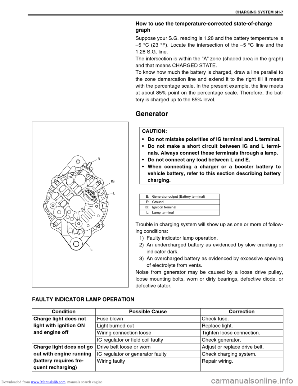
CAUTION:
Do not mistake polarities of IG terminal and L terminal.
Do not make a short circuit between IG and L termi-
nals. Always connect these terminals through a lamp.
Do not connect any load between L and E.
When connecting a charger or a booster battery to
vehicle battery, refer to this section describing battery
charging.
B: Generator output (Battery terminal)
E: Ground
IG: Ignition terminal
L: Lamp terminal
Condition Possible Cause Correction
Charge light does not
light with ignition ON
and engine offFuse blown Check fuse.
Light burned out Replace light.
Wiring connection loose Tighten loose connection.
IC regulator or field coil faulty Check generator.
Charge light does not go
out with engine running
(battery requires fre-
quent recharging)Drive belt loose or worn Adjust or replace drive belt.
IC regulator or generator faulty Check charging system.
Wiring faulty Repair wiring.
Page 676 of 687

Downloaded from www.Manualslib.com manuals search engine CHARGING SYSTEM 6H-9
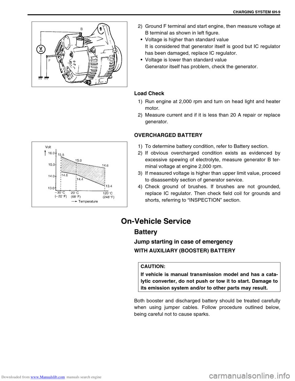
2) Ground F terminal and start engine, then measure voltage at
B terminal as shown in left figure.
Voltage is higher than standard value
It is considered that generator itself is good but IC regulator
has been damaged, replace IC regulator.
Voltage is lower than standard value
Generator itself has problem, check the generator.
Load Check
1) Run engine at 2,000 rpm and turn on head light and heater
motor.
2) Measure current and if it is less than 20 A repair or replace
generator.
OVERCHARGED BATTERY
1) To determine battery condition, refer to Battery section.
2) If obvious overcharged condition exists as evidenced by
excessive spewing of electrolyte, measure generator B ter-
minal voltage at engine 2,000 rpm.
3) If measured voltage is higher than upper limit value, proceed
to disassembly section of generator service.
4) Check ground of brushes. If brushes are not grounded,
replace IC regulator. Then check field coil for grounds and
shorts, referring to “INSPECTION” section.
On-Vehicle Service
Battery
Jump starting in case of emergency
WITH AUXILIARY (BOOSTER) BATTERY
Both booster and discharged battery should be treated carefully
when using jumper cables. Follow procedure outlined below,
being careful not to cause sparks.
CAUTION:
If vehicle is manual transmission model and has a cata-
lytic converter, do not push or tow it to start. Damage to
its emission system and/or to other parts may result.