Page 94 of 687
Downloaded from www.Manualslib.com manuals search engine AIR CONDITIONING (OPTIONAL) 1B-33
Condenser Cooling Fan Assembly
ASSEMBLY
INSPECTION
1) Check continuity between each two terminals about the con-
denser cooling fan motor (1).
If check results are no continuity, replace condenser cooling
fan motor.
2) Connect battery to condenser cooling fan motor as shown in
figure, then check that the condenser cooling fan motor
operates smoothly.
Reference current of condenser cooling fan motor
approximately 7.5 A at 12 V
REMOVAL
1) Remove front bumper.
2) Disconnect condenser cooling fan motor connector (1).
3) Remove radiator mounting bolts.
4) Remove condenser cooling fan assembly (2) from con-
denser (3).
INSTALLATION
Reverse removal procedure for installation.CAUTION:
Be careful not to damage condenser fins. If condenser fin
is bent, straighten condenser fin by using flat head
screwdriver or pair of pliers.
Page 95 of 687
Downloaded from www.Manualslib.com manuals search engine 1B-34 AIR CONDITIONING (OPTIONAL)
Cooling Unit (Evaporator)
REMOVAL
1) Disconnect negative (–) cable at battery.
2) Recover refrigerant from A/C system by referring to “Recov-
ery” in this section. CAUTION:
Be careful not to damage A/C evaporator fins. If A/C evaporator fin is bent, straighten A/C evaporator
fin by using flat head screwdriver or pair of pliers.
1. A/C evaporator 3. Expansion valve 5. Packing 7. O-ring
2. A/C evaporator thermistor
(A/C evaporator temperature sensor)4. Evaporator case 6. Air inlet door 8. Door link
NOTE:
The amount of removed compressor oil must be mea-
sured for replenishing compressor oil.
Page 96 of 687
Downloaded from www.Manualslib.com manuals search engine AIR CONDITIONING (OPTIONAL) 1B-35
3) Drain engine coolant and disconnect heater hoses (1) from
heater unit.
4) Disable air bag system referring to “Disabling Air Bag Sys-
tem” in Section 10B (if equipped).
5) Remove attaching bolt (1).
6) Disconnect suction hose (2) and receiver / dryer outlet pipe
(3) from expansion valve (4).
7) Remove instrument panel referring to “Instrument Panel” in
Section 9.
8) Remove cooling unit (1) with heater unit (2) from vehicle
body.
9) Remove cooling unit (1) from heater unit (2).
INSPECTION
Check the following.
Check clog of A/C evaporator fins.
If any clogs are found, A/C evaporator fins should be
washed with water, and should be dried with compressed
air.
Check A/C evaporator fins for leakage and breakage.
If any defects are found, repair or replace A/C evaporator.
Check A/C evaporator fittings for leakage.
If any defects are found, repair or replace A/C evaporator.
Page 97 of 687
Downloaded from www.Manualslib.com manuals search engine 1B-36 AIR CONDITIONING (OPTIONAL)
INSTALLATION
Reverse removal procedure to install cooling unit, and then noting
the following instructions.
If A/C evaporator thermistor removed, its should be rein-
stalled in original position.
Install uniformly the packing (1) to installation hole.
Replenish specified amount of compressor oil to compressor
suction side by referring to “Replenishing Compressor Oil” in
this section.
Evacuate and charge refrigerant by referring to “Evacuating”
and “Charging” in this section.
Adjust mode control cable, temperature control cable and
fresh air control cable by referring to “Heater Control Lever
Assembly” in Section 1A.
Enable air bag system referring to “Enable Air Bag System”
in Section 10B. (if equipped)
Fill engine coolant to radiator, referring to “Cooling System
Flush and Refill” in Section 6B.
Page 98 of 687
Downloaded from www.Manualslib.com manuals search engine AIR CONDITIONING (OPTIONAL) 1B-37
A/C Evaporator Thermistor (A/C Evaporator
Temperature Sensor)
INSPECTION
Check resistance between terminals for A/C evaporator ther-
mistor (1).
If check results are as not specified, replace thermistor.
A/C evaporator temperature sensor resistance
Expansion Valve
INSPECTION
Refer to “Performance Diagnosis” in this section.
REMOVAL
1) Disconnect negative (–) cable at battery.
2) Recover refrigerant from A/C system by referring to
“Recover” in this section.
3) Remove attaching bolt (1).
4) Remove suction hose (2) and receiver dryer outlet pipe (3)
from expansion valve (4).
5) Remove expansion valve (4).Sensor Temperature (°C (°F)) Resistance (k
Ω)
0 (32) 6.4 – 7.0
25 (77) 1.8 – 2.2
NOTE:
When A/C evaporator thermistor (1) removed, its should
be reinstalled in original position.
NOTE:
The amount of removed compressor oil must be mea-
sured for replenishing compressor oil.
Page 99 of 687

Downloaded from www.Manualslib.com manuals search engine 1B-38 AIR CONDITIONING (OPTIONAL)
INSTALLATION
Reverse removal procedure for installation, and then note the fol-
lowing instructions.
Replenish specified amount of compressor oil to compressor
suction side by referring to “Replenishing Compressor Oil” in
this section.
Evacuate and charge refrigerant by referring to “Evacuation”
and “Charging” in this section.
Dual Pressure Switch
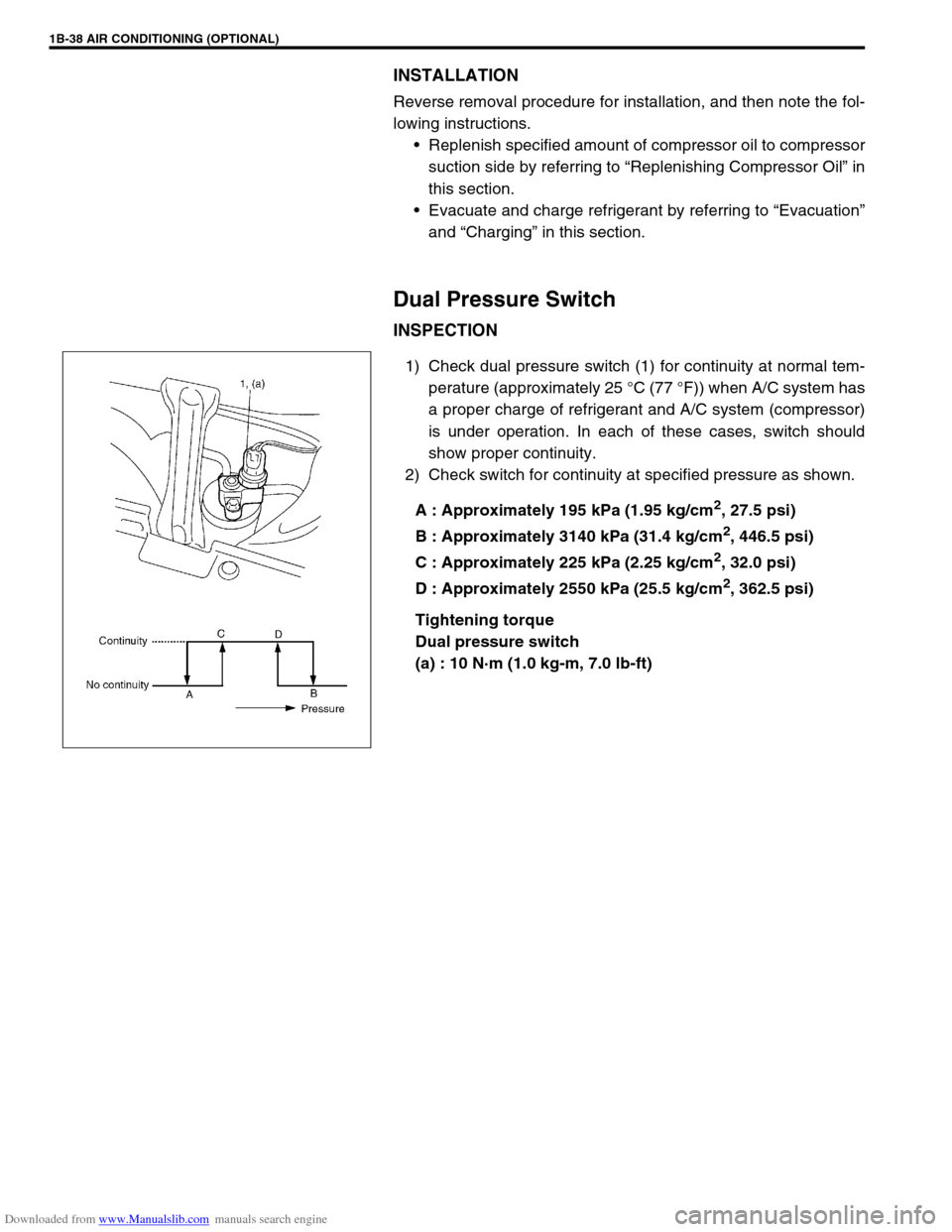
INSPECTION
1) Check dual pressure switch (1) for continuity at normal tem-
perature (approximately 25 °C (77 °F)) when A/C system has
a proper charge of refrigerant and A/C system (compressor)
is under operation. In each of these cases, switch should
show proper continuity.
2) Check switch for continuity at specified pressure as shown.
A : Approximately 195 kPa (1.95 kg/cm
2, 27.5 psi)
B : Approximately 3140 kPa (31.4 kg/cm
2, 446.5 psi)
C : Approximately 225 kPa (2.25 kg/cm
2, 32.0 psi)
D : Approximately 2550 kPa (25.5 kg/cm
2, 362.5 psi)
Tightening torque
Dual pressure switch
(a) : 10 N·m (1.0 kg-m, 7.0 lb-ft)
Page 100 of 687

Downloaded from www.Manualslib.com manuals search engine AIR CONDITIONING (OPTIONAL) 1B-39
A/C Switch
REMOVAL AND INSTALLATION
Refer to “Heater Control Lever Assembly” in Section 1A.
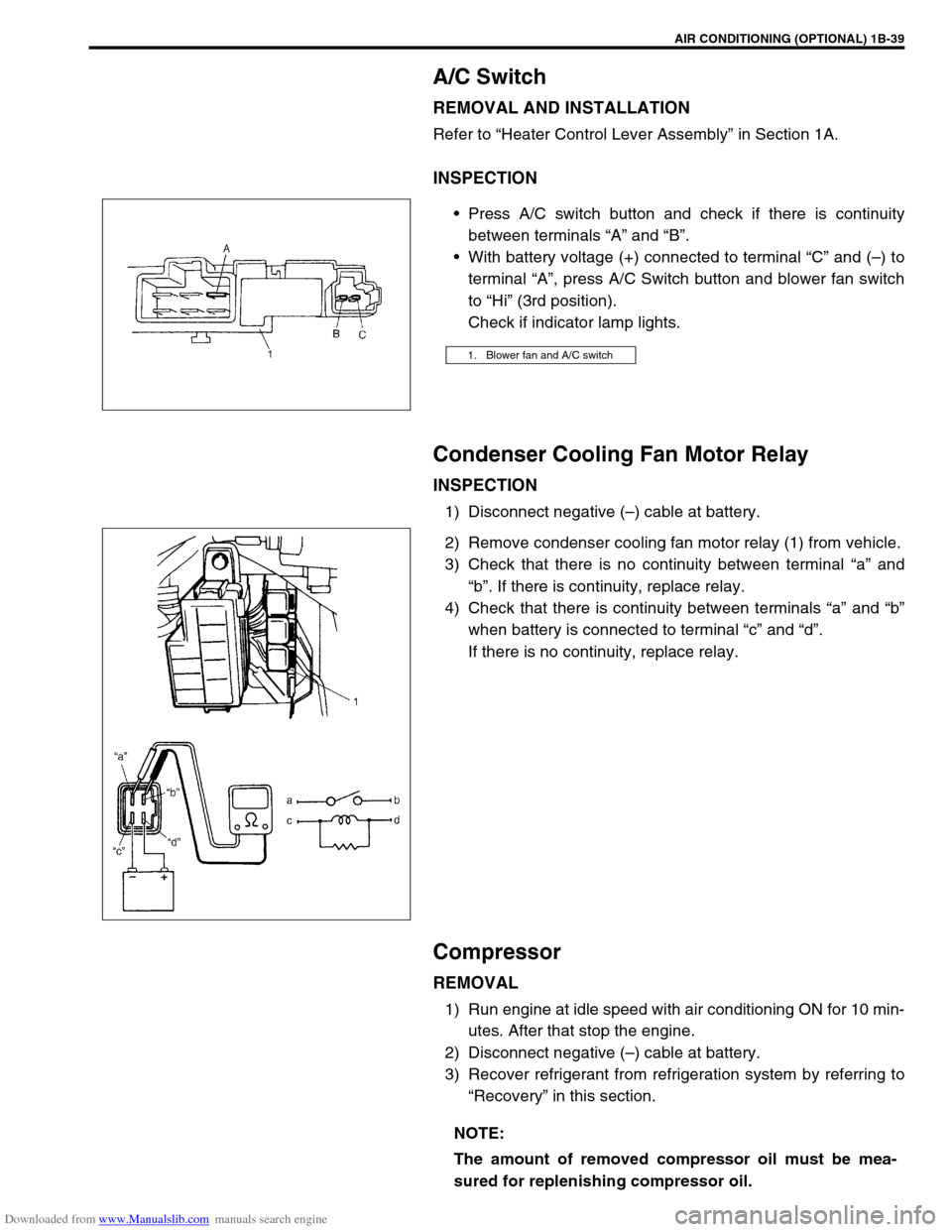
INSPECTION
Press A/C switch button and check if there is continuity
between terminals “A” and “B”.
With battery voltage (+) connected to terminal “C” and (–) to
terminal “A”, press A/C Switch button and blower fan switch
to “Hi” (3rd position).
Check if indicator lamp lights.
Condenser Cooling Fan Motor Relay
INSPECTION
1) Disconnect negative (–) cable at battery.
2) Remove condenser cooling fan motor relay (1) from vehicle.
3) Check that there is no continuity between terminal “a” and
“b”. If there is continuity, replace relay.
4) Check that there is continuity between terminals “a” and “b”
when battery is connected to terminal “c” and “d”.
If there is no continuity, replace relay.
Compressor
REMOVAL
1) Run engine at idle speed with air conditioning ON for 10 min-
utes. After that stop the engine.
2) Disconnect negative (–) cable at battery.
3) Recover refrigerant from refrigeration system by referring to
“Recovery” in this section.
1. Blower fan and A/C switch
NOTE:
The amount of removed compressor oil must be mea-
sured for replenishing compressor oil.
Page 101 of 687

Downloaded from www.Manualslib.com manuals search engine 1B-40 AIR CONDITIONING (OPTIONAL)
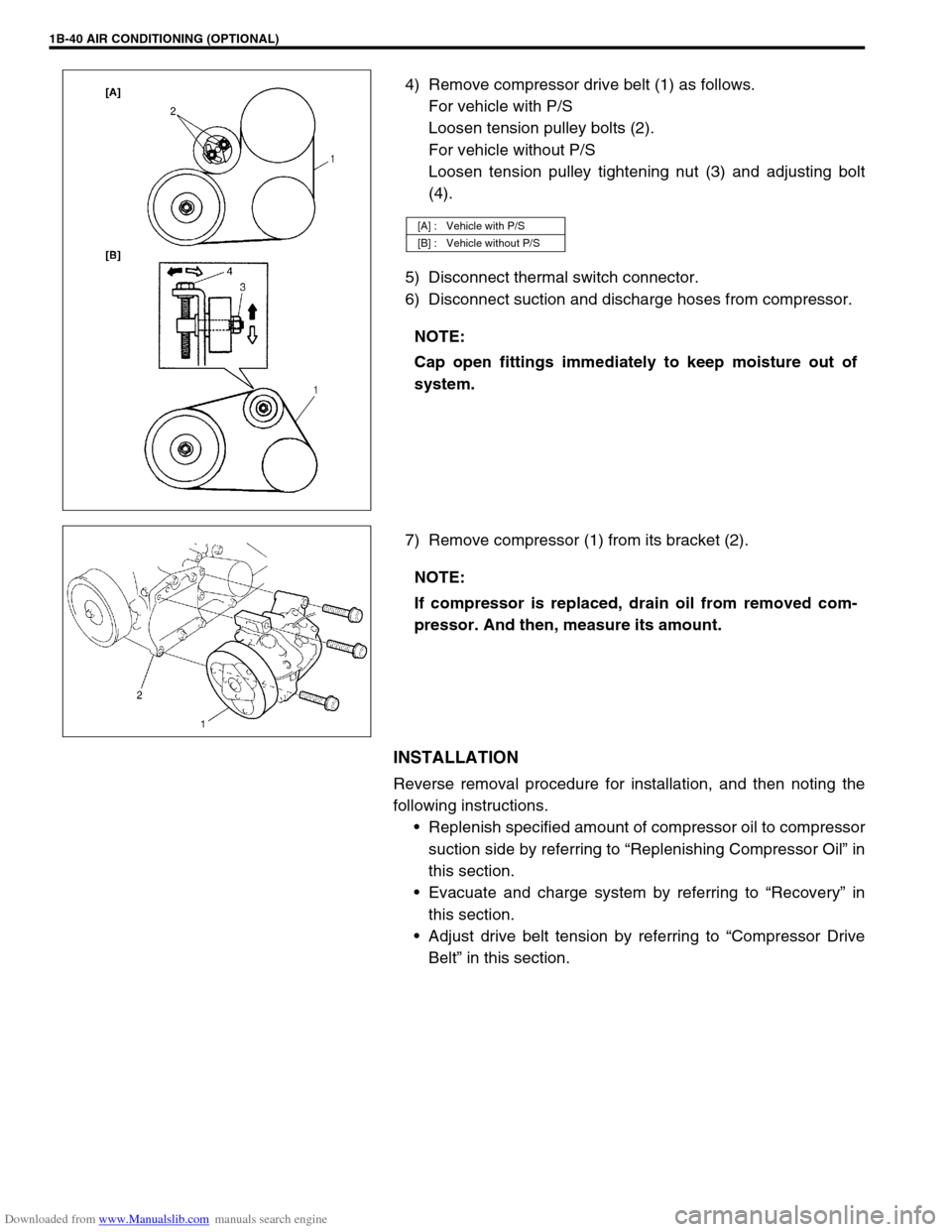
4) Remove compressor drive belt (1) as follows.
For vehicle with P/S
Loosen tension pulley bolts (2).
For vehicle without P/S
Loosen tension pulley tightening nut (3) and adjusting bolt
(4).
5) Disconnect thermal switch connector.
6) Disconnect suction and discharge hoses from compressor.
7) Remove compressor (1) from its bracket (2).
INSTALLATION
Reverse removal procedure for installation, and then noting the
following instructions.
Replenish specified amount of compressor oil to compressor
suction side by referring to “Replenishing Compressor Oil” in
this section.
Evacuate and charge system by referring to “Recovery” in
this section.
Adjust drive belt tension by referring to “Compressor Drive
Belt” in this section.
[A] : Vehicle with P/S
[B] : Vehicle without P/S
NOTE:
Cap open fittings immediately to keep moisture out of
system.
NOTE:
If compressor is replaced, drain oil from removed com-
pressor. And then, measure its amount.