2005 SUZUKI JIMNY Coolant
[x] Cancel search: CoolantPage 584 of 687

Downloaded from www.Manualslib.com manuals search engine ENGINE COOLING 6B-7
Coolant Level
To check level, look at “see-through” reservoir.
It is not necessary to remove radiator cap to check coolant level.
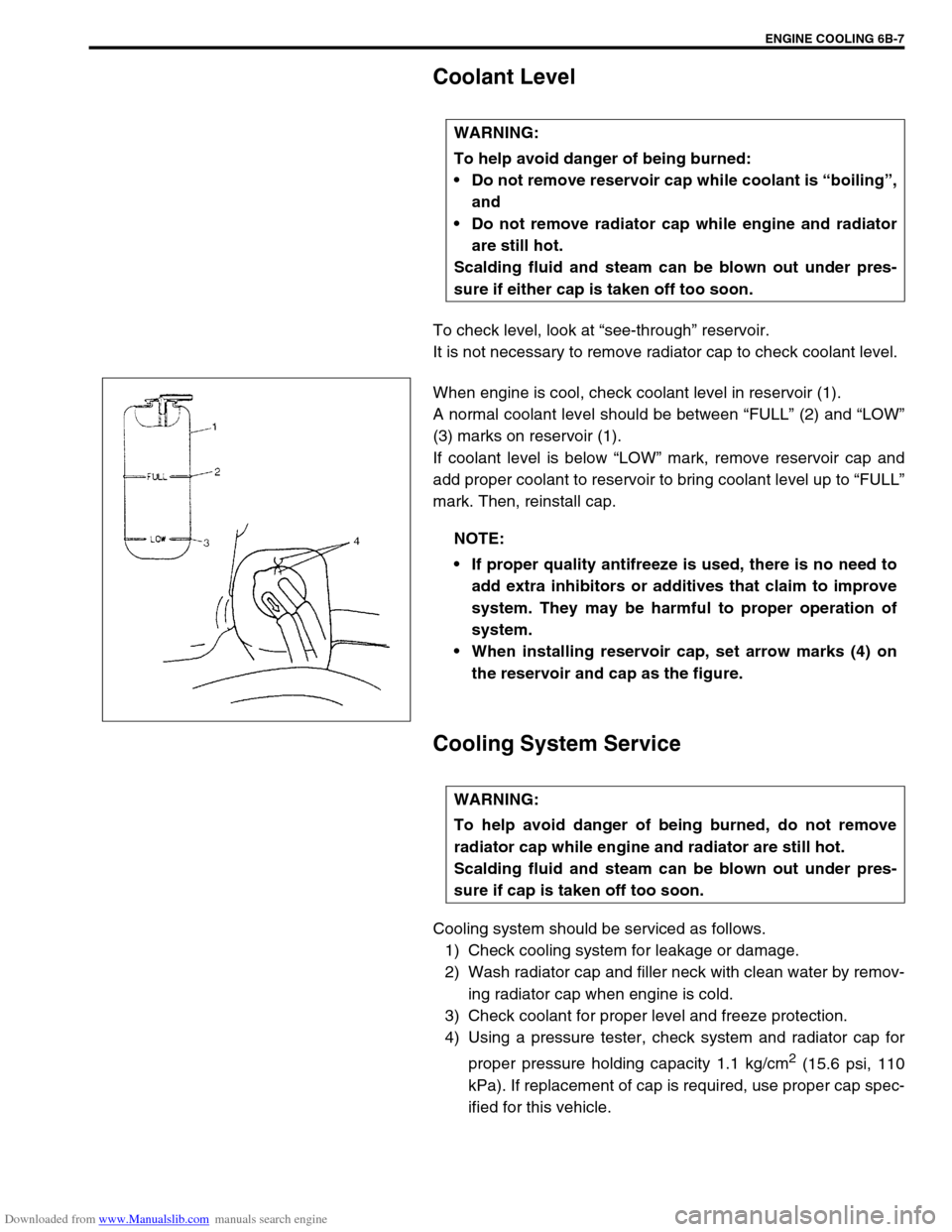
When engine is cool, check coolant level in reservoir (1).
A normal coolant level should be between “FULL” (2) and “LOW”
(3) marks on reservoir (1).
If coolant level is below “LOW” mark, remove reservoir cap and
add proper coolant to reservoir to bring coolant level up to “FULL”
mark. Then, reinstall cap.
Cooling System Service
Cooling system should be serviced as follows.
1) Check cooling system for leakage or damage.
2) Wash radiator cap and filler neck with clean water by remov-
ing radiator cap when engine is cold.
3) Check coolant for proper level and freeze protection.
4) Using a pressure tester, check system and radiator cap for
proper pressure holding capacity 1.1 kg/cm
2 (15.6 psi, 110
kPa). If replacement of cap is required, use proper cap spec-
ified for this vehicle. WARNING:
To help avoid danger of being burned:
Do not remove reservoir cap while coolant is “boiling”,
and
Do not remove radiator cap while engine and radiator
are still hot.
Scalding fluid and steam can be blown out under pres-
sure if either cap is taken off too soon.
NOTE:
If proper quality antifreeze is used, there is no need to
add extra inhibitors or additives that claim to improve
system. They may be harmful to proper operation of
system.
When installing reservoir cap, set arrow marks (4) on
the reservoir and cap as the figure.
WARNING:
To help avoid danger of being burned, do not remove
radiator cap while engine and radiator are still hot.
Scalding fluid and steam can be blown out under pres-
sure if cap is taken off too soon.
Page 585 of 687

Downloaded from www.Manualslib.com manuals search engine 6B-8 ENGINE COOLING
5) Tighten hose clamps and inspect all hoses.
Replace hoses whenever cracked, swollen or otherwise
deteriorated.
6) Clean frontal area of radiator core.
Cooling System Flush and Refill
1) Remove radiator cap when engine is cool:
Turn cap slowly to the left until it reaches a “stop” (Do not
press down while turning it).
Wait until pressure is relieved (indicated by a hissing sound)
then press down on cap and continue to turn it to the left.
2) With radiator cap removed, run engine until upper radiator
hose is hot (this shows that thermostat is open and coolant is
flowing through system).
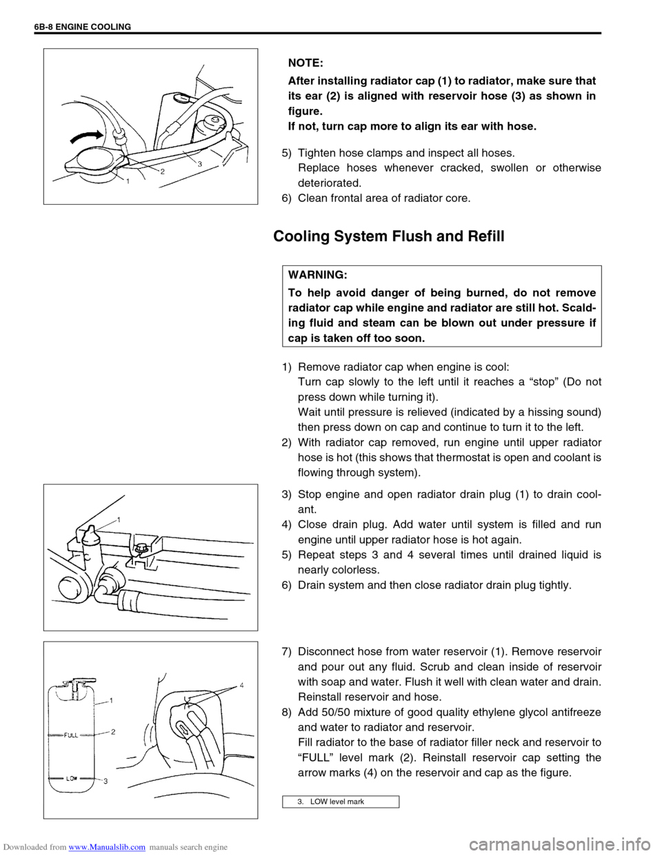
3) Stop engine and open radiator drain plug (1) to drain cool-
ant.
4) Close drain plug. Add water until system is filled and run
engine until upper radiator hose is hot again.
5) Repeat steps 3 and 4 several times until drained liquid is
nearly colorless.
6) Drain system and then close radiator drain plug tightly.
7) Disconnect hose from water reservoir (1). Remove reservoir
and pour out any fluid. Scrub and clean inside of reservoir
with soap and water. Flush it well with clean water and drain.
Reinstall reservoir and hose.
8) Add 50/50 mixture of good quality ethylene glycol antifreeze
and water to radiator and reservoir.
Fill radiator to the base of radiator filler neck and reservoir to
“FULL” level mark (2). Reinstall reservoir cap setting the
arrow marks (4) on the reservoir and cap as the figure. NOTE:
After installing radiator cap (1) to radiator, make sure that
its ear (2) is aligned with reservoir hose (3) as shown in
figure.
If not, turn cap more to align its ear with hose.
WARNING:
To help avoid danger of being burned, do not remove
radiator cap while engine and radiator are still hot. Scald-
ing fluid and steam can be blown out under pressure if
cap is taken off too soon.
3. LOW level mark
Page 586 of 687

Downloaded from www.Manualslib.com manuals search engine ENGINE COOLING 6B-9
9) Run engine, with radiator cap removed, until radiator upper
hose is hot.
10) With engine idling, add coolant to radiator until level reaches
the bottom of filler neck. Install radiator cap, making sure
that the ear of cap lines up with reservoir hose.
Water Pump Belt Tension
1) Inspect belt for cracks, cuts, deformation, wear and cleanli-
ness. If it is necessary to replace belt, refer to “Water Pump
Belt and Cooling Fan” in this section.
2) Check belt for tension. Belt is in proper tension when it
deflects 4.5 to 5.5 mm (0.18 – 0.22 in.) under thumb pres-
sure (about 10 kg or 22 lb.).
Water pump belt tension
“a” : 4.5 – 5.5 mm (0.18 – 0.22 in.) as deflection / 10 kg (22
lbs)
3) If belt is too tight or too loose, adjust it to proper tension by
displacing generator position.
4) Tighten generator adjusting bolt and pivot bolts as specified
torque.
Tightening torque
Generator adjusting bolt (a) : 23 N·m (2.3 kg-m, 17.0 lb-ft)
Generator pivot bolts (b) : 50 N·m (5.0 kg-m, 36.0 lb-ft)
5) Connect negative cable at battery terminal.WARNING:
Disconnect negative cable at battery before checking and
adjusting belt tension.
NOTE:
When replacing belt with a new one, adjust belt tension
to 3 – 4 mm (0.12 – 0.16 in.).
Page 587 of 687

Downloaded from www.Manualslib.com manuals search engine 6B-10 ENGINE COOLING
On-Vehicle Service
Cooling System Component
CAUTION:
Check to make sure that engine coolant temperature is cold before removing any part of cooling
system.
Disconnect negative cable at battery before removing any part.
1. Radiator 6. Thermostat 11. Water outlet cap
2. Reservoir 7. Thermostat cap 12. Thermostat case outlet pipe
3. Cooling fan shroud 8. Radiator outlet pipe 13. Thermostat cap bolt
4. Water outlet pipe 9. Heater pipe 14. Thermostat case bolt
5. Thermostat case 10. ECT sensor Tightening Torque
814 25 N·m (2.5 kg-m) 10 15 N·m (1.5 kg-m)
12 5
6
7
13 11 N·m
(1.1 kg-m) 119421
3
Page 588 of 687

Downloaded from www.Manualslib.com manuals search engine ENGINE COOLING 6B-11
Coolant Draining
1) Remove radiator cap (1).
2) Loosen drain plug on radiator to drain coolant.
3) After draining coolant, be sure to tighten drain plug securely.
4) Fill cooling system. Refer to “Coolant” in this section.
Cooling Water Pipes or Hoses
REMOVAL
1) Drain cooling system.
2) To remove water pipes or hoses, loosen screw on each pipe
or hose clip and pull hose end off.
INSTALLATION
Install removed parts in reverse order of removal procedure, not-
ing the following.
Tighten each clamp bolt securely.
Refill cooling system with proper coolant, referring to
description on “Coolant” and “Cooling System Flush and
Refill” in this section.
Thermostat
REMOVAL
1) Drain cooling system and tighten drain plug.
2) Remove intake manifold, referring to “Throttle Body and
Intake Manifold” in Section 6A1.
3) Disconnect thermostat cap (1) from thermostat case (2).
4) Remove thermostat (3).
Page 591 of 687

Downloaded from www.Manualslib.com manuals search engine 6B-14 ENGINE COOLING
Radiator
REMOVAL
1) Drain cooling system.
2) Remove radiator shroud.
3) Disconnect water hoses from radiator.
4) With automatic transmission (A/T) vehicle, disconnect addi-
tional two fluid hoses from radiator.
Place some container under radiator to receive A/T fluid
which will flow out when hose is disconnected.
5) Install radiator protection board to between radiator and
cooling fan.
6) Remove radiator after removing two bolts (1).
INSPECTION
If the water side of the radiator is found excessively rusted or cov-
ered with scales, clean it by flushing with the radiator cleaner
compound.
This flushing should be carried out at regular intervals for scale or
rust formation advances with time even where a recommended
type of coolant is used. Periodical flushing will prove more eco-
nomical.
Inspect the radiator cores and straighten the flattened or bent
fins, if any. Clean the cores, removing road grimes and trashes.
Excessive rust or scale formation on the wet side of the radiator
lowers the cooling efficiency.
Flattened or bent fins obstruct the flow of air through the core to
impede heat dissipation.
Radiator flushing interval recommended
Two years
INSTALLATION
Reverse removal procedures.
NOTE:
Refill cooling system with proper coolant referring to
“Coolant” and “Cooling System Flush and Refill” in
this section.
With automatic transmission vehicle, fill A/T fluid up to
specified level. For procedure to check A/T fluid and its
level, refer to “Changing Fluid” in Section 7B.
After installation, check each joint for leakage.
Page 594 of 687

Downloaded from www.Manualslib.com manuals search engine ENGINE COOLING 6B-17
Required Service Material
Tightening Torque Specification
MaterialRecommended SUZUKI product
(Part Number)Use
Ethylene glycol base
coolant (Anti-freeze /
Anti-corrosion coolant)–Additive to engine cooling system for improving
cooling efficiency and for protection against
rusting.
SealantSUZUKI BOND NO.1207C
(99000 – 31150)To apply to water pump mating surface.
Fastening partTightening torque
Nm kg-m lb-ft
Water pump bolt 23 2.3 17.0
Thermostat cap bolt 11 1.1 8.0
Thermostat case bolt 25 2.5 18.0
Fun clutch bolt 11 1.1 8.0
Page 606 of 687

Downloaded from www.Manualslib.com manuals search engine ENGINE AND EMISSION CONTROL SYSTEM 6E-1
6F1
6F2
6G
7C1
7D
7E
7A
7A1
7B1
7C1
7D
7E
7F
8A
8B
8C
8D
6H
6E
10
10A
10B
SECTION 6E
ENGINE AND EMISSION CONTROL SYSTEM
CONTENTS
General Description ....................................... 6E-3
Air Intake System ......................................... 6E-5
Fuel Delivery System ................................... 6E-6
Fuel pump ................................................ 6E-6
Electronic Control System ............................ 6E-7
Engine & emission control input / output
table.......................................................... 6E-8
On-Vehicle Service....................................... 6E-15
Accelerator cable adjustment ................. 6E-15
Idle speed / idle air control (IAC) duty
inspection ............................................... 6E-15
Idle mixture inspection / adjustment
(vehicle without heated oxygen
sensor) ................................................... 6E-17
Air Intake System ....................................... 6E-18
Throttle body .......................................... 6E-18
Idle air control valve (IAC valve)............. 6E-21
Fuel Delivery System ................................. 6E-22
Fuel pressure inspection ........................ 6E-22
Fuel pump .............................................. 6E-23
Fuel pressure regulator .......................... 6E-24
Fuel injector ............................................ 6E-25
Electronic Control System .......................... 6E-29Engine control module (ECM) ................ 6E-29
Manifold absolute pressure sensor (MAP
sensor) ................................................... 6E-29
Throttle position sensor (TP sensor) ...... 6E-30
Intake air temperature sensor
(IAT sensor) ........................................... 6E-31
Engine coolant temperature sensor
(ECT sensor) .......................................... 6E-32
Heated oxygen sensor
(Sensor-1 and sensor-2) ........................ 6E-33
Camshaft position sensor....................... 6E-34
Crankshaft position sensor..................... 6E-35
Vehicle speed sensor (VSS) .................. 6E-36
Fuel level sensor (GAUGE).................... 6E-36
Knock sensor ......................................... 6E-36
Main relay, fuel pump relay and A/C
condenser fan control relay .................... 6E-36
Fuel cut operation .................................. 6E-37
A/C condenser fan control system ......... 6E-37
A/C condenser fan ................................. 6E-37
Output signals of throttle valve opening
and engine coolant temp.
(Vehicle with A/T only) ........................... 6E-38
Emission Control System ........................... 6E-38 WARNING:
For vehicles equipped with Supplemental Restraint (Air Bag) System:
Service on and around the air bag system components or wiring must be performed only by an
authorized SUZUKI dealer. Refer to “Air Bag System Components and Wiring Location View” under
“General Description” in air bag system section in order to confirm whether you are performing ser-
vice on or near the air bag system components or wiring. Please observe all WARNINGS and “Ser-
vice Precautions” under “On-Vehicle Service” in air bag system section before performing service
on or around the air bag system components or wiring. Failure to follow WARNINGS could result in
unintentional activation of the system or could render the system inoperative. Either of these two
conditions may result in severe injury.
Technical service work must be started at least 90 seconds after the ignition switch is turned to the
“LOCK” position and the negative cable is disconnected from the battery. Otherwise, the system
may be activated by reserve energy in the Sensing and Diagnostic Module (SDM).
NOTE:
Whether following systems (parts) are used in the particular vehicle or not depends on specifications.
Be sure to bear this in mind when performing service work.
EGR valve
Heated oxygen sensor (s) or CO adjusting resistor
Three way catalytic converter (TWC) and warm up three-way catalytic converter (WU-TWC)