Page 446 of 687

Downloaded from www.Manualslib.com manuals search engine ENGINE GENERAL INFORMATION AND DIAGNOSIS 6-89
DTC CONFIRMATION PROCEDURE
1) Turn ignition switch OFF.
Clear DTC with ignition switch ON, check vehicle and environmental condition for :
–Altitude (barometric pressure) : 2400 m, 8000 ft or less (560 mmHg, 75 kPa or more)
–Ambient temp. : –10 °C, 14 °F or higher
–Intake air temp. : 70 °C, 158 °F or lower
–Engine coolant temp. : 70 – 110 °C, 158 – 230 °F
2) Start engine and drive vehicle at 35 – 45 mph, 55 – 65 km/h for 8 min. or longer.
While this driving, if “Catalyst Monitoring TEST COMPLETED” is displayed in “READINESS TESTS” mode
and DTC is not displayed in “DTC” mode, confirmation test is completed.
If “TEST NOT COMPLTD” is still being displayed, continue test driving.
3) Decrease vehicle speed at 30 – 40 mph, 50 – 60 km/h, and hold throttle valve at that opening position for 2
min. and confirm that short term fuel trim vary within – 20% – +20% range.
4) Stop vehicle (do not turn ignition switch OFF) and confirm test results according to following “Test Result
Confirmation Flow Table”. DTC DETECTING CONDITION POSSIBLE CAUSE
While vehicle running at constant speed under other than
high load.
Time from rich or lean switching command is output till HO2S-
2 output voltage crosses 0.45 V less than specified value.
✱
✱✱ ✱2 driving cycle detection logic, monitoring once / 1 driving.Exhaust gas leak
Three way catalytic converter malfunction
Fuel system malfunction
HO2S-2 malfunction
HO2S-1 malfunction
WARNING:
When performing a road test, select a place where there is no traffic or possibility of a traffic acci-
dent and be very careful during testing to avoid occurrence of an accident.
Road test should be carried out with 2 persons, a driver and a tester, on a level road.
Page 469 of 687

Downloaded from www.Manualslib.com manuals search engine 6-112 ENGINE GENERAL INFORMATION AND DIAGNOSIS
Table B-3 Fuel Pressure Check
INSPECTION
1. Injector 3. Fuel pump (B) : Hose
2. Delivery pipe (A) : Fuel pressure gauge (C) : Attachment
Step Action Yes No
1 Check Fuel Pressure (Refer to Section 6E for
details).
1) Release fuel pressure from fuel feed line.
2) Install fuel pressure gauge. See Fig.1.
3) Check fuel pressure by repeating ignition
switch ON and OFF.
Is fuel pressure then 270 – 310 kPa
(2.7 - 3.1 kg/cm
2, 38.4 – 44.0 psi)?Go to Step 2. Go to Step 4.
2
Is 250 kPa (2.5 kg/cm
2, 35.6 psi) or higher fuel
pressure retained for 1 minute after fuel pump is
stopped at Step 1?Normal fuel pressure. Go to Step 3.
3 Is there fuel leakage from fuel feed line hose,
pipe or their joint?Fuel leakage from hose,
pipe or joint.Faulty fuel pressure regu-
lator.
4 Was fuel pressure higher than spec. in Step 1? Faulty fuel pressure regu-
lator.Clogged fuel filter,
Restricted fuel feed hose
or pipe, Faulty fuel pump
or Fuel leakage from hose
connection in fuel tank.
Page 485 of 687
Downloaded from www.Manualslib.com manuals search engine 6A1-4 ENGINE MECHANICAL (M13 ENGINE)
Diagnosis
Diagnosis Table
Refer to “Engine Diagnosis Table” in Section 6.
Compression Check
Check compression pressure on all 4 cylinders as follows:
1) Warm up engine.
2) Stop engine after warming up.
3) Disconnect accelerator cable (1) from clamp (2) (For left
hand steering vehicle only).
4) Remove cylinder head upper cover (3).
5) Disconnect ignition coil couplers (1).
6) Remove ignition coil assemblies (2) with high-tension cord
(3).
7) Remove all spark plugs.
8) Disconnect fuel injector wires (4) at the coupler.
9) Install special tools (Compression gauge) into spark plug
hole.
Special tool
(A) : 09915-64510-001
(B) : 09915-64510-002
(C) : 09915-64530
(D) : 09915-67010 NOTE:
After warming up engine, place transmission gear shift
lever in “Neutral” (shift selector lever to “P” range for A/T
model), and set parking brake and block drive wheels.
Page 486 of 687
Downloaded from www.Manualslib.com manuals search engine ENGINE MECHANICAL (M13 ENGINE) 6A1-5
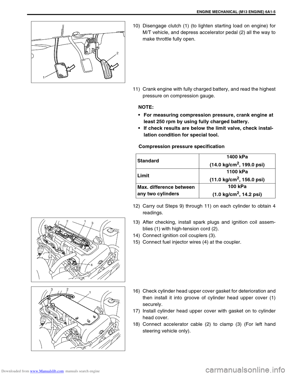
10) Disengage clutch (1) (to lighten starting load on engine) for
M/T vehicle, and depress accelerator pedal (2) all the way to
make throttle fully open.
11) Crank engine with fully charged battery, and read the highest
pressure on compression gauge.
Compression pressure specification
12) Carry out Steps 9) through 11) on each cylinder to obtain 4
readings.
13) After checking, install spark plugs and ignition coil assem-
blies (1) with high-tension cord (2).
14) Connect ignition coil couplers (3).
15) Connect fuel injector wires (4) at the coupler.
16) Check cylinder head upper cover gasket for deterioration and
then install it into groove of cylinder head upper cover (1)
securely.
17) Install cylinder head upper cover with gasket on to cylinder
head cover.
18) Connect accelerator cable (2) to clamp (3) (For left hand
steering vehicle only).
NOTE:
For measuring compression pressure, crank engine at
least 250 rpm by using fully charged battery.
If check results are below the limit valve, check instal-
lation condition for special tool.
Standard1400 kPa
(14.0 kg/cm
2, 199.0 psi)
Limit1100 kPa
(11.0 kg/cm
2, 156.0 psi)
Max. difference between
any two cylinders100 kPa
(1.0 kg/cm
2, 14.2 psi)
Page 499 of 687
Downloaded from www.Manualslib.com manuals search engine 6A1-18 ENGINE MECHANICAL (M13 ENGINE)
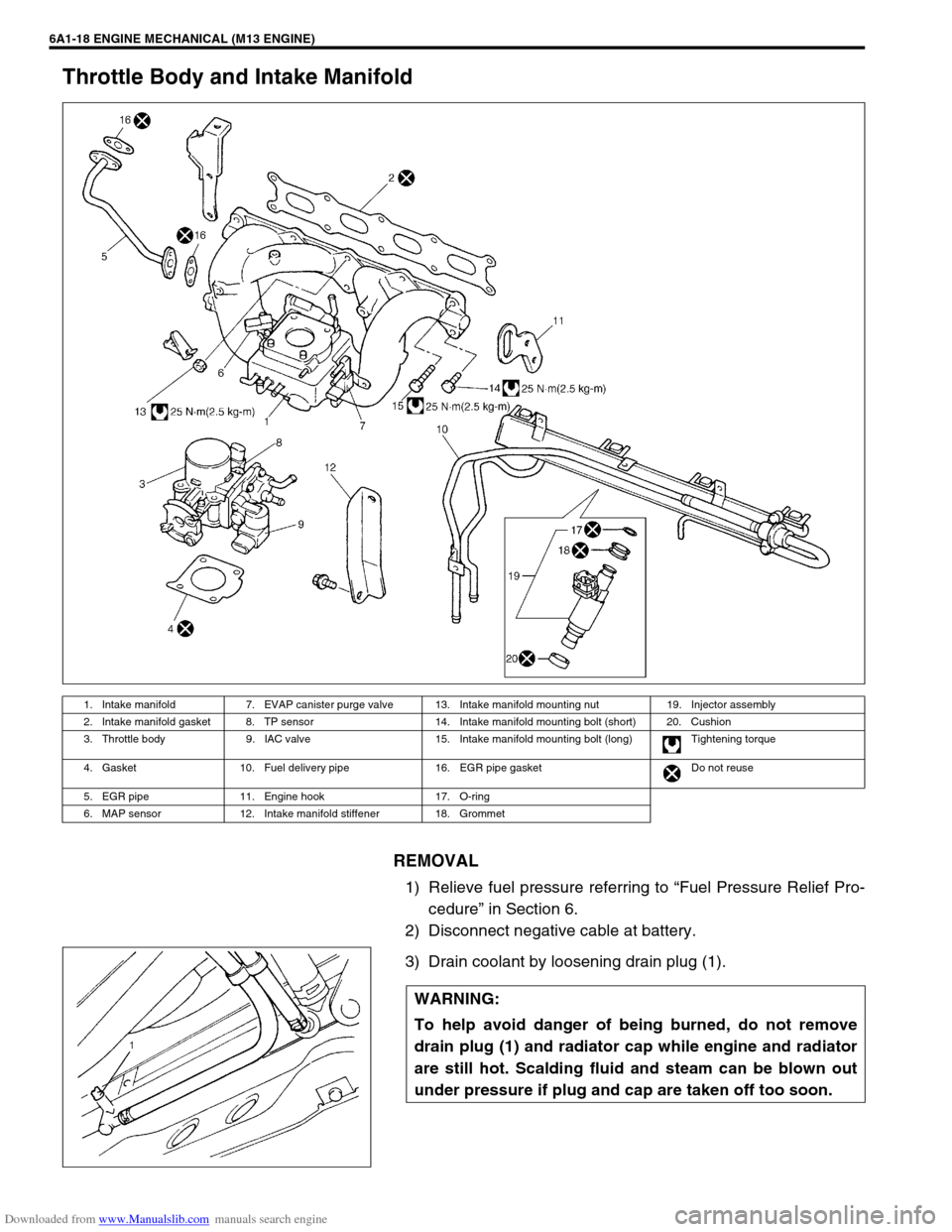
Throttle Body and Intake Manifold
REMOVAL
1) Relieve fuel pressure referring to “Fuel Pressure Relief Pro-
cedure” in Section 6.
2) Disconnect negative cable at battery.
3) Drain coolant by loosening drain plug (1).
1. Intake manifold 7. EVAP canister purge valve 13. Intake manifold mounting nut 19. Injector assembly
2. Intake manifold gasket 8. TP sensor 14. Intake manifold mounting bolt (short) 20. Cushion
3. Throttle body 9. IAC valve 15. Intake manifold mounting bolt (long) Tightening torque
4. Gasket 10. Fuel delivery pipe 16. EGR pipe gasket Do not reuse
5. EGR pipe 11. Engine hook 17. O-ring
6. MAP sensor 12. Intake manifold stiffener 18. Grommet
WARNING:
To help avoid danger of being burned, do not remove
drain plug (1) and radiator cap while engine and radiator
are still hot. Scalding fluid and steam can be blown out
under pressure if plug and cap are taken off too soon.
Page 500 of 687
Downloaded from www.Manualslib.com manuals search engine ENGINE MECHANICAL (M13 ENGINE) 6A1-19
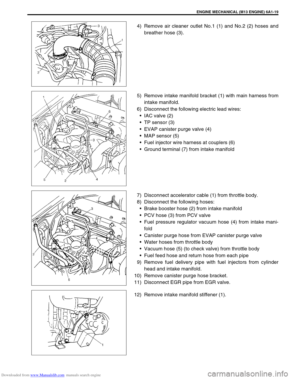
4) Remove air cleaner outlet No.1 (1) and No.2 (2) hoses and
breather hose (3).
5) Remove intake manifold bracket (1) with main harness from
intake manifold.
6) Disconnect the following electric lead wires:
IAC valve (2)
TP sensor (3)
EVAP canister purge valve (4)
MAP sensor (5)
Fuel injector wire harness at couplers (6)
Ground terminal (7) from intake manifold
7) Disconnect accelerator cable (1) from throttle body.
8) Disconnect the following hoses:
Brake booster hose (2) from intake manifold
PCV hose (3) from PCV valve
Fuel pressure regulator vacuum hose (4) from intake mani-
fold
Canister purge hose from EVAP canister purge valve
Water hoses from throttle body
Vacuum hose (5) (to check valve) from throttle body
Fuel feed hose and return hose from each pipe
9) Remove fuel delivery pipe with fuel injectors from cylinder
head and intake manifold.
10) Remove canister purge hose bracket.
11) Disconnect EGR pipe from EGR valve.
12) Remove intake manifold stiffener (1).
Page 530 of 687
Downloaded from www.Manualslib.com manuals search engine ENGINE MECHANICAL (M13 ENGINE) 6A1-49
REMOVAL
1) Relieve fuel pressure referring to “Fuel Pressure Relief Pro-
cedure” in Section 6.
2) Disconnect negative cable at battery.
3) Drain engine oil.
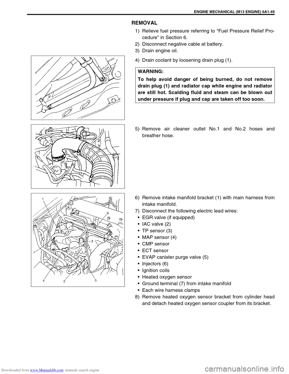
4) Drain coolant by loosening drain plug (1).
5) Remove air cleaner outlet No.1 and No.2 hoses and
breather hose.
6) Remove intake manifold bracket (1) with main harness from
intake manifold.
7) Disconnect the following electric lead wires:
EGR valve (if equipped)
IAC valve (2)
TP sensor (3)
MAP sensor (4)
CMP sensor
ECT sensor
EVAP canister purge valve (5)
Injectors (6)
Ignition coils
Heated oxygen sensor
Ground terminal (7) from intake manifold
Each wire harness clamps
8) Remove heated oxygen sensor bracket from cylinder head
and detach heated oxygen sensor coupler from its bracket. WARNING:
To help avoid danger of being burned, do not remove
drain plug (1) and radiator cap while engine and radiator
are still hot. Scalding fluid and steam can be blown out
under pressure if plug and cap are taken off too soon.
Page 543 of 687
Downloaded from www.Manualslib.com manuals search engine 6A1-62 ENGINE MECHANICAL (M13 ENGINE)
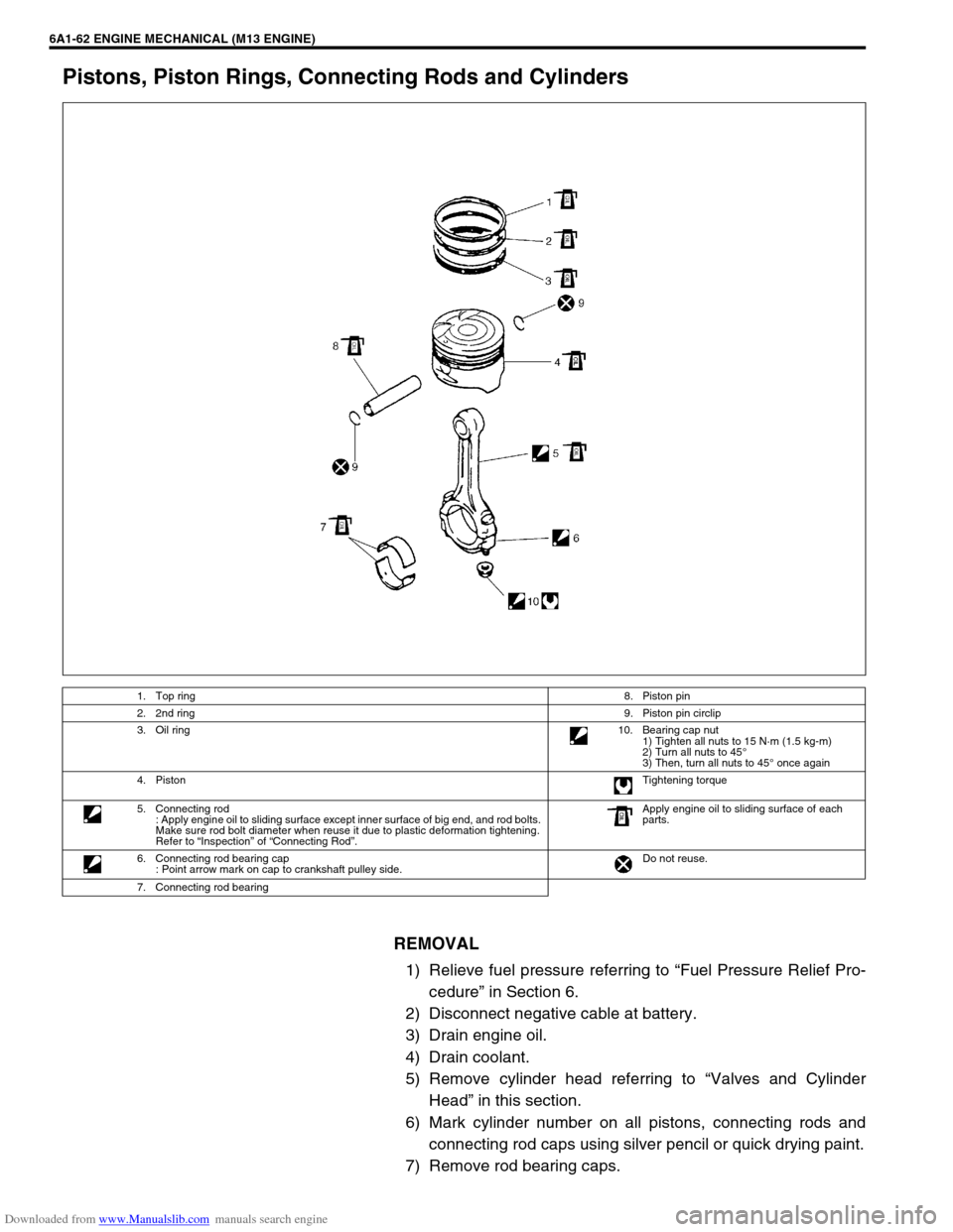
Pistons, Piston Rings, Connecting Rods and Cylinders
REMOVAL
1) Relieve fuel pressure referring to “Fuel Pressure Relief Pro-
cedure” in Section 6.
2) Disconnect negative cable at battery.
3) Drain engine oil.
4) Drain coolant.
5) Remove cylinder head referring to “Valves and Cylinder
Head” in this section.
6) Mark cylinder number on all pistons, connecting rods and
connecting rod caps using silver pencil or quick drying paint.
7) Remove rod bearing caps.
1. Top ring8. Piston pin
2. 2nd ring9. Piston pin circlip
3. Oil ring10. Bearing cap nut
1) Tighten all nuts to 15 N·m (1.5 kg-m)
2) Turn all nuts to 45°
3) Then, turn all nuts to 45° once again
4. PistonTightening torque
5. Connecting rod
: Apply engine oil to sliding surface except inner surface of big end, and rod bolts.
Make sure rod bolt diameter when reuse it due to plastic deformation tightening.
Refer to “Inspection” of “Connecting Rod”.Apply engine oil to sliding surface of each
parts.
6. Connecting rod bearing cap
: Point arrow mark on cap to crankshaft pulley side.Do not reuse.
7. Connecting rod bearing