Page 280 of 687
Downloaded from www.Manualslib.com manuals search engine BRAKES 5-19
PIPE
Inspect the tube for damage, cracks, dents and corrosion. If any
defect is found, replace it.
Front Disc Brake
1. Caliper pin bolt 10. Carrier bolt
2. Boot11. Brake caliper carrier
3. Cylinder slide bush
: Apply rubber grease to mating surface of caliper12. Pad clip
4. Bleeder plug cap 13. Disc brake caliper
5. Bleeder plug 14. Disc brake pad
6. Anti noise shim 15. Piston seal
: Apply brake fluid to all around part of piston seal
7. Disc brake piston
: Apply brake fluid to contact surface of cylinderTightening torque
8. Cylinder bootDo not reuse.
9. Seat ring (boot ring)
Page 289 of 687
Downloaded from www.Manualslib.com manuals search engine 5-28 BRAKES
CHECK FOR FRONT BRAKE AFTER INSTALLATION
Mount tires and make certain that they rotate smoothly, with a
force of less than 3.0 kg (6.6 Ib).
If tire rotation is heavy, check the following:
Piston, piston seal and cylinder slide bush of caliper for
installation.
Wheel bearings for breakage.
Disc for flatness (Improper flatness brings disc into contact
with lining during rotation and makes rotation heavy).
To check this, measure disc deflection.NOTE:
For above check the following must be observed.
Jack up front wheels, both right and left, off the
ground.
Shift transfer shift lever to 2H (rear wheel) position (if
equipped) and start engine for a few seconds then
stop.
Side figure shows outer periphery of tire.
Be careful not to depress brake pedal when checking
tire for rotation.
1. String
2. Spring measure
Page 308 of 687
Downloaded from www.Manualslib.com manuals search engine BRAKES 5-47
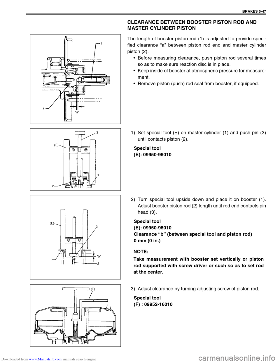
CLEARANCE BETWEEN BOOSTER PISTON ROD AND
MASTER CYLINDER PISTON
The length of booster piston rod (1) is adjusted to provide speci-
fied clearance “a” between piston rod end and master cylinder
piston (2).
Before measuring clearance, push piston rod several times
so as to make sure reaction disc is in place.
Keep inside of booster at atmospheric pressure for measure-
ment.
Remove piston (push) rod seal from booster, if equipped.
1) Set special tool (E) on master cylinder (1) and push pin (3)
until contacts piston (2).
Special tool
(E): 09950-96010
2) Turn special tool upside down and place it on booster (1).
Adjust booster piston rod (2) length until rod end contacts pin
head (3).
Special tool
(E): 09950-96010
Clearance “b” (between special tool and piston rod)
0 mm (0 in.)
3) Adjust clearance by turning adjusting screw of piston rod.
Special tool
(F) : 09952-16010
NOTE:
Take measurement with booster set vertically or piston
rod supported with screw driver or such so as to set rod
at the center.
Page 311 of 687
Downloaded from www.Manualslib.com manuals search engine 5-50 BRAKES
REMOVAL
1) Raise, suitably support vehicle. Remove wheel if necessary.
2) Clean dirt and foreign material from both hose end or pipe end fittings. Remove brake hose and pipe.
INSTALLATION
1) Install brake hose and pipe by reversing removal procedure, noting the following points.
For installation, make sure that steering wheel is in straightforward position and hose has no twist or kink.
Check to make sure that hose doesn’t contact any part of suspension, both in extreme right and extreme left
turn conditions. If it does at any point, remove and correct. Fill and maintain brake fluid level in reservoir.
Bleed brake system.
2) Perform brake test and check installed part for fluid leakage.
Page 352 of 687
Downloaded from www.Manualslib.com manuals search engine ANTILOCK BRAKE SYSTEM (ABS) 5E-35
Front Wheel Sensor Ring
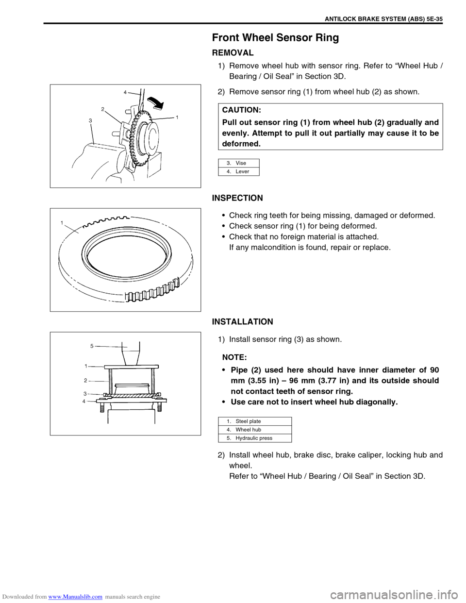
REMOVAL
1) Remove wheel hub with sensor ring. Refer to “Wheel Hub /
Bearing / Oil Seal” in Section 3D.
2) Remove sensor ring (1) from wheel hub (2) as shown.
INSPECTION
Check ring teeth for being missing, damaged or deformed.
Check sensor ring (1) for being deformed.
Check that no foreign material is attached.
If any malcondition is found, repair or replace.
INSTALLATION
1) Install sensor ring (3) as shown.
2) Install wheel hub, brake disc, brake caliper, locking hub and
wheel.
Refer to “Wheel Hub / Bearing / Oil Seal” in Section 3D. CAUTION:
Pull out sensor ring (1) from wheel hub (2) gradually and
evenly. Attempt to pull it out partially may cause it to be
deformed.
3. Vise
4. Lever
NOTE:
Pipe (2) used here should have inner diameter of 90
mm (3.55 in) – 96 mm (3.77 in) and its outside should
not contact teeth of sensor ring.
Use care not to insert wheel hub diagonally.
1. Steel plate
4. Wheel hub
5. Hydraulic press
Page 400 of 687
Downloaded from www.Manualslib.com manuals search engine ENGINE GENERAL INFORMATION AND DIAGNOSIS 6-43
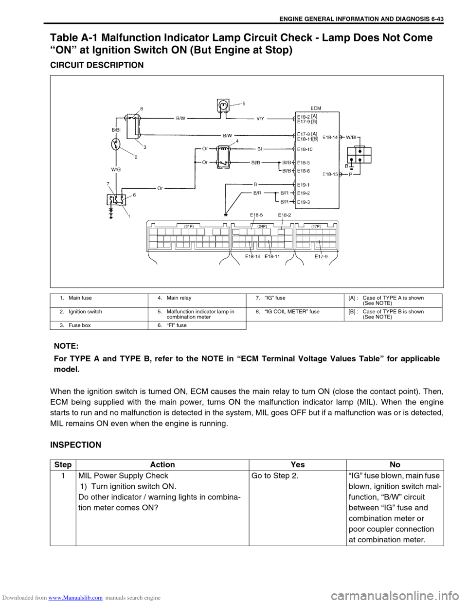
Table A-1 Malfunction Indicator Lamp Circuit Check - Lamp Does Not Come
“ON” at Ignition Switch ON (But Engine at Stop)
CIRCUIT DESCRIPTION
When the ignition switch is turned ON, ECM causes the main relay to turn ON (close the contact point). Then,
ECM being supplied with the main power, turns ON the malfunction indicator lamp (MIL). When the engine
starts to run and no malfunction is detected in the system, MIL goes OFF but if a malfunction was or is detected,
MIL remains ON even when the engine is running.
INSPECTION
1. Main fuse 4. Main relay 7.“IG” fuse [A] : Case of TYPE A is shown
(See NOTE)
2. Ignition switch 5. Malfunction indicator lamp in
combination meter8.“IG COIL METER” fuse [B] : Case of TYPE B is shown
(See NOTE)
3. Fuse box 6.“FI” fuse
NOTE:
For TYPE A and TYPE B, refer to the NOTE in “ECM Terminal Voltage Values Table” for applicable
model.
Step Action Yes No
1 MIL Power Supply Check
1) Turn ignition switch ON.
Do other indicator / warning lights in combina-
tion meter comes ON?Go to Step 2.“IG” fuse blown, main fuse
blown, ignition switch mal-
function, “B/W” circuit
between “IG” fuse and
combination meter or
poor coupler connection
at combination meter.
Page 403 of 687
Downloaded from www.Manualslib.com manuals search engine 6-46 ENGINE GENERAL INFORMATION AND DIAGNOSIS
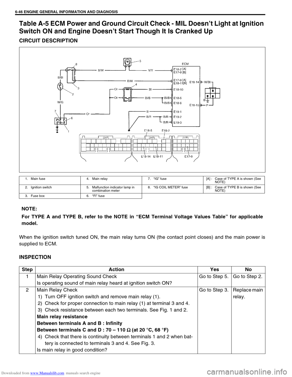
Table A-5 ECM Power and Ground Circuit Check - MIL Doesn’t Light at Ignition
Switch ON and Engine Doesn’t Start Though It Is Cranked Up
CIRCUIT DESCRIPTION
When the ignition switch tuned ON, the main relay turns ON (the contact point closes) and the main power is
supplied to ECM.
INSPECTION
1. Main fuse 4. Main relay 7.“IG” fuse [A] : Case of TYPE A is shown (See
NOTE)
2. Ignition switch 5. Malfunction indicator lamp in
combination meter8.“IG COIL METER” fuse [B] : Case of TYPE B is shown (See
NOTE)
3. Fuse box 6.“FI” fuse
NOTE:
For TYPE A and TYPE B, refer to the NOTE in “ECM Terminal Voltage Values Table” for applicable
model.
Step Action Yes No
1 Main Relay Operating Sound Check
Is operating sound of main relay heard at ignition switch ON?Go to Step 5. Go to Step 2.
2 Main Relay Check
1) Turn OFF ignition switch and remove main relay (1).
2) Check for proper connection to main relay (1) at terminal 3 and 4.
3) Check resistance between each two terminals. See Fig. 1 and 2.
Main relay resistance
Between terminals A and B : Infinity
Between terminals C and D : 70 – 110
Ω
Ω Ω Ω (at 20 °C, 68 °F)
4) Check that there is continuity between terminals 1 and 2 when bat-
tery is connected to terminals 3 and 4. See Fig. 3.
Is main relay in good condition?Go to Step 3. Replace main
relay.
Page 535 of 687
Downloaded from www.Manualslib.com manuals search engine 6A1-54 ENGINE MECHANICAL (M13 ENGINE)
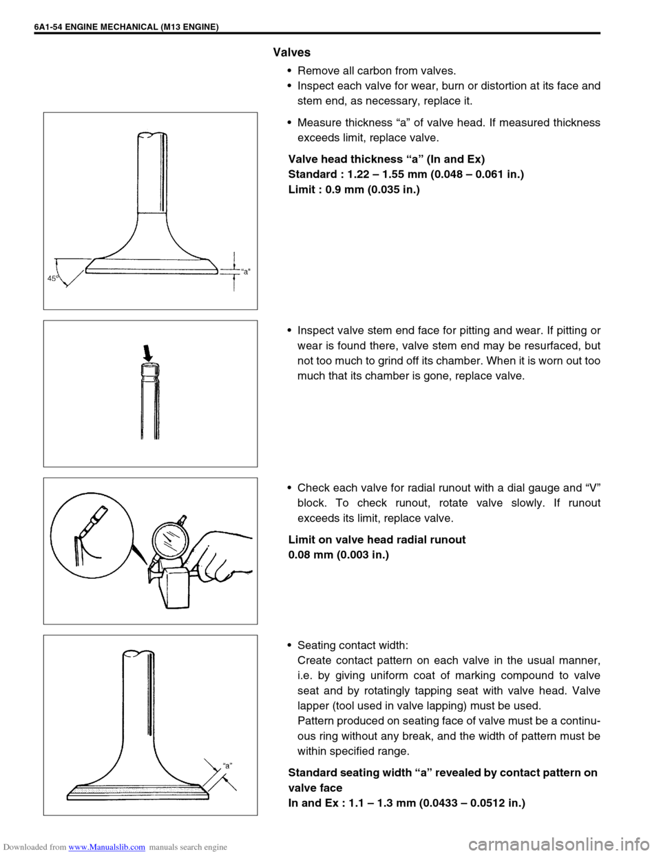
Valves
Remove all carbon from valves.
Inspect each valve for wear, burn or distortion at its face and
stem end, as necessary, replace it.
Measure thickness “a” of valve head. If measured thickness
exceeds limit, replace valve.
Valve head thickness “a” (In and Ex)
Standard : 1.22 – 1.55 mm (0.048 – 0.061 in.)
Limit : 0.9 mm (0.035 in.)
Inspect valve stem end face for pitting and wear. If pitting or
wear is found there, valve stem end may be resurfaced, but
not too much to grind off its chamber. When it is worn out too
much that its chamber is gone, replace valve.
Check each valve for radial runout with a dial gauge and “V”
block. To check runout, rotate valve slowly. If runout
exceeds its limit, replace valve.
Limit on valve head radial runout
0.08 mm (0.003 in.)
Seating contact width:
Create contact pattern on each valve in the usual manner,
i.e. by giving uniform coat of marking compound to valve
seat and by rotatingly tapping seat with valve head. Valve
lapper (tool used in valve lapping) must be used.
Pattern produced on seating face of valve must be a continu-
ous ring without any break, and the width of pattern must be
within specified range.
Standard seating width “a” revealed by contact pattern on
valve face
In and Ex : 1.1 – 1.3 mm (0.0433 – 0.0512 in.)