Page 214 of 687
Downloaded from www.Manualslib.com manuals search engine FRONT SUSPENSION 3D-41
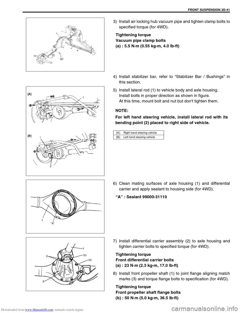
3) Install air locking hub vacuum pipe and tighten clamp bolts to
specified torque (for 4WD).
Tightening torque
Vacuum pipe clamp bolts
(a) : 5.5 N·m (0.55 kg-m, 4.0 lb-ft)
4) Install stabilizer bar, refer to “Stabilizer Bar / Bushings” in
this section.
5) Install lateral rod (1) to vehicle body and axle housing.
Install bolts in proper direction as shown in figure.
At this time, mount bolt and nut but don't tighten them.
6) Clean mating surfaces of axle housing (1) and differential
carrier and apply sealant to housing side (for 4WD).
“A” : Sealant 99000-31110
7) Install differential carrier assembly (2) to axle housing and
tighten carrier bolts to specified torque (for 4WD).
Tightening torque
Front differential carrier bolts
(a) : 23 N·m (2.3 kg-m, 17.0 lb-ft)
8) Install front propeller shaft (1) to joint flange aligning match
marks (3) and torque flange bolts to specification (for 4WD).
Tightening torque
Front propeller shaft flange bolts
(b) : 50 N·m (5.0 kg-m, 36.5 lb-ft)
NOTE:
For left hand steering vehicle, install lateral rod with its
bending point (2) placed to right side of vehicle.
[A] : Right hand steering vehicle
[B] : Left hand steering vehicle
Page 215 of 687
Downloaded from www.Manualslib.com manuals search engine 3D-42 FRONT SUSPENSION
9) Install right and left axle shafts to axle housing (for 4WD).
Install knuckle to axle housing (for 2WD).
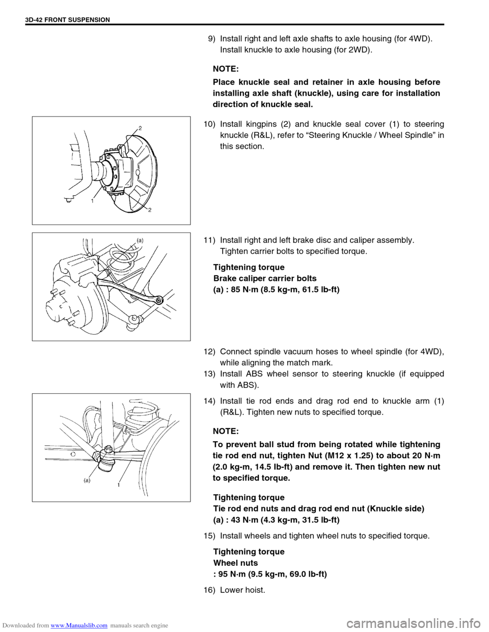
10) Install kingpins (2) and knuckle seal cover (1) to steering
knuckle (R&L), refer to “Steering Knuckle / Wheel Spindle” in
this section.
11) Install right and left brake disc and caliper assembly.
Tighten carrier bolts to specified torque.
Tightening torque
Brake caliper carrier bolts
(a) : 85 N·m (8.5 kg-m, 61.5 lb-ft)
12) Connect spindle vacuum hoses to wheel spindle (for 4WD),
while aligning the match mark.
13) Install ABS wheel sensor to steering knuckle (if equipped
with ABS).
14) Install tie rod ends and drag rod end to knuckle arm (1)
(R&L). Tighten new nuts to specified torque.
Tightening torque
Tie rod end nuts and drag rod end nut (Knuckle side)
(a) : 43 N·m (4.3 kg-m, 31.5 lb-ft)
15) Install wheels and tighten wheel nuts to specified torque.
Tightening torque
Wheel nuts
: 95 N·m (9.5 kg-m, 69.0 lb-ft)
16) Lower hoist.NOTE:
Place knuckle seal and retainer in axle housing before
installing axle shaft (knuckle), using care for installation
direction of knuckle seal.
NOTE:
To prevent ball stud from being rotated while tightening
tie rod end nut, tighten Nut (M12 x 1.25) to about 20 N·m
(2.0 kg-m, 14.5 Ib-ft) and remove it. Then tighten new nut
to specified torque.
Page 249 of 687
Downloaded from www.Manualslib.com manuals search engine 3F-6 WHEELS AND TIRES
Maintenance and Minor Adjustments
Wheel and Tire
Wheel repairs that use welding, heating, or peening are not approved. All damaged wheels should be replaced.
Studs
If a broken stud is found, see Section 3E (rear) or Section 3D (front) for Note and Replacement procedure.
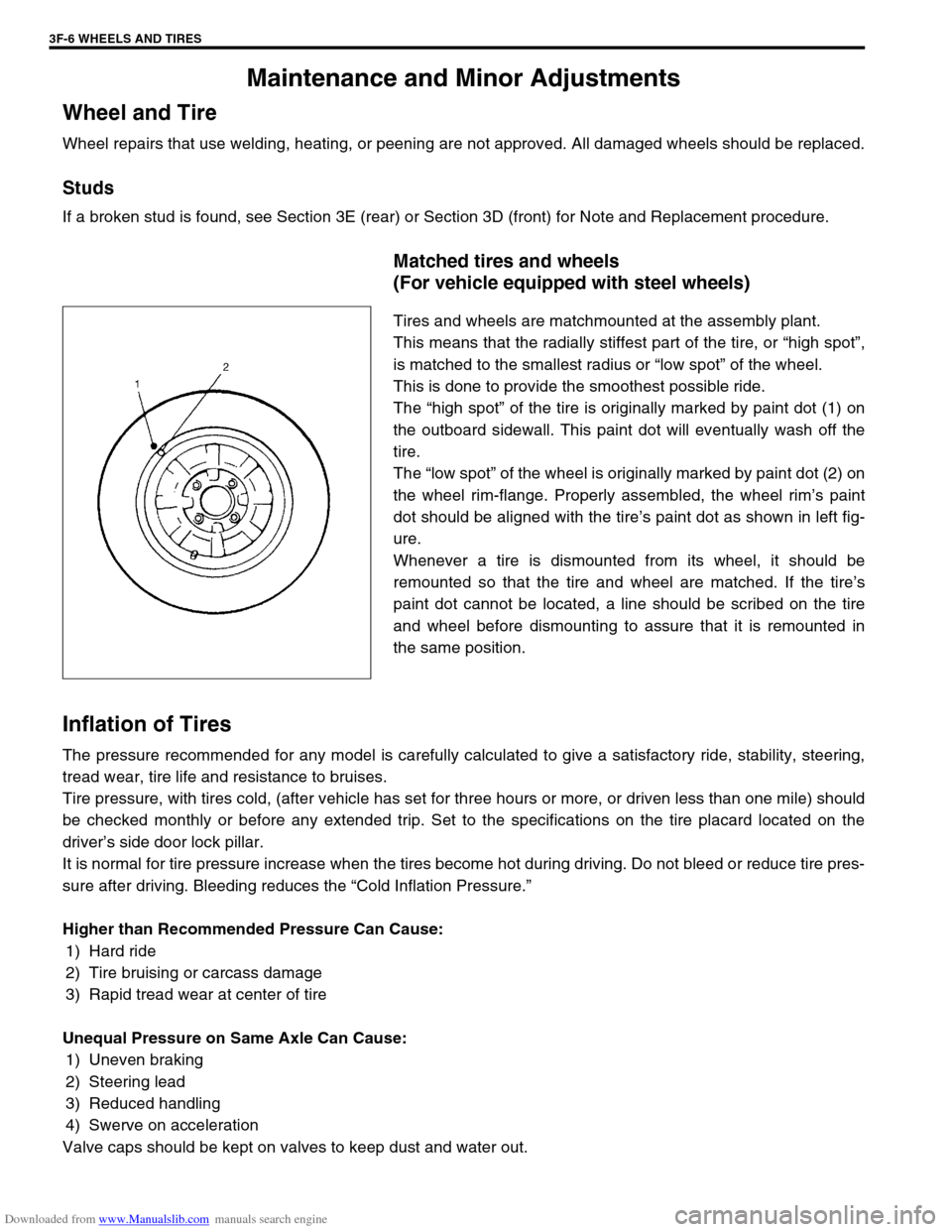
Matched tires and wheels
(For vehicle equipped with steel wheels)
Tires and wheels are matchmounted at the assembly plant.
This means that the radially stiffest part of the tire, or “high spot”,
is matched to the smallest radius or “low spot” of the wheel.
This is done to provide the smoothest possible ride.
The “high spot” of the tire is originally marked by paint dot (1) on
the outboard sidewall. This paint dot will eventually wash off the
tire.
The “low spot” of the wheel is originally marked by paint dot (2) on
the wheel rim-flange. Properly assembled, the wheel rim’s paint
dot should be aligned with the tire’s paint dot as shown in left fig-
ure.
Whenever a tire is dismounted from its wheel, it should be
remounted so that the tire and wheel are matched. If the tire’s
paint dot cannot be located, a line should be scribed on the tire
and wheel before dismounting to assure that it is remounted in
the same position.
Inflation of Tires
The pressure recommended for any model is carefully calculated to give a satisfactory ride, stability, steering,
tread wear, tire life and resistance to bruises.
Tire pressure, with tires cold, (after vehicle has set for three hours or more, or driven less than one mile) should
be checked monthly or before any extended trip. Set to the specifications on the tire placard located on the
driver’s side door lock pillar.
It is normal for tire pressure increase when the tires become hot during driving. Do not bleed or reduce tire pres-
sure after driving. Bleeding reduces the “Cold Inflation Pressure.”
Higher than Recommended Pressure Can Cause:
1) Hard ride
2) Tire bruising or carcass damage
3) Rapid tread wear at center of tire
Unequal Pressure on Same Axle Can Cause:
1) Uneven braking
2) Steering lead
3) Reduced handling
4) Swerve on acceleration
Valve caps should be kept on valves to keep dust and water out.
Page 288 of 687
Downloaded from www.Manualslib.com manuals search engine BRAKES 5-27
INSPECTION
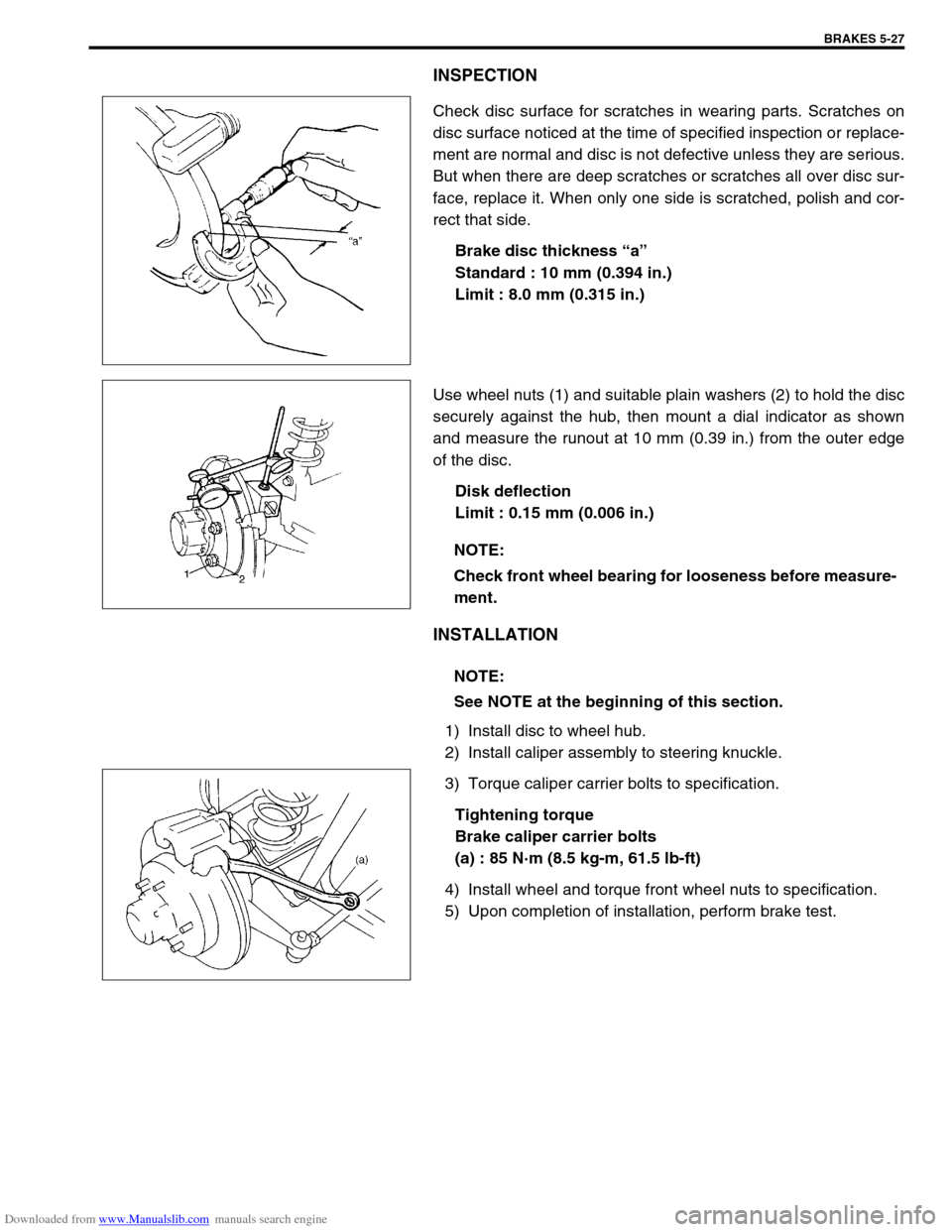
Check disc surface for scratches in wearing parts. Scratches on
disc surface noticed at the time of specified inspection or replace-
ment are normal and disc is not defective unless they are serious.
But when there are deep scratches or scratches all over disc sur-
face, replace it. When only one side is scratched, polish and cor-
rect that side.
Brake disc thickness “a”
Standard : 10 mm (0.394 in.)
Limit : 8.0 mm (0.315 in.)
Use wheel nuts (1) and suitable plain washers (2) to hold the disc
securely against the hub, then mount a dial indicator as shown
and measure the runout at 10 mm (0.39 in.) from the outer edge
of the disc.
Disk deflection
Limit : 0.15 mm (0.006 in.)
INSTALLATION
1) Install disc to wheel hub.
2) Install caliper assembly to steering knuckle.
3) Torque caliper carrier bolts to specification.
Tightening torque
Brake caliper carrier bolts
(a) : 85 N·m (8.5 kg-m, 61.5 lb-ft)
4) Install wheel and torque front wheel nuts to specification.
5) Upon completion of installation, perform brake test.
NOTE:
Check front wheel bearing for looseness before measure-
ment.
NOTE:
See NOTE at the beginning of this section.
Page 309 of 687
Downloaded from www.Manualslib.com manuals search engine 5-48 BRAKES
Brake Hose/Pipe
Front brake hose/pipe
For left-hand steering vehicle
[A] : For vehicle without ABS X : View X 5. Brake caliper 12. To front left brake caliper
[B] : For vehicle with ABS Y : View Y 6. 4 way joint 13. To rear brake
F : Front side Z : View Z 7. 5 way joint a-d: Clamp
R : Right side 1. E-ring 8. ABS hydraulic unit/control mod-
ule assemblyTightening torque
T : Top side 2. Flexible hose 9. P valve
V : View V 3. Hose washer 10. Hose bracket
W : View W 4. Hose bolt 11. To front right brake caliper
Page 319 of 687
Downloaded from www.Manualslib.com manuals search engine 5E-2 ANTILOCK BRAKE SYSTEM (ABS)
General Description
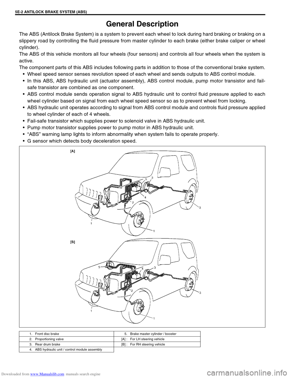
The ABS (Antilock Brake System) is a system to prevent each wheel to lock during hard braking or braking on a
slippery road by controlling the fluid pressure from master cylinder to each brake (either brake caliper or wheel
cylinder).
The ABS of this vehicle monitors all four wheels (four sensors) and controls all four wheels when the system is
active.
The component parts of this ABS includes following parts in addition to those of the conventional brake system.
Wheel speed sensor senses revolution speed of each wheel and sends outputs to ABS control module.
In this ABS, ABS hydraulic unit (actuator assembly), ABS control module, pump motor transistor and fail-
safe transistor are combined as one component.
ABS control module sends operation signal to ABS hydraulic unit to control fluid pressure applied to each
wheel cylinder based on signal from each wheel speed sensor so as to prevent wheel from locking.
ABS hydraulic unit operates according to signal from ABS control module and controls fluid pressure applied
to wheel cylinder of each of 4 wheels.
Fail-safe transistor which supplies power to solenoid valve in ABS hydraulic unit.
Pump motor transistor supplies power to pump motor in ABS hydraulic unit.
“ABS” warning lamp lights to inform abnormality when system fails to operate properly.
G sensor which detects body deceleration speed.
1. Front disc brake 5. Brake master cylinder / booster
2. Proportioning valve [A] : For LH steering vehicle
3. Rear drum brake [B] : For RH steering vehicle
4. ABS hydraulic unit / control module assembly
Page 321 of 687
Downloaded from www.Manualslib.com manuals search engine 5E-4 ANTILOCK BRAKE SYSTEM (ABS)
ABS Component Parts Location
1. Wheel speed sensor (Right front) 6. ABS hydraulic unit / control module assembly 11. Proportioning valve
2. Stop lamp switch 7. Monitor connector [A] : For LH steering vehicle
3.“ABS” warning lamp 8. Wheel speed sensor (Left front) [B] : For RH steering vehicle
4. Wheel speed sensor (Right rear) 9. Wheel speed sensor ring
5. Wheel speed sensor (Left rear) 10. G sensor
Page 554 of 687
Downloaded from www.Manualslib.com manuals search engine ENGINE MECHANICAL (M13 ENGINE) 6A1-73
Unit Repair Overhaul
Engine Assembly
REMOVAL
1) Relieve fuel pressure referring to “Fuel Pressure Relief Pro-
cedure” in Section 6.
2) Disconnect negative cable at battery.
3) Remove engine hood after disconnecting windshield washer
hose.
4) Remove A/C compressor and/or P/S pump belt (if
equipped).
5) Remove generator belt.
6) Drain engine oil.
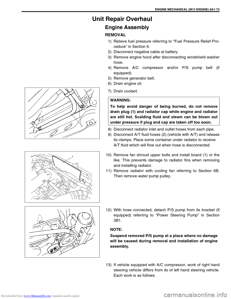
7) Drain coolant.
8) Disconnect radiator inlet and outlet hoses from each pipe.
9) Disconnect A/T fluid hoses (2) (vehicle with A/T) and release
its clamps. Place some container under radiator to receive
A/T fluid which will flow out when hose is disconnected.
10) Remove fan shroud upper bolts and install board (1) or the
like. This prevents damage to radiator fins when removing
and installing radiator.
11) Remove radiator with cooling fan referring to Section 6B.
Then remove water pump pulley.
12) With hose connected, detach P/S pump from its bracket (if
equipped) referring to “Power Steering Pump” in Section
3B1.
13) If vehicle equipped with A/C compressor, work of right hand
steering vehicle differs from its of left hand steering vehicle.
Each work is as follows. WARNING:
To help avoid danger of being burned, do not remove
drain plug (1) and radiator cap while engine and radiator
are still hot. Scalding fluid and steam can be blown out
under pressure if plug and cap are taken off too soon.
NOTE:
Suspend removed P/S pump at a place where no damage
will be caused during removal and installation of engine
assembly.