2005 SUZUKI JIMNY power steering fluid
[x] Cancel search: power steering fluidPage 152 of 687

Downloaded from www.Manualslib.com manuals search engine POWER STEERING (P/S) SYSTEM (If equipped) 3B1-21
Tightening Torque Specifications
Required Service Materials
Special Tools
Fastening partTightening torque
Nm kg-m lb-ft
Tension pulley bolt 25 2.5 18.0
Oil pump mounting bolt 25 2.5 18.5
Oil pump high pressure union bolt 60 6.0 43.5
Oil pump cover bolts 28 2.8 20.0
Pressure switch 28 2.8 20.0
Suction connector bolt 12 1.2 8.5
Power steering gear box mounting bolt
and nuts80 8.0 58.0
Gear box high pressure union bolt 35 3.5 25.5
Pitman arm mounting nut 135 13.5 98.0
Steering shaft joint bolt 25 2.5 18.5
Plug 60 6.0 43.5
MaterialRecommended SUZUKI product
(Part Number)Use
Power steering
fluidAn equivalent of DEXRON
®-II,
DEXRON
®-IIE or DEXRON®-III.To fill P/S fluid reservoir
Parts lubrication when installing
Lithium greaseSUPER GREASE (A)
(99000-25010)Oil seal lip of P/S pump pulley shaft
09915-77411 09915-77420 09944-18211 09945-35010
Oil pressure gauge Oil pressure gauge
attachment & hose setTorque check socket Air bleeding hose set
Page 319 of 687
Downloaded from www.Manualslib.com manuals search engine 5E-2 ANTILOCK BRAKE SYSTEM (ABS)
General Description
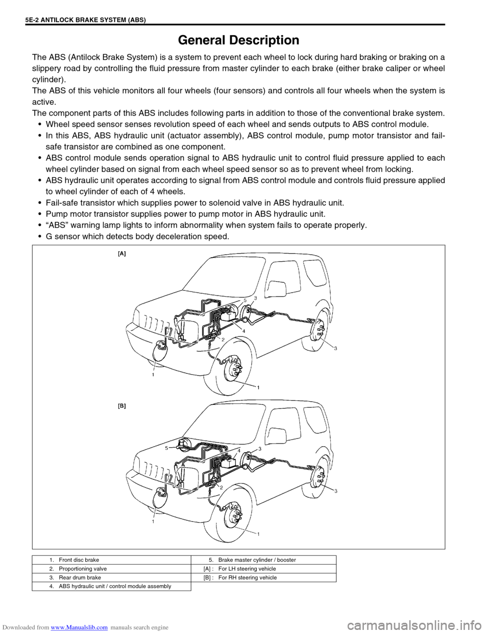
The ABS (Antilock Brake System) is a system to prevent each wheel to lock during hard braking or braking on a
slippery road by controlling the fluid pressure from master cylinder to each brake (either brake caliper or wheel
cylinder).
The ABS of this vehicle monitors all four wheels (four sensors) and controls all four wheels when the system is
active.
The component parts of this ABS includes following parts in addition to those of the conventional brake system.
Wheel speed sensor senses revolution speed of each wheel and sends outputs to ABS control module.
In this ABS, ABS hydraulic unit (actuator assembly), ABS control module, pump motor transistor and fail-
safe transistor are combined as one component.
ABS control module sends operation signal to ABS hydraulic unit to control fluid pressure applied to each
wheel cylinder based on signal from each wheel speed sensor so as to prevent wheel from locking.
ABS hydraulic unit operates according to signal from ABS control module and controls fluid pressure applied
to wheel cylinder of each of 4 wheels.
Fail-safe transistor which supplies power to solenoid valve in ABS hydraulic unit.
Pump motor transistor supplies power to pump motor in ABS hydraulic unit.
“ABS” warning lamp lights to inform abnormality when system fails to operate properly.
G sensor which detects body deceleration speed.
1. Front disc brake 5. Brake master cylinder / booster
2. Proportioning valve [A] : For LH steering vehicle
3. Rear drum brake [B] : For RH steering vehicle
4. ABS hydraulic unit / control module assembly
Page 510 of 687
Downloaded from www.Manualslib.com manuals search engine ENGINE MECHANICAL (M13 ENGINE) 6A1-29
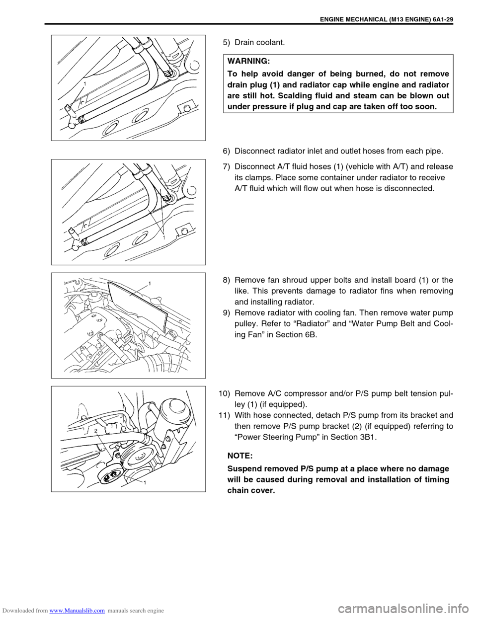
5) Drain coolant.
6) Disconnect radiator inlet and outlet hoses from each pipe.
7) Disconnect A/T fluid hoses (1) (vehicle with A/T) and release
its clamps. Place some container under radiator to receive
A/T fluid which will flow out when hose is disconnected.
8) Remove fan shroud upper bolts and install board (1) or the
like. This prevents damage to radiator fins when removing
and installing radiator.
9) Remove radiator with cooling fan. Then remove water pump
pulley. Refer to “Radiator” and “Water Pump Belt and Cool-
ing Fan” in Section 6B.
10) Remove A/C compressor and/or P/S pump belt tension pul-
ley (1) (if equipped).
11) With hose connected, detach P/S pump from its bracket and
then remove P/S pump bracket (2) (if equipped) referring to
“Power Steering Pump” in Section 3B1. WARNING:
To help avoid danger of being burned, do not remove
drain plug (1) and radiator cap while engine and radiator
are still hot. Scalding fluid and steam can be blown out
under pressure if plug and cap are taken off too soon.
NOTE:
Suspend removed P/S pump at a place where no damage
will be caused during removal and installation of timing
chain cover.
Page 513 of 687
Downloaded from www.Manualslib.com manuals search engine 6A1-32 ENGINE MECHANICAL (M13 ENGINE)
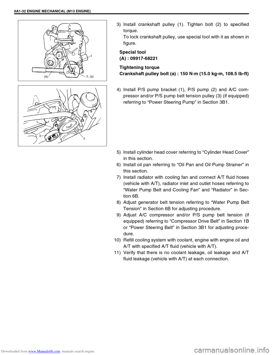
3) Install crankshaft pulley (1). Tighten bolt (2) to specified
torque.
To lock crankshaft pulley, use special tool with it as shown in
figure.
Special tool
(A) : 09917-68221
Tightening torque
Crankshaft pulley bolt (a) : 150 N·m (15.0 kg-m, 108.5 lb-ft)
4) Install P/S pump bracket (1), P/S pump (2) and A/C com-
pressor and/or P/S pump belt tension pulley (3) (if equipped)
referring to “Power Steering Pump” in Section 3B1.
5) Install cylinder head cover referring to “Cylinder Head Cover”
in this section.
6) Install oil pan referring to “Oil Pan and Oil Pump Strainer” in
this section.
7) Install radiator with cooling fan and connect A/T fluid hoses
(vehicle with A/T), radiator inlet and outlet hoses referring to
“Water Pump Belt and Cooling Fan” and “Radiator” in Sec-
tion 6B.
8) Adjust generator belt tension referring to “Water Pump Belt
Tension” in Section 6B for adjusting procedure.
9) Adjust A/C compressor and/or P/S pump belt tension (if
equipped) referring to “Compressor Drive Belt” in Section 1B
or “Power Steering Belt” in Section 3B1 for adjusting proce-
dure.
10) Refill cooling system with coolant, engine with engine oil and
A/T with specified A/T fluid (vehicle with A/T).
11) Verify that there is no coolant leakage, oil leakage and A/T
fluid leakage (vehicle with A/T) at each connection.
Page 528 of 687

Downloaded from www.Manualslib.com manuals search engine ENGINE MECHANICAL (M13 ENGINE) 6A1-47
5) After applying engine oil to housing bolts, tighten them tem-
porarily first. Then tighten them by the following numerical
order in figure. Tighten a little at a time and evenly among
bolts and repeat tightening sequence two or three times
before they are tightened to specified torque.
Tightening torque
Camshaft housing bolts (a) : 11 N·m (1.1 kg-m, 8.0 lb-ft)
6) Install timing chain with crankshaft sprocket referring to
“Timing Chain and Chain Tensioner” in this section.
7) Install timing chain cover referring to “Timing Chain Cover” in
this section.
8) Check valve lashes referring to “Valve Lash” in this section.
9) Install cylinder head cover and oil pan referring to “Cylinder
Head Cover” and “Oil Pan and Oil Pump Strainer” in this sec-
tion.
10) Install radiator with cooling fan and connect A/T fluid hoses
(vehicle with A/T), radiator inlet and outlet hoses referring to
“Water Pump Belt and Cooling Fan” and “Radiator” in Sec-
tion 6B.
11) Adjust generator belt tension referring to “Water Pump Belt
Tension” in Section 6B.
12) Adjust A/C compressor and/or P/S pump belt tension (if
equipped) referring to “Compressor Drive Belt” in Section 1B
or “Power Steering Belt” in Section 3B1.
13) Refill cooling system with coolant, engine with engine oil and
A/T with specified A/T fluid (vehicle with A/T).
14) Verify that there is no coolant leakage, oil leakage and A/T
fluid leakage (vehicle with A/T) at each connection.
Page 542 of 687

Downloaded from www.Manualslib.com manuals search engine ENGINE MECHANICAL (M13 ENGINE) 6A1-61
6) Install exhaust manifold stiffener and exhaust pipe referring
to “Exhaust Manifold” in this section.
7) Install camshafts, timing chain and chain cover referring to
“Camshaft, Tappet and Shim”, “Timing Chain and Chain
Tensioner” and “Timing Chain Cover” in this section.
8) Install cylinder head cover and oil pan referring to “Cylinder
Head Cover” and “Oil Pan and Oil Pump Strainer” in this sec-
tion.
9) Install intake manifold stiffener and connect each hoses and
electric lead wires securely.
10) Install air cleaner outlet hoses.
11) Install radiator with cooling fan and connect A/T fluid hoses
(vehicle with A/T), radiator inlet and outlet hoses referring to
“Water Pump Belt and Cooling Fan” and “Radiator” in Sec-
tion 6B.
12) Adjust generator belt tension referring to “Water Pump Belt
Tension” in Section 6B.
13) Adjust A/C compressor and/or P/S pump belt tension (if
equipped) referring to “Compressor Drive Belt” in Section 1B
or “Power Steering Belt” in Section 3B1.
14) Adjust accelerator cable play referring to “Accelerator Cable
Adjustment” in Section 6E.
15) Check to ensure that all removed parts are back in place.
Reinstall any necessary parts which have not been rein-
stalled.
16) Refill cooling system with coolant, engine with engine oil and
A/T with specified A/T fluid (vehicle with A/T).
17) Connect negative cable at battery.
18) Verify that there is no fuel leakage, coolant leakage, oil leak-
age, A/T fluid leakage (vehicle with A/T) and exhaust gas
leakage at each connection.
Page 552 of 687
Downloaded from www.Manualslib.com manuals search engine ENGINE MECHANICAL (M13 ENGINE) 6A1-71
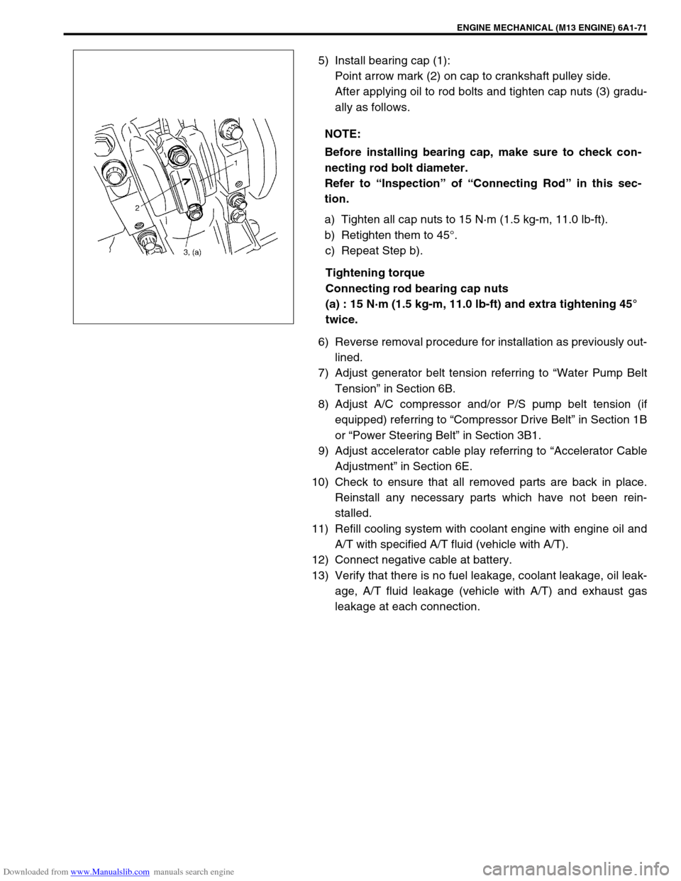
5) Install bearing cap (1):
Point arrow mark (2) on cap to crankshaft pulley side.
After applying oil to rod bolts and tighten cap nuts (3) gradu-
ally as follows.
a) Tighten all cap nuts to 15 N·m (1.5 kg-m, 11.0 lb-ft).
b) Retighten them to 45°.
c) Repeat Step b).
Tightening torque
Connecting rod bearing cap nuts
(a) : 15 N·m (1.5 kg-m, 11.0 lb-ft) and extra tightening 45°
twice.
6) Reverse removal procedure for installation as previously out-
lined.
7) Adjust generator belt tension referring to “Water Pump Belt
Tension” in Section 6B.
8) Adjust A/C compressor and/or P/S pump belt tension (if
equipped) referring to “Compressor Drive Belt” in Section 1B
or “Power Steering Belt” in Section 3B1.
9) Adjust accelerator cable play referring to “Accelerator Cable
Adjustment” in Section 6E.
10) Check to ensure that all removed parts are back in place.
Reinstall any necessary parts which have not been rein-
stalled.
11) Refill cooling system with coolant engine with engine oil and
A/T with specified A/T fluid (vehicle with A/T).
12) Connect negative cable at battery.
13) Verify that there is no fuel leakage, coolant leakage, oil leak-
age, A/T fluid leakage (vehicle with A/T) and exhaust gas
leakage at each connection. NOTE:
Before installing bearing cap, make sure to check con-
necting rod bolt diameter.
Refer to “Inspection” of “Connecting Rod” in this sec-
tion.
Page 554 of 687
Downloaded from www.Manualslib.com manuals search engine ENGINE MECHANICAL (M13 ENGINE) 6A1-73
Unit Repair Overhaul
Engine Assembly
REMOVAL
1) Relieve fuel pressure referring to “Fuel Pressure Relief Pro-
cedure” in Section 6.
2) Disconnect negative cable at battery.
3) Remove engine hood after disconnecting windshield washer
hose.
4) Remove A/C compressor and/or P/S pump belt (if
equipped).
5) Remove generator belt.
6) Drain engine oil.
7) Drain coolant.
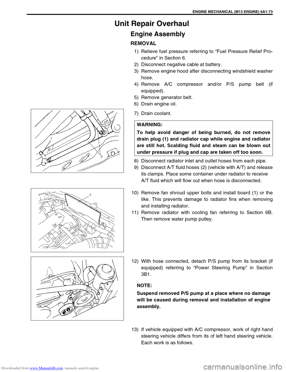
8) Disconnect radiator inlet and outlet hoses from each pipe.
9) Disconnect A/T fluid hoses (2) (vehicle with A/T) and release
its clamps. Place some container under radiator to receive
A/T fluid which will flow out when hose is disconnected.
10) Remove fan shroud upper bolts and install board (1) or the
like. This prevents damage to radiator fins when removing
and installing radiator.
11) Remove radiator with cooling fan referring to Section 6B.
Then remove water pump pulley.
12) With hose connected, detach P/S pump from its bracket (if
equipped) referring to “Power Steering Pump” in Section
3B1.
13) If vehicle equipped with A/C compressor, work of right hand
steering vehicle differs from its of left hand steering vehicle.
Each work is as follows. WARNING:
To help avoid danger of being burned, do not remove
drain plug (1) and radiator cap while engine and radiator
are still hot. Scalding fluid and steam can be blown out
under pressure if plug and cap are taken off too soon.
NOTE:
Suspend removed P/S pump at a place where no damage
will be caused during removal and installation of engine
assembly.