Page 281 of 687
Downloaded from www.Manualslib.com manuals search engine 5-20 BRAKES
Brake pad
REMOVAL
1) Hoist vehicle and remove wheel.
2) Remove caliper pin bolts (2).
3) Remove caliper (1) from caliper carrier.
4) Remove pads (3).
INSPECTION
Check pad lining for wear. When wear exceeds limit, replace with
new one.
Brake pad thickness (lining + pad rim)
Standard : 15 mm (0.59 in.)
Limit : 7 mm (0.28 in.)
1. Caliper
3. Disc
NOTE:
Hang removed caliper (1) with a wire hook (2) or the like
so as to prevent brake hose from bending and twisting
excessively or being pulled.
Don’t operate brake pedal with pads (3) removed.
CAUTION:
Never polish pad lining with sandpaper. If lining is pol-
ished with sandpaper, hard particles of sandpaper will be
deposited in lining and may damage disc. When pad lin-
ing requires correction, replace it with a new one.
NOTE:
When pads are removed, visually inspect caliper for
brake fluid leak. Correct leaky point, if any.
Page 287 of 687
Downloaded from www.Manualslib.com manuals search engine 5-26 BRAKES
3) Install brake flexible hose (4) as shown and torque hose
mounting bolt (3) to specification.
Tightening torque
Front brake flexible hose bolt
(a) : 23 N·m (2.3 kg-m, 17.0 lb-ft)
4) Install wheel and torque wheel nuts to specification.
5) After completing installation, fill reservoir with brake fluid and
bleed brake system. Perform brake test and check each
installed part for oil leakage.
Brake Disc
REMOVAL
1) Hoist vehicle and remove wheel.
2) Remove caliper assembly by loosening carrier bolts (2 pcs).
3) Pull brake disc off by using 8 mm bolts (1) (2 pcs).
1. Brake caliper
2. Washer
CAUTION:
During removal, be careful not to damage brake flexible
hose and not to depress brake pedal.
Page 289 of 687
Downloaded from www.Manualslib.com manuals search engine 5-28 BRAKES
CHECK FOR FRONT BRAKE AFTER INSTALLATION
Mount tires and make certain that they rotate smoothly, with a
force of less than 3.0 kg (6.6 Ib).
If tire rotation is heavy, check the following:
Piston, piston seal and cylinder slide bush of caliper for
installation.
Wheel bearings for breakage.
Disc for flatness (Improper flatness brings disc into contact
with lining during rotation and makes rotation heavy).
To check this, measure disc deflection.NOTE:
For above check the following must be observed.
Jack up front wheels, both right and left, off the
ground.
Shift transfer shift lever to 2H (rear wheel) position (if
equipped) and start engine for a few seconds then
stop.
Side figure shows outer periphery of tire.
Be careful not to depress brake pedal when checking
tire for rotation.
1. String
2. Spring measure
Page 292 of 687

Downloaded from www.Manualslib.com manuals search engine BRAKES 5-31
Brake Shoe
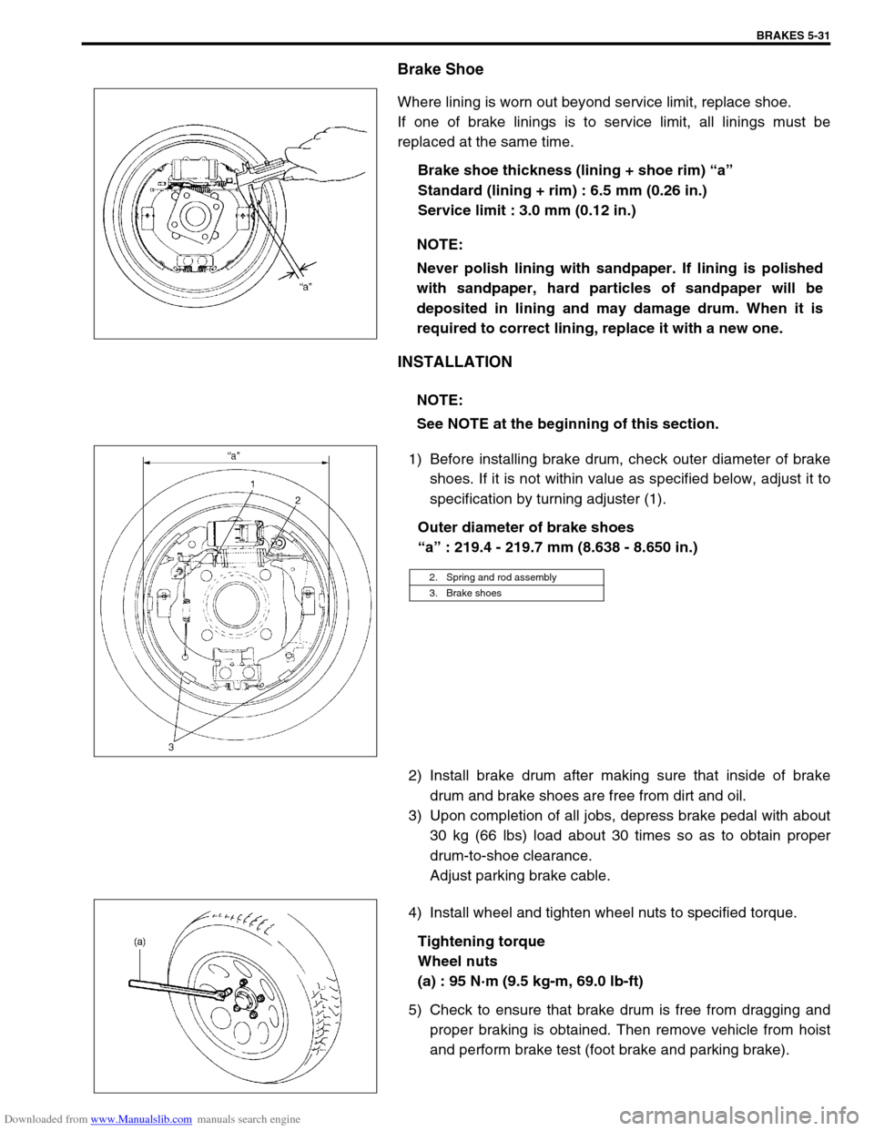
Where lining is worn out beyond service limit, replace shoe.
If one of brake linings is to service limit, all linings must be
replaced at the same time.
Brake shoe thickness (lining + shoe rim) “a”
Standard (lining + rim) : 6.5 mm (0.26 in.)
Service limit : 3.0 mm (0.12 in.)
INSTALLATION
1) Before installing brake drum, check outer diameter of brake
shoes. If it is not within value as specified below, adjust it to
specification by turning adjuster (1).
Outer diameter of brake shoes
“a” : 219.4 - 219.7 mm (8.638 - 8.650 in.)
2) Install brake drum after making sure that inside of brake
drum and brake shoes are free from dirt and oil.
3) Upon completion of all jobs, depress brake pedal with about
30 kg (66 lbs) load about 30 times so as to obtain proper
drum-to-shoe clearance.
Adjust parking brake cable.
4) Install wheel and tighten wheel nuts to specified torque.
Tightening torque
Wheel nuts
(a) : 95 N·m (9.5 kg-m, 69.0 lb-ft)
5) Check to ensure that brake drum is free from dragging and
proper braking is obtained. Then remove vehicle from hoist
and perform brake test (foot brake and parking brake). NOTE:
Never polish lining with sandpaper. If lining is polished
with sandpaper, hard particles of sandpaper will be
deposited in lining and may damage drum. When it is
required to correct lining, replace it with a new one.
NOTE:
See NOTE at the beginning of this section.
2. Spring and rod assembly
3. Brake shoes
Page 299 of 687

Downloaded from www.Manualslib.com manuals search engine 5-38 BRAKES
INSTALLATION
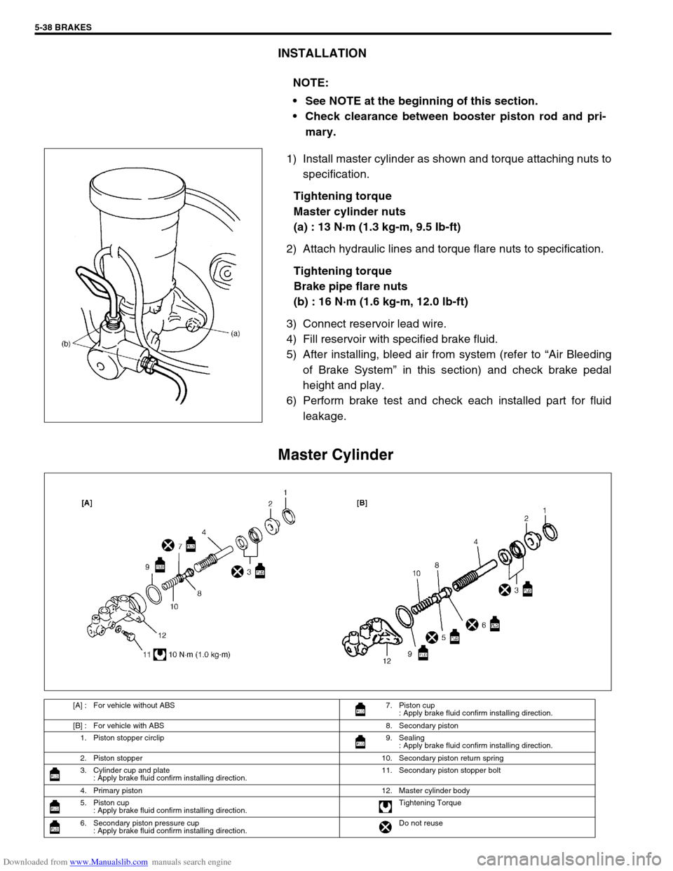
1) Install master cylinder as shown and torque attaching nuts to
specification.
Tightening torque
Master cylinder nuts
(a) : 13 N·m (1.3 kg-m, 9.5 Ib-ft)
2) Attach hydraulic lines and torque flare nuts to specification.
Tightening torque
Brake pipe flare nuts
(b) : 16 N·m (1.6 kg-m, 12.0 lb-ft)
3) Connect reservoir lead wire.
4) Fill reservoir with specified brake fluid.
5) After installing, bleed air from system (refer to “Air Bleeding
of Brake System” in this section) and check brake pedal
height and play.
6) Perform brake test and check each installed part for fluid
leakage.
Master Cylinder
NOTE:
See NOTE at the beginning of this section.
Check clearance between booster piston rod and pri-
mary.
[A] : For vehicle without ABS 7. Piston cup
: Apply brake fluid confirm installing direction.
[B] : For vehicle with ABS 8. Secondary piston
1. Piston stopper circlip 9. Sealing
: Apply brake fluid confirm installing direction.
2. Piston stopper 10. Secondary piston return spring
3. Cylinder cup and plate
: Apply brake fluid confirm installing direction.11. Secondary piston stopper bolt
4. Primary piston 12. Master cylinder body
5. Piston cup
: Apply brake fluid confirm installing direction.Tightening Torque
6. Secondary piston pressure cup
: Apply brake fluid confirm installing direction.Do not reuse
Page 307 of 687

Downloaded from www.Manualslib.com manuals search engine 5-46 BRAKES
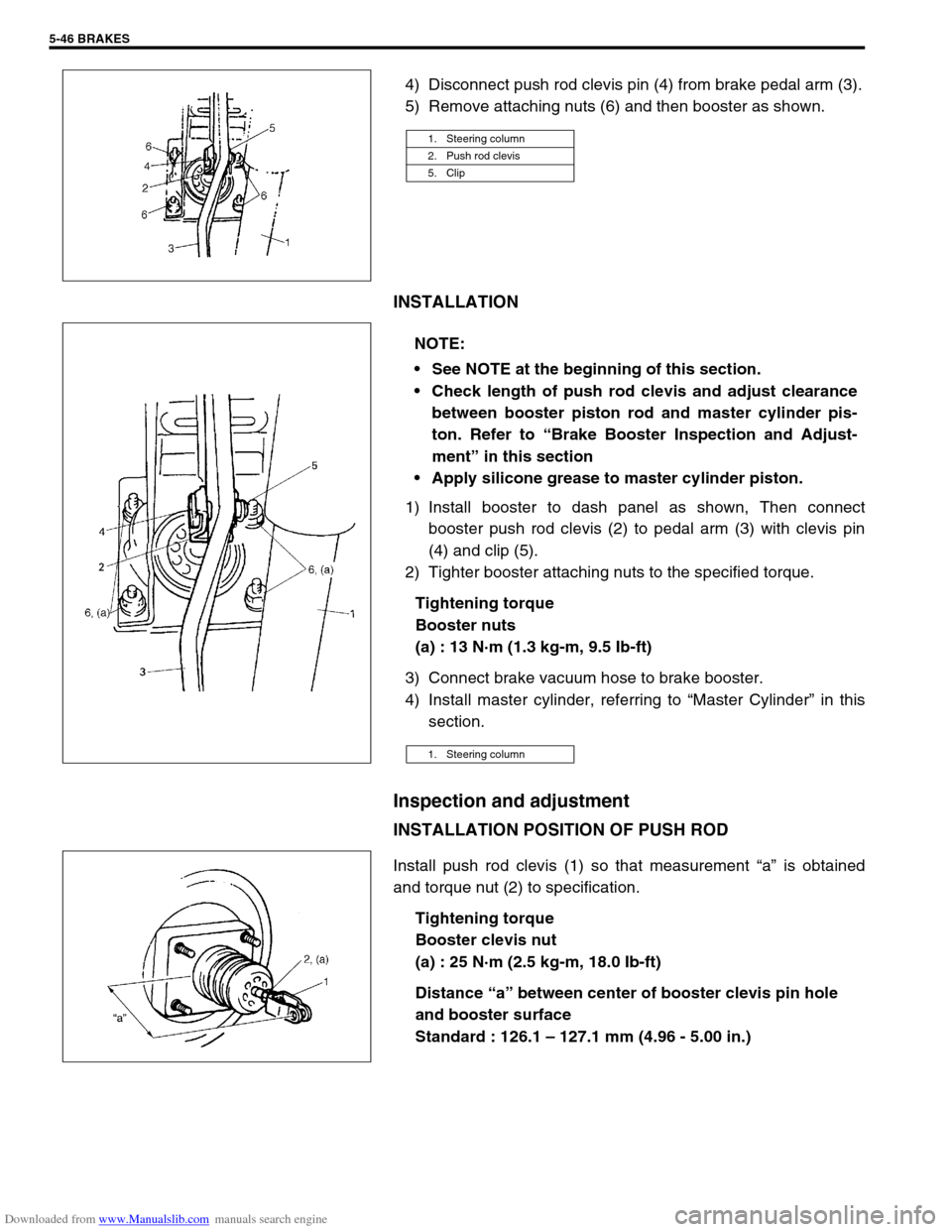
4) Disconnect push rod clevis pin (4) from brake pedal arm (3).
5) Remove attaching nuts (6) and then booster as shown.
INSTALLATION
1) Install booster to dash panel as shown, Then connect
booster push rod clevis (2) to pedal arm (3) with clevis pin
(4) and clip (5).
2) Tighter booster attaching nuts to the specified torque.
Tightening torque
Booster nuts
(a) : 13 N·m (1.3 kg-m, 9.5 Ib-ft)
3) Connect brake vacuum hose to brake booster.
4) Install master cylinder, referring to “Master Cylinder” in this
section.
Inspection and adjustment
INSTALLATION POSITION OF PUSH ROD
Install push rod clevis (1) so that measurement “a” is obtained
and torque nut (2) to specification.
Tightening torque
Booster clevis nut
(a) : 25 N·m (2.5 kg-m, 18.0 Ib-ft)
Distance “a” between center of booster clevis pin hole
and booster surface
Standard : 126.1 – 127.1 mm (4.96 - 5.00 in.)
1. Steering column
2. Push rod clevis
5. Clip
NOTE:
See NOTE at the beginning of this section.
Check length of push rod clevis and adjust clearance
between booster piston rod and master cylinder pis-
ton. Refer to “Brake Booster Inspection and Adjust-
ment” in this section
Apply silicone grease to master cylinder piston.
1. Steering column
Page 333 of 687

Downloaded from www.Manualslib.com manuals search engine 5E-16 ANTILOCK BRAKE SYSTEM (ABS)
Table – C “ABS” Warning Lamp Circuit Check – Lamp Flashes Continuously
While Ignition Switch is ON
CIRCUIT DESCRIPTION
When the diag. switch terminal is shorted or connected to the ground with the ignition switch ON, the diag. trou-
ble code (DTC) is indicated by flashing of the “ABS” warning lamp only in following cases.
Normal DTC (12) is indicated if no malfunction DTC is detected in the ABS.
A history malfunction DTC is indicated by flashing of the lamp if a current malfunction DTC is not detected at
that point although a history malfunction DTC is stored in memory.
INSPECTION
1.“ABS” warning lamp in combination meter 3-1. Diag. switch terminal 5. Pedal bracket
2. ABS hydraulic unit / control module assembly 3-2. Diag. ground terminal
3. Monitor connector 4. Service wire
Step Action Yes No
1 Is diag. switch terminal connected to ground via
service wire?Go to step 3. Go to step 2.
2 1) Ignition switch ON.
2) Measure voltage between diag. switch ter-
minal and ground.
Is it 10 – 14 V?Substitute a known-good
ABS hydraulic unit / con-
trol module assembly and
recheck.“P/B” wire circuit shorted
to ground.
3 1) Ignition switch ON.
2) Does flashing of ABS warning lamp indicate
DTC (DTC 12 or history DTC)?Go to step 7 of “ABS diag-
nostic flow table” in this
section.Substitute a known-good
ABS hydraulic unit / con-
trol module assembly and
recheck.
Page 337 of 687
Downloaded from www.Manualslib.com manuals search engine 5E-20 ANTILOCK BRAKE SYSTEM (ABS)
DTC C1016 (DTC 16) – Stop Lamp Circuit
DESCRIPTION
The ABS control module monitors the voltage at the stop lamp while the ignition switch is ON. When the voltage
is without the specified range at terminal “A2”, a DTC will be set.
INSPECTION
1. Main fuse 4. IG fuse 7. ABS hydraulic unit / control module assembly
2. Ignition switch 5. Stop lamp switch 8. ABS hydraulic unit / control module connector of harness
3. Tail stop fuse 6. Stop lamp
Step Action Yes No
1 1) Turn IG switch OFF.
2) Disconnect connectors from ABS hydraulic
unit / control module assembly.
3) Depress the brake pedal.
4) Measure the voltage between the stop lamp
terminal “A2” and body ground.
Is it 10 – 14 V?Check for proper connection to
ABS control module at terminal
“A2”. If OK, substitute a known-
good ABS control module and
recheck.“G/W” circuit open.