2005 SUZUKI JIMNY transmission oil
[x] Cancel search: transmission oilPage 612 of 687
Downloaded from www.Manualslib.com manuals search engine ENGINE AND EMISSION CONTROL SYSTEM 6E-7
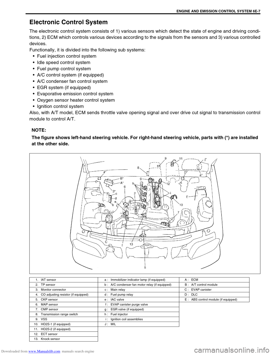
Electronic Control System
The electronic control system consists of 1) various sensors which detect the state of engine and driving condi-
tions, 2) ECM which controls various devices according to the signals from the sensors and 3) various controlled
devices.
Functionally, it is divided into the following sub systems:
Fuel injection control system
Idle speed control system
Fuel pump control system
A/C control system (if equipped)
A/C condenser fan control system
EGR system (if equipped)
Evaporative emission control system
Oxygen sensor heater control system
Ignition control system
Also, with A/T model, ECM sends throttle valve opening signal and over drive cut signal to transmission control
module to control A/T.
NOTE:
The figure shows left-hand steering vehicle. For right-hand steering vehicle, parts with (*) are installed
at the other side.
1. IAT sensor a : Immobilizer indicator lamp (if equipped) A : ECM
2. TP sensor b : A/C condenser fan motor relay (if equipped) B : A/T control module
3. Monitor connector c : Main relay C : EVAP canister
4. CO adjusting resistor (if equipped) d : Fuel pump relay D : DLC
5. CKP sensor e : IAC valve E : ABS control module (if equipped)
6. MAP sensor f : EVAP canister purge valve
7. CMP sensor g : EGR valve (if equipped)
8. Transmission range switch h : Fuel injector
9. VSS i : Ignition coil assemblies
10. HO2S-1 (if equipped) J : MIL
11. HO2S-2 (if equipped)
12. ECT sensor
13. Knock sensor
Page 613 of 687

Downloaded from www.Manualslib.com manuals search engine 6E-8 ENGINE AND EMISSION CONTROL SYSTEM
Engine & emission control input / output table
INPUTOUTPUT
ELECTRIC CONTROL DEVICE
DIAGNOSIS SWITCH TERMINAL
(VEHICLE WITHOUT IMMOBILIZER INDICATOR LAMP)
BAROMETRIC PRESSURE SENSOR
(VEHICLE WITH IMMOBILIZER INDICATOR LAMP)
STOP LAMP SWITCH
STARTER SWITCH
IGNITION SWITCH
LIGHTING SWITCH
REAR DEFOGGER SWITCH (IF EQUIPPED)
BLOWER SWITCH
A/C SWITCH (IF EQUIPPED)
A/C EVAPORATOR TEMP. SENSOR (IF EQUIPPED)
VSS
HEATED OXYGEN SENSOR-1 (IF EQUIPPED)
HEATED OXYGEN SENSOR-2
(IF EQUIPPED)For detecting deterioration of
three way catalytic converter
IAT SENSOR
ECT SENSOR
TP SENSOR
MAP SENSOR
CMP SENSOR
CKP SENSOR
TEST SWITCH TERMINAL
(VEHICLE WITHOUT IMMOBILIZER INDICATOR LAMP)
KNOCK SENSOR
FUEL PUMP RELAY
FUEL INJECTOR
HO2S HEATER
IAC VALVE
IGNITION COIL WITH IGNITER
EGR VALVE (IF EQUIPPED)
EVAP CANISTER PURGE VALVE
A/C COMPRESSOR CLUTCH
MIL
MAIN RELAY
TRANSMISSION CONTROL MODULE SIGNAL FROM SENSOR, SWITCH AND CONTROL MODULEA/C CONDENSER FAN RELAY
Page 615 of 687

Downloaded from www.Manualslib.com manuals search engine 6E-10 ENGINE AND EMISSION CONTROL SYSTEM
1. CKP sensor 20. Power steering pressure switch
(if equipped)39. Ignition coil assembly (for No.1 and No.4 spark plugs)
2. CMP sensor 21. A/C switch 40. Ignition coil assembly (for No.2 and No.3 spark plugs)
3. VSS 22. A/C refrigerant pressure switch
(if equipped)41. Stop lamp switch
4. MAP sensor 23. Immobilizer control module (if equipped) 42. Stop lamp
5. Knock sensor 24. Data link connector 43. Lighting switch
6. TP sensor 25. Injector No.1 44. Position lamp
7. ECT sensor 26. Injector No.2 45. Rear defogger switch (if equipped)
8. IAT sensor 27. Injector No.3 46. Rear defogger (if equipped)
9. Heated oxygen sensor-1 (if equipped) 28. Injector No.4 47. A/C compressor clutch (if equipped)
10. Heated oxygen sensor-2 (if equipped) 29. IAC valve 48. Ignition switch
11. A/C evaporator temp. sensor (if equipped) 30. EVAP canister purge valve 49. Main relay
12. Speedometer 31. Fuel pump relay 50. CO adjusting register (if equipped)
13. Fuel level sensor 32. Fuel pump 51. Starting motor
14. TCM (A/T) 33. A/C condenser fan relay (if equipped) 52. 4WD controller (4WD)
15. Transmission range switch (A/T) 34. A/C condenser fan motor (if equipped) 53. ABS control module (if equipped)
16. Shift lock solenoid (A/T, if equipped) 35. EGR valve (if equipped) 54. Engine ground
17. Backup lamp 36. Malfunction indicator lamp 55. Body ground
18. Heater fan motor 37. Immobilizer indicator lamp (if equipped)
19. Heater fan switch 38. Monitor connector (vehicle without immo-
bilizer indicator lamp)
Page 617 of 687

Downloaded from www.Manualslib.com manuals search engine 6E-12 ENGINE AND EMISSION CONTROL SYSTEM
1. CKP sensor 20. Power steering pressure switch
(if equipped)39. Ignition coil assembly (for No.1 and No.4 spark plugs)
2. CMP sensor 21. A/C switch 40. Ignition coil assembly (for No.2 and No.3 spark plugs)
3. VSS 22. A/C refrigerant pressure switch
(if equipped)41. Stop lamp switch
4. MAP sensor 23. Immobilizer control module (if equipped) 42. Stop lamp
5. Knock sensor 24. Data link connector 43. Lighting switch
6. TP sensor 25. Injector No.1 44. Position lamp
7. ECT sensor 26. Injector No.2 45. Rear defogger switch (if equipped)
8. IAT sensor 27. Injector No.3 46. Rear defogger (if equipped)
9. Heated oxygen sensor-1 (if equipped) 28. Injector No.4 47. A/C compressor clutch (if equipped)
10. Heated oxygen sensor-2 (if equipped) 29. IAC valve 48. Ignition switch
11. A/C evaporator temp. sensor (if equipped) 30. EVAP canister purge valve 49. Main relay
12. Speedometer 31. Fuel pump relay 50. CO adjusting register (if equipped)
13. Fuel level sensor 32. Fuel pump 51. Starting motor
14. TCM (A/T) 33. A/C condenser fan relay (if equipped) 52. 4WD controller (4WD)
15. Transmission range switch (A/T) 34. A/C condenser fan motor (if equipped) 53. ABS control module (if equipped)
16. Shift lock solenoid (A/T, if equipped) 35. EGR valve (if equipped) 54. Engine ground
17. Backup lamp 36. Malfunction indicator lamp 55. Body ground
18. Heater fan motor 37. Immobilizer indicator lamp (if equipped)
19. Heater fan switch 38. Monitor connector (vehicle without immo-
bilizer indicator lamp)
Page 651 of 687
Downloaded from www.Manualslib.com manuals search engine 6F-2 IGNITION SYSTEM (ELECTRONIC IGNITION SYSTEM)
General Description
The ignition system is an electronic (distributorless) ignition system. It consists of the parts as described below
and has an electronic ignition control system.
ECM
It detects the engine and vehicle conditions through the signals from the sensors, determines the most suit-
able ignition timing and time for electricity to flow to the primary coil and sends a signal to the ignitor (power
unit) in the ignition coil assembly.
Ignition coil assembly (including an ignitor)
The ignition coil assembly has a built-in ignitor which turns ON and OFF the current flow to the primary coil
according to the signal from ECM. When the current flow to the primary coil is turned OFF, a high voltage is
induced in the secondary coil.
High tension cords and spark plugs.
CMP sensor (Camshaft position sensor) and CKP sensor (Crankshaft position sensor)
Using signals from these sensors, ECM identifies the specific cylinder whose piston is in the compression
stroke, detects the crank angle and adjust initial ignition timing automatically.
TP sensor, ECT sensor, MAP sensor and other sensors/switches
Refer to “Electronic Control System” in Section 6E for details.
Although this ignition system does not have a distributor, it has two ignition coil assemblies (one is for No.1 and
No.4 spark plugs and the other is for No.2 and No.3 spark plugs). When an ignition signal is sent from ECM to
the ignitor in the ignition coil assembly for No.1 and No.4 spark plugs, a high voltage is induced in the secondary
coil and that passes through the high-tension cords and causes No.1 and No.4 spark plugs to spark simulta-
neously. Likewise, when an ignition signal is sent to the ignitor in the other ignition coil assembly, No.2 and No.3
spark plugs spark simultaneously.
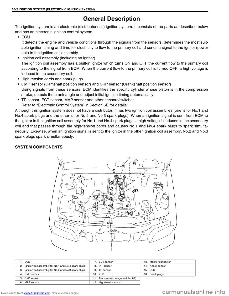
SYSTEM COMPONENTS
1. ECM 7. ECT sensor 13. Monitor connector
2. Ignition coil assembly for No.1 and No.4 spark plugs 8. IAT sensor 14. Knock sensor
3. Ignition coil assembly for No.2 and No.3 spark plugs 9. TP sensor 15. DLC
4. CMP sensor 10. VSS 16. Spark plugs
5. CKP sensor 11. Transmission range switch (A/T)
6. MAP sensor 12. High-tension cords
Page 657 of 687
Downloaded from www.Manualslib.com manuals search engine 6F-8 IGNITION SYSTEM (ELECTRONIC IGNITION SYSTEM)
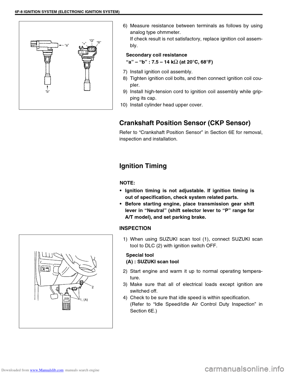
6) Measure resistance between terminals as follows by using
analog type ohmmeter.
If check result is not satisfactory, replace ignition coil assem-
bly.
Secondary coil resistance
“a” – “b” : 7.5 – 14 k
Ω (at 20°C, 68°F)
7) Install ignition coil assembly.
8) Tighten ignition coil bolts, and then connect ignition coil cou-
pler.
9) Install high-tension cord to ignition coil assembly while grip-
ping its cap.
10) Install cylinder head upper cover.
Crankshaft Position Sensor (CKP Sensor)
Refer to “Crankshaft Position Sensor” in Section 6E for removal,
inspection and installation.
Ignition Timing
INSPECTION
1) When using SUZUKI scan tool (1), connect SUZUKI scan
tool to DLC (2) with ignition switch OFF.
Special tool
(A) : SUZUKI scan tool
2) Start engine and warm it up to normal operating tempera-
ture.
3) Make sure that all of electrical loads except ignition are
switched off.
4) Check to be sure that idle speed is within specification.
(Refer to “Idle Speed/Idle Air Control Duty Inspection” in
Section 6E.)
NOTE:
Ignition timing is not adjustable. If ignition timing is
out of specification, check system related parts.
Before starting engine, place transmission gear shift
lever in “Neutral” (shift selector lever to “P” range for
A/T model), and set parking brake.
Page 661 of 687
Downloaded from www.Manualslib.com manuals search engine 6G-2 CRANKING SYSTEM
General Description
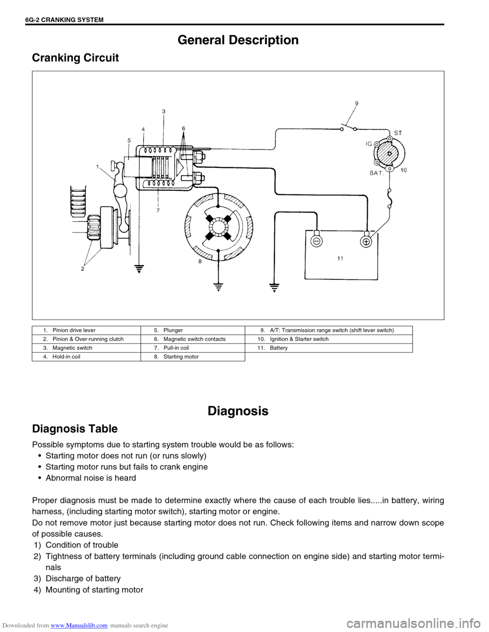
Cranking Circuit
Diagnosis
Diagnosis Table
Possible symptoms due to starting system trouble would be as follows:
Starting motor does not run (or runs slowly)
Starting motor runs but fails to crank engine
Abnormal noise is heard
Proper diagnosis must be made to determine exactly where the cause of each trouble lies.....in battery, wiring
harness, (including starting motor switch), starting motor or engine.
Do not remove motor just because starting motor does not run. Check following items and narrow down scope
of possible causes.
1) Condition of trouble
2) Tightness of battery terminals (including ground cable connection on engine side) and starting motor termi-
nals
3) Discharge of battery
4) Mounting of starting motor
1. Pinion drive lever 5. Plunger 9. A/T: Transmission range switch (shift lever switch)
2. Pinion & Over-running clutch 6. Magnetic switch contacts 10. Ignition & Starter switch
3. Magnetic switch 7. Pull-in coil 11. Battery
4. Hold-in coil 8. Starting motor
Page 676 of 687
Downloaded from www.Manualslib.com manuals search engine CHARGING SYSTEM 6H-9
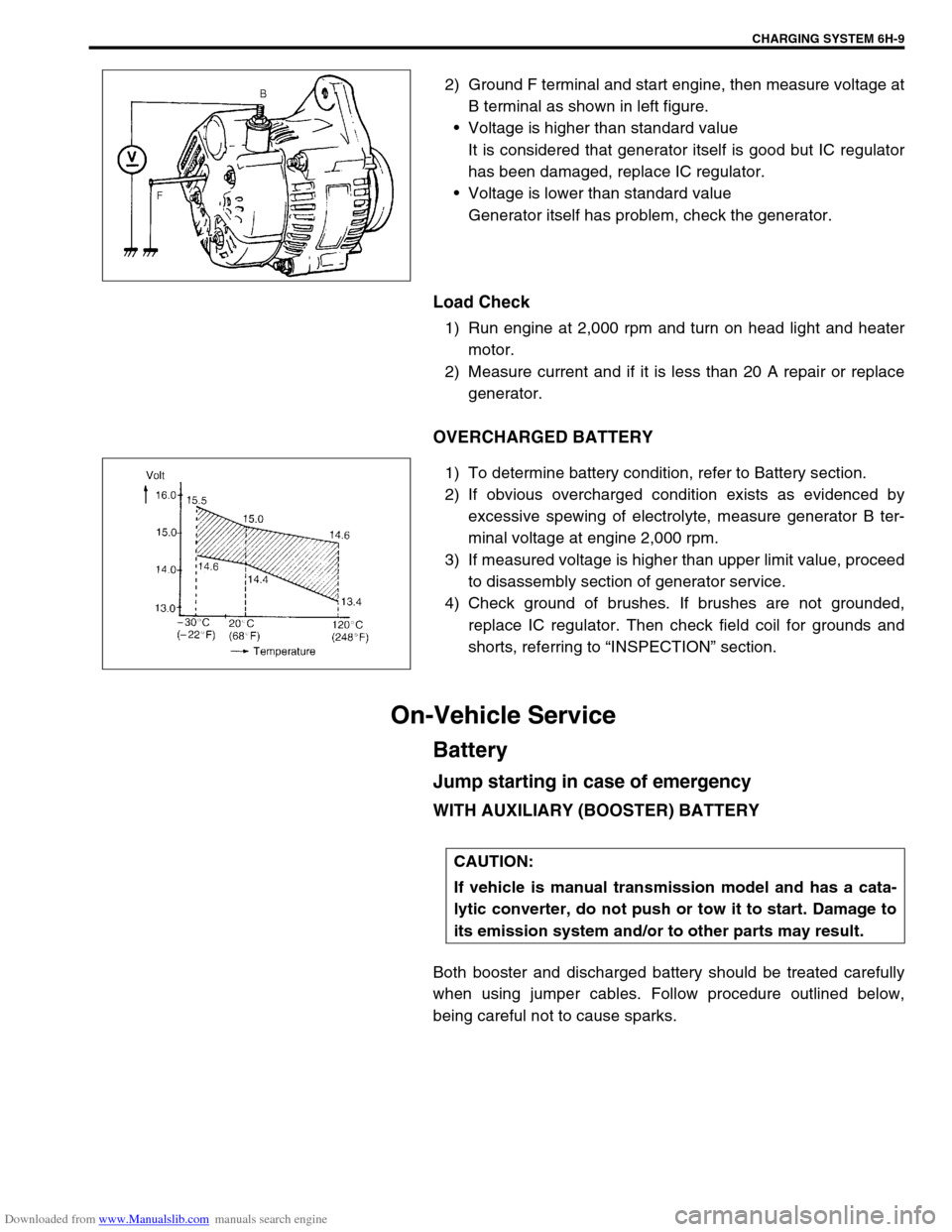
2) Ground F terminal and start engine, then measure voltage at
B terminal as shown in left figure.
Voltage is higher than standard value
It is considered that generator itself is good but IC regulator
has been damaged, replace IC regulator.
Voltage is lower than standard value
Generator itself has problem, check the generator.
Load Check
1) Run engine at 2,000 rpm and turn on head light and heater
motor.
2) Measure current and if it is less than 20 A repair or replace
generator.
OVERCHARGED BATTERY
1) To determine battery condition, refer to Battery section.
2) If obvious overcharged condition exists as evidenced by
excessive spewing of electrolyte, measure generator B ter-
minal voltage at engine 2,000 rpm.
3) If measured voltage is higher than upper limit value, proceed
to disassembly section of generator service.
4) Check ground of brushes. If brushes are not grounded,
replace IC regulator. Then check field coil for grounds and
shorts, referring to “INSPECTION” section.
On-Vehicle Service
Battery
Jump starting in case of emergency
WITH AUXILIARY (BOOSTER) BATTERY
Both booster and discharged battery should be treated carefully
when using jumper cables. Follow procedure outlined below,
being careful not to cause sparks.
CAUTION:
If vehicle is manual transmission model and has a cata-
lytic converter, do not push or tow it to start. Damage to
its emission system and/or to other parts may result.