Page 272 of 687

Downloaded from www.Manualslib.com manuals search engine BRAKES 5-11
Rear Drum Brake Shoe Adjustment
Rear brake has self-adjusting mechanism but it does require
adjustment for proper drum to shoe clearance when brake shoe
has been replaced or brake drum has been removed for some
other service.
Adjustment is automatically accomplished by depressing brake
pedal about 30 times with approximately 30 kg (66 Ibs) load after
all parts are installed.
Then check brake drum for dragging and brake system for proper
performance. After lowering vehicle from hoist, brake test should
be performed.
Parking Brake Inspection and Adjustment
INSPECTION
Hold center of parking brake lever grip and pull it up with 20 kg
(44 Ibs) force.
With parking brake lever pulled up as above, count ratchet
notches.
There should be 6 to 8 notches.
Also, check if both right and left rear wheels are locked firmly. To
count number of notches easily, listen to click sounds that ratchet
makes while pulling parking brake lever without pressing its but-
ton.
One click sound corresponds to one notch.NOTE:
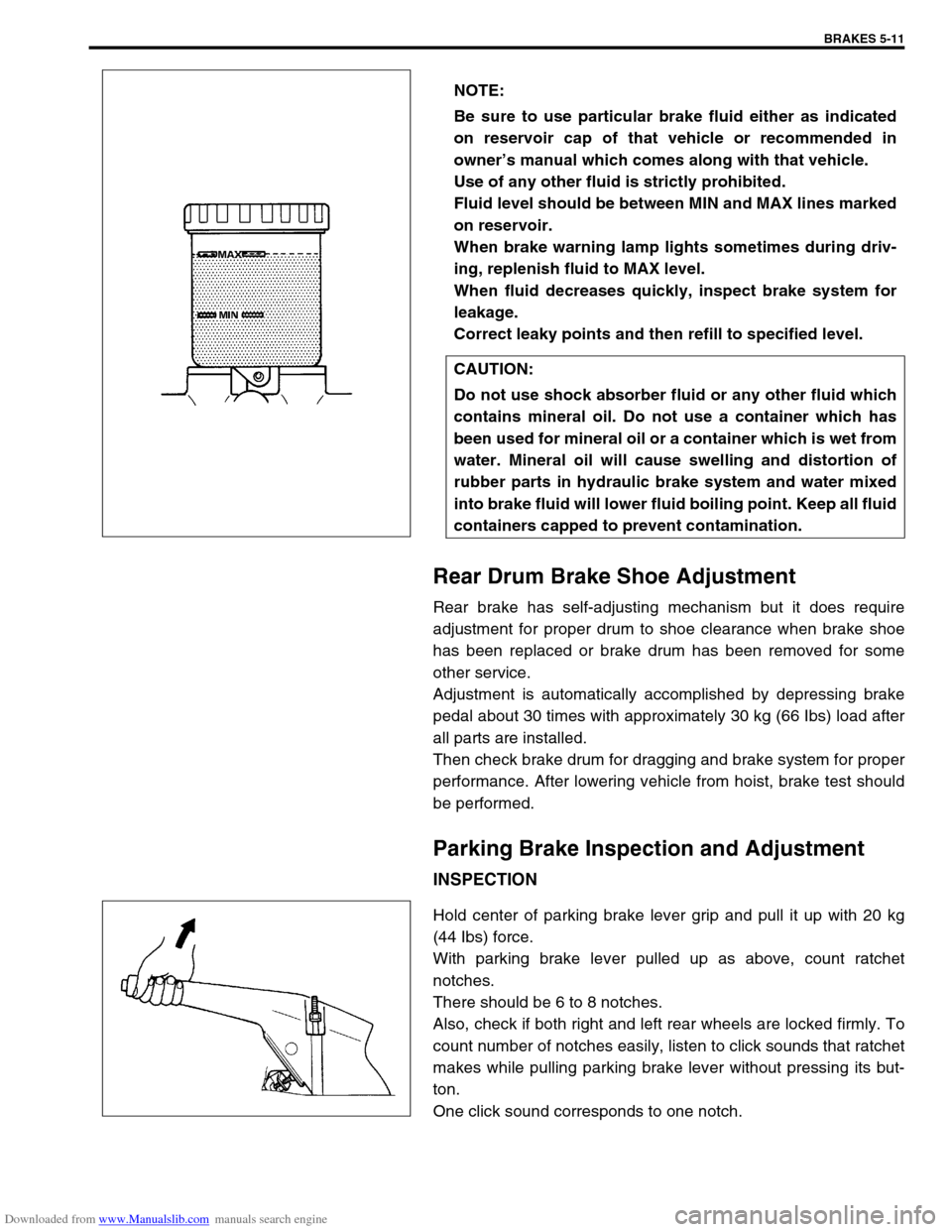
Be sure to use particular brake fluid either as indicated
on reservoir cap of that vehicle or recommended in
owner’s manual which comes along with that vehicle.
Use of any other fluid is strictly prohibited.
Fluid level should be between MIN and MAX lines marked
on reservoir.
When brake warning lamp lights sometimes during driv-
ing, replenish fluid to MAX level.
When fluid decreases quickly, inspect brake system for
leakage.
Correct leaky points and then refill to specified level.
CAUTION:
Do not use shock absorber fluid or any other fluid which
contains mineral oil. Do not use a container which has
been used for mineral oil or a container which is wet from
water. Mineral oil will cause swelling and distortion of
rubber parts in hydraulic brake system and water mixed
into brake fluid will lower fluid boiling point. Keep all fluid
containers capped to prevent contamination.
Page 273 of 687

Downloaded from www.Manualslib.com manuals search engine 5-12 BRAKES
If number of notches is out of specification, adjust cable by refer-
ring to adjustment procedure described on the following so as to
obtain specified parking brake stroke.
ADJUSTMENT
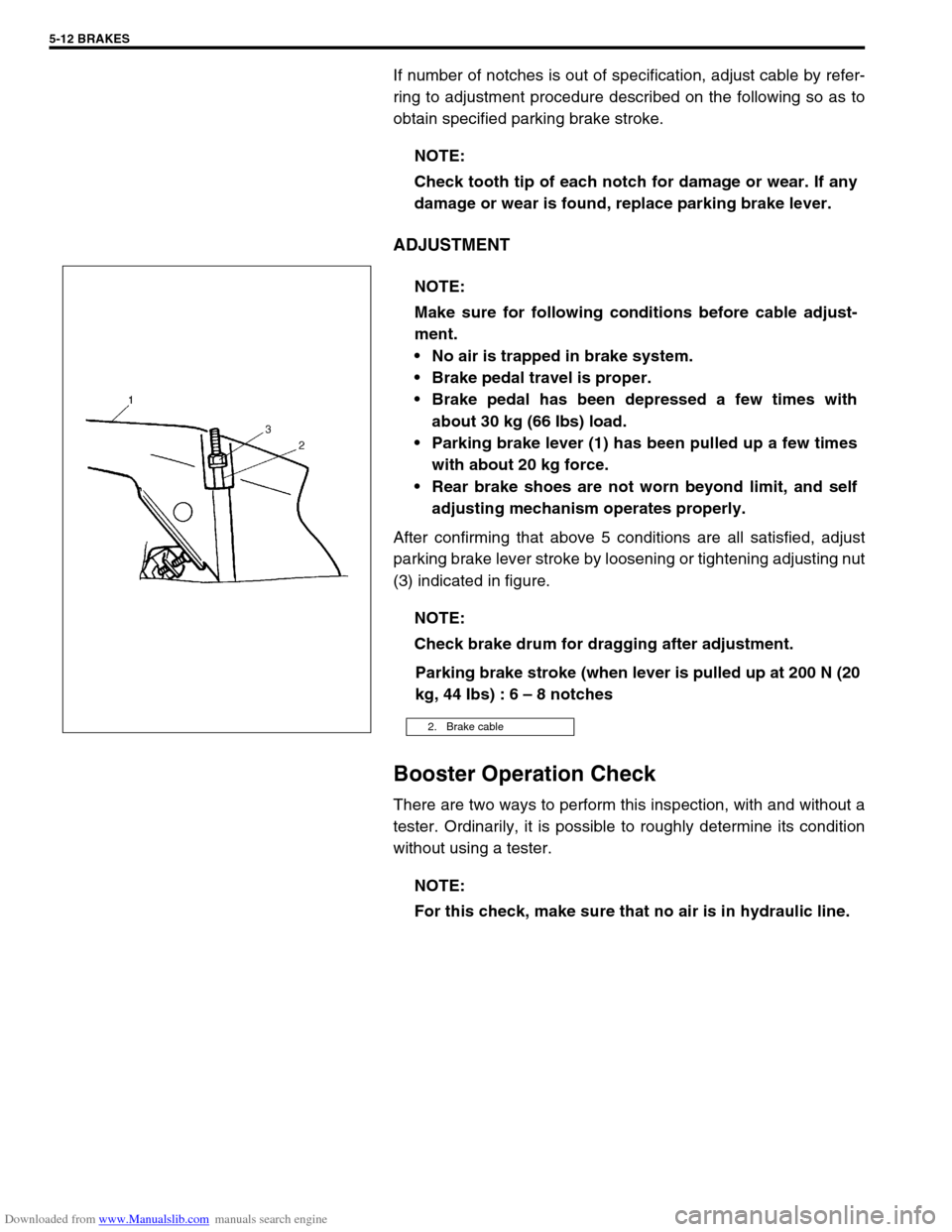
After confirming that above 5 conditions are all satisfied, adjust
parking brake lever stroke by loosening or tightening adjusting nut
(3) indicated in figure.
Parking brake stroke (when lever is pulled up at 200 N (20
kg, 44 Ibs) : 6 – 8 notches
Booster Operation Check
There are two ways to perform this inspection, with and without a
tester. Ordinarily, it is possible to roughly determine its condition
without using a tester.NOTE:
Check tooth tip of each notch for damage or wear. If any
damage or wear is found, replace parking brake lever.
NOTE:
Make sure for following conditions before cable adjust-
ment.
No air is trapped in brake system.
Brake pedal travel is proper.
Brake pedal has been depressed a few times with
about 30 kg (66 Ibs) load.
Parking brake lever (1) has been pulled up a few times
with about 20 kg force.
Rear brake shoes are not worn beyond limit, and self
adjusting mechanism operates properly.
NOTE:
Check brake drum for dragging after adjustment.
2. Brake cable
NOTE:
For this check, make sure that no air is in hydraulic line.
Page 290 of 687
Downloaded from www.Manualslib.com manuals search engine BRAKES 5-29
Rear Brake
Brake drum
REMOVAL
1) Hoist vehicle and pull up parking brake lever.
2) Remove wheel.
3) Release parking brake lever.
4) Loosen parking brake cable adjusting nut (1).
1. Brake back plate 5. Shoe return spring lower 9. Shoe hold down pin
2. Brake shoe 6. Adjuster lever 10. Wheel cylinder
: Apply brake fluid to piston cap
3. Spring and rod assembly 7. Adjuster spring Tightening torque
4. Parking brake shoe lever 8. Shoe hold down spring
Page 292 of 687

Downloaded from www.Manualslib.com manuals search engine BRAKES 5-31
Brake Shoe
Where lining is worn out beyond service limit, replace shoe.
If one of brake linings is to service limit, all linings must be
replaced at the same time.
Brake shoe thickness (lining + shoe rim) “a”
Standard (lining + rim) : 6.5 mm (0.26 in.)
Service limit : 3.0 mm (0.12 in.)
INSTALLATION
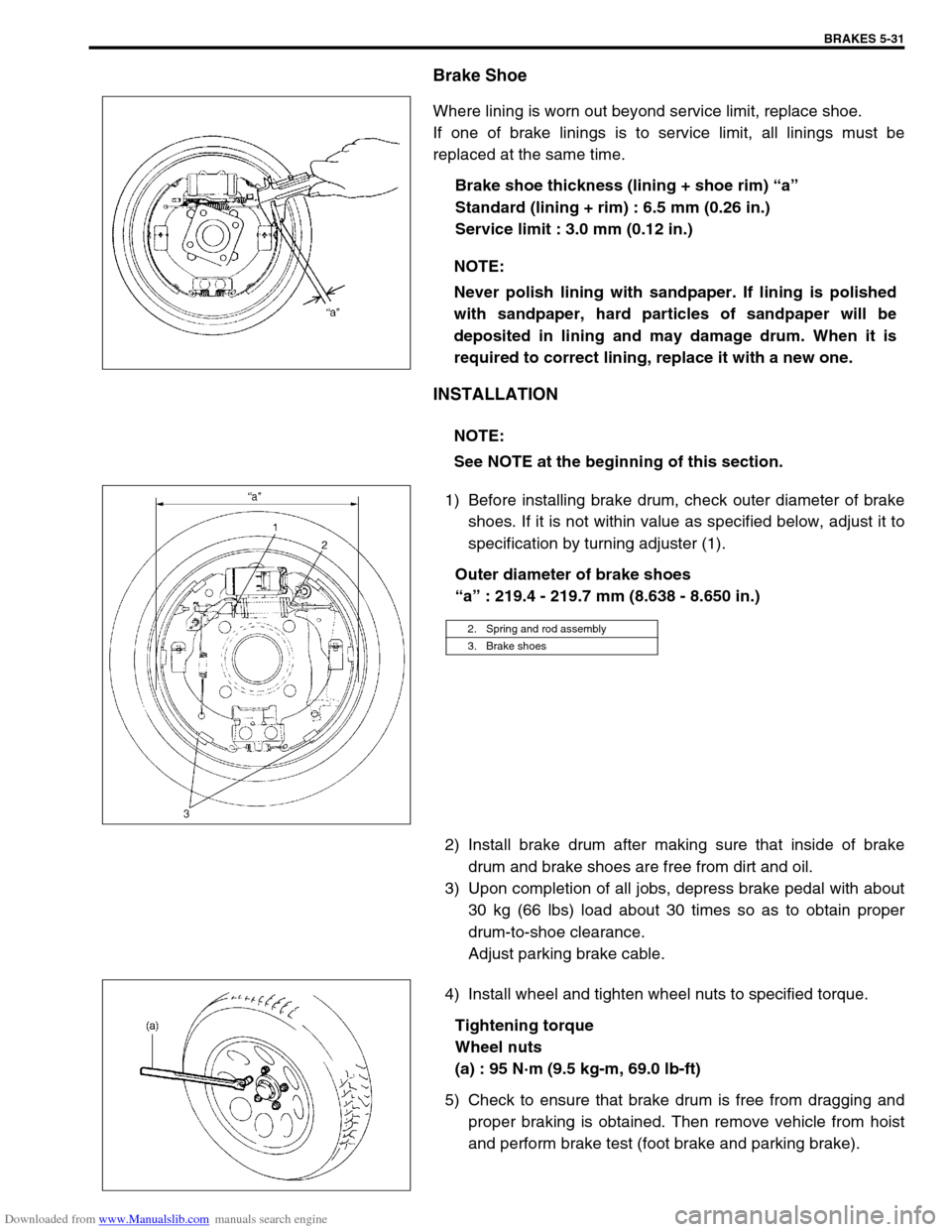
1) Before installing brake drum, check outer diameter of brake
shoes. If it is not within value as specified below, adjust it to
specification by turning adjuster (1).
Outer diameter of brake shoes
“a” : 219.4 - 219.7 mm (8.638 - 8.650 in.)
2) Install brake drum after making sure that inside of brake
drum and brake shoes are free from dirt and oil.
3) Upon completion of all jobs, depress brake pedal with about
30 kg (66 lbs) load about 30 times so as to obtain proper
drum-to-shoe clearance.
Adjust parking brake cable.
4) Install wheel and tighten wheel nuts to specified torque.
Tightening torque
Wheel nuts
(a) : 95 N·m (9.5 kg-m, 69.0 lb-ft)
5) Check to ensure that brake drum is free from dragging and
proper braking is obtained. Then remove vehicle from hoist
and perform brake test (foot brake and parking brake). NOTE:
Never polish lining with sandpaper. If lining is polished
with sandpaper, hard particles of sandpaper will be
deposited in lining and may damage drum. When it is
required to correct lining, replace it with a new one.
NOTE:
See NOTE at the beginning of this section.
2. Spring and rod assembly
3. Brake shoes
Page 293 of 687
Downloaded from www.Manualslib.com manuals search engine 5-32 BRAKES
Brake shoe
REMOVAL
1) Remove brake drum referring to “Brake Drum” in this sec-
tion.
2) Remove shoe return spring lower (3), spring and rod assem-
bly (4) and shoe hold down springs (2) by turning shoe hold
down pins (1).
3) Remove parking brake shoe lever (5) from brake back plate.
INSPECT
Inspect lever for free movement against brake shoe web. If
defective, correct or replace.
Inspect ratchet or thread rod part for wear, sticking and cor-
rosion.
Inspect for damage or weakening.
Inspect each part with arrow for rust. If found defective,
replace.
INSTALLATION
Assemble parts as shown in reverse order of removal.
1) Apply rubber grease to brake back plate and parking brake
shoe lever as shown in the figure. WARNING:
Use special care when installing brake shoe return
spring. Failure in its proper installation may allow it to
spring back and cause personal injury.
1. Apply rubber grease
Page 294 of 687
Downloaded from www.Manualslib.com manuals search engine BRAKES 5-33
2) Install shoe hold down springs (2) by pushing them down in
place and turning hold down pins (1).
3) Install shoe return spring and parking brake shoe lever
spring.
4) For procedure hereafter, refer to “Brake Drum” in this sec-
tion.
Wheel Cylinder
REMOVAL
1) Remove brake drum referring to “Brake Drum” in this sec-
tion.
2) Remove brake shoe referring to “Brake Shoe” in this section.
3) Loosen brake pipe flare nut (or nuts) but only within the
extent that fluid does not leak.
4) Remove wheel cylinder mounting bolts. Disconnect brake
pipe (or pipes) from wheel cylinder and put wheel cylinder
breather plug cap (1) onto pipe to prevent fluid from spilling.
INSPECTION
Inspect wheel cylinder disassembled parts for wear, cracks, cor-
rosion or damage.
3. Shoe return spring lower
4. Spring and rod assembly
5. Adjuster lever
6. Adjuster spring
NOTE:
Clean wheel cylinder components with brake fluid.
Page 313 of 687

Downloaded from www.Manualslib.com manuals search engine 5-52 BRAKES
Parking Brake Lever/Cable
Parking brake lever
REMOVAL
1) Hoist vehicle and release parking brake lever.
2) Disconnect negative cable at battery.
3) Remove parking brake lever cover.
4) Disconnect lead wire of parking brake switch at coupler.
5) Remove adjusting nut.
6) Loosen bracket nut (3) and disconnect parking brake cables
(2) from equalizer (4).
7) Remove parking brake lever bolts and then remove parking
brake lever assembly (1).
INSTALLATION
1) Install in reverse order of REMOVAL procedure.
Equalizer angle “a” : within 15 degrees
Tightening torque
Parking brake lever bolts
(a) : 23 N·m (2.3 kg-m, 17.0 lb-ft)
2) After all parts are installed, parking brake lever needs to be
adjusted. Refer to “Parking Brake Inspection and Adjust-
ment” in this section.
3) Check brake drum for dragging and brake system for proper
performance. NOTE:
Don’t disassemble parking brake lever switch. It must be
removed and installed as a complete switch assembly.
1. Parking brake lever
2. Parking brake cable
3. Adjusting nut
4. Equalizer
Page 314 of 687
Downloaded from www.Manualslib.com manuals search engine BRAKES 5-53
Parking Brake Cable
REMOVAL
1) Raise, suitably support vehicle and remove wheel if necessary.
2) Remove parking brake cable.
INSTALLATION
1) Install it by reversing removal procedure, noting the following points.
Install clamps properly referring to figure below.
Tighten bolts and nuts to specified torque.
2) Upon completion of installation, adjust cable. (Refer to “Parking Brake Inspection and Adjustment” in this
section.) Then check brake drum for dragging and brake system for proper performance. After removing
vehicle from hoist, brake test should be performed.
E : View E J : View J 2. Floor Tightening torque
G : View G K : View K 3. Cross member
H : View H 1. Bracket 4. Clamp