Page 63 of 687

Downloaded from www.Manualslib.com manuals search engine 1B-2 AIR CONDITIONING (OPTIONAL)
Evacuating ................................................. 1B-23
Evacuating procedure ............................ 1B-23
Charging .................................................... 1B-25
Charging procedure ............................... 1B-25
Removing Manifold Gauge Set .................. 1B-28
Leak Test ................................................... 1B-28
On-Vehicle Service ...................................... 1B-29
Service Precaution ..................................... 1B-29
Refrigerant line ....................................... 1B-29
Handling refrigerant HFC-134a
(R-134a) ................................................. 1B-30
Condenser Assembly ................................. 1B-31
Receiver / Dryer ......................................... 1B-32
Condenser Cooling Fan Assembly ............ 1B-33Cooling Unit (Evaporator) .......................... 1B-34
A/C Evaporator Thermistor (A/C Evaporator
Temperature Sensor)................................. 1B-37
Expansion Valve ........................................ 1B-37
Dual Pressure Switch ................................ 1B-38
A/C Switch ................................................. 1B-39
Condenser Cooling Fan Motor Relay ........ 1B-39
Compressor ............................................... 1B-39
Magnet Clutch............................................ 1B-41
Lip Type Seal ............................................. 1B-45
Tightening Torque Specification................ 1B-46
Required Service Materials ......................... 1B-47
Special Tools ............................................... 1B-47
Page 76 of 687

Downloaded from www.Manualslib.com manuals search engine AIR CONDITIONING (OPTIONAL) 1B-15
Compressor Drive Belt
INSPECTION
Check belt for wear and cracks, and replace as required.
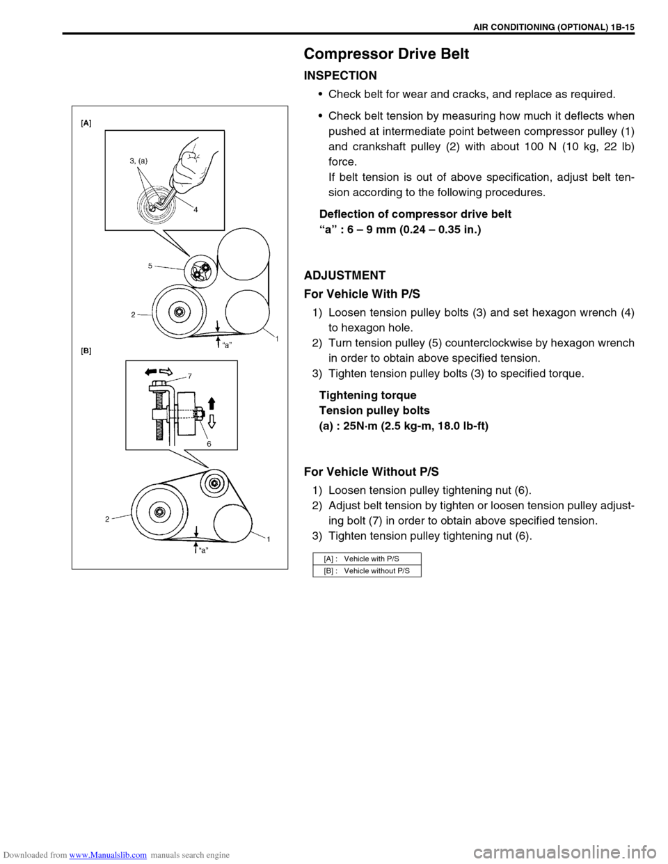
Check belt tension by measuring how much it deflects when
pushed at intermediate point between compressor pulley (1)
and crankshaft pulley (2) with about 100 N (10 kg, 22 lb)
force.
If belt tension is out of above specification, adjust belt ten-
sion according to the following procedures.
Deflection of compressor drive belt
“a” : 6 – 9 mm (0.24 – 0.35 in.)
ADJUSTMENT
For Vehicle With P/S
1) Loosen tension pulley bolts (3) and set hexagon wrench (4)
to hexagon hole.
2) Turn tension pulley (5) counterclockwise by hexagon wrench
in order to obtain above specified tension.
3) Tighten tension pulley bolts (3) to specified torque.
Tightening torque
Tension pulley bolts
(a) : 25N·m (2.5 kg-m, 18.0 lb-ft)
For Vehicle Without P/S
1) Loosen tension pulley tightening nut (6).
2) Adjust belt tension by tighten or loosen tension pulley adjust-
ing bolt (7) in order to obtain above specified tension.
3) Tighten tension pulley tightening nut (6).
[A] : Vehicle with P/S
[B] : Vehicle without P/S
Page 90 of 687

Downloaded from www.Manualslib.com manuals search engine AIR CONDITIONING (OPTIONAL) 1B-29
On-Vehicle Service
Service Precaution
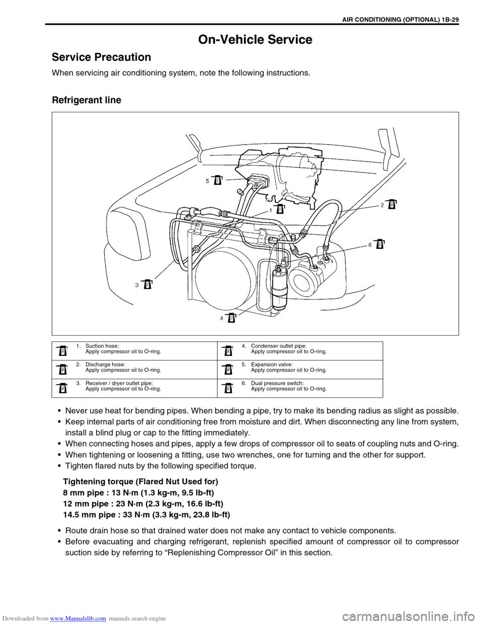
When servicing air conditioning system, note the following instructions.
Refrigerant line
Never use heat for bending pipes. When bending a pipe, try to make its bending radius as slight as possible.
Keep internal parts of air conditioning free from moisture and dirt. When disconnecting any line from system,
install a blind plug or cap to the fitting immediately.
When connecting hoses and pipes, apply a few drops of compressor oil to seats of coupling nuts and O-ring.
When tightening or loosening a fitting, use two wrenches, one for turning and the other for support.
Tighten flared nuts by the following specified torque.
Tightening torque (Flared Nut Used for)
8 mm pipe : 13 N·m (1.3 kg-m, 9.5 lb-ft)
12 mm pipe : 23 N·m (2.3 kg-m, 16.6 lb-ft)
14.5 mm pipe : 33 N·m (3.3 kg-m, 23.8 lb-ft)
Route drain hose so that drained water does not make any contact to vehicle components.
Before evacuating and charging refrigerant, replenish specified amount of compressor oil to compressor
suction side by referring to “Replenishing Compressor Oil” in this section.
1. Suction hose:
Apply compressor oil to O-ring.4. Condenser outlet pipe:
Apply compressor oil to O-ring.
2. Discharge hose:
Apply compressor oil to O-ring.5. Expansion valve:
Apply compressor oil to O-ring.
3. Receiver / dryer outlet pipe:
Apply compressor oil to O-ring.6. Dual pressure switch:
Apply compressor oil to O-ring.
Page 99 of 687

Downloaded from www.Manualslib.com manuals search engine 1B-38 AIR CONDITIONING (OPTIONAL)
INSTALLATION
Reverse removal procedure for installation, and then note the fol-
lowing instructions.
Replenish specified amount of compressor oil to compressor
suction side by referring to “Replenishing Compressor Oil” in
this section.
Evacuate and charge refrigerant by referring to “Evacuation”
and “Charging” in this section.
Dual Pressure Switch
INSPECTION
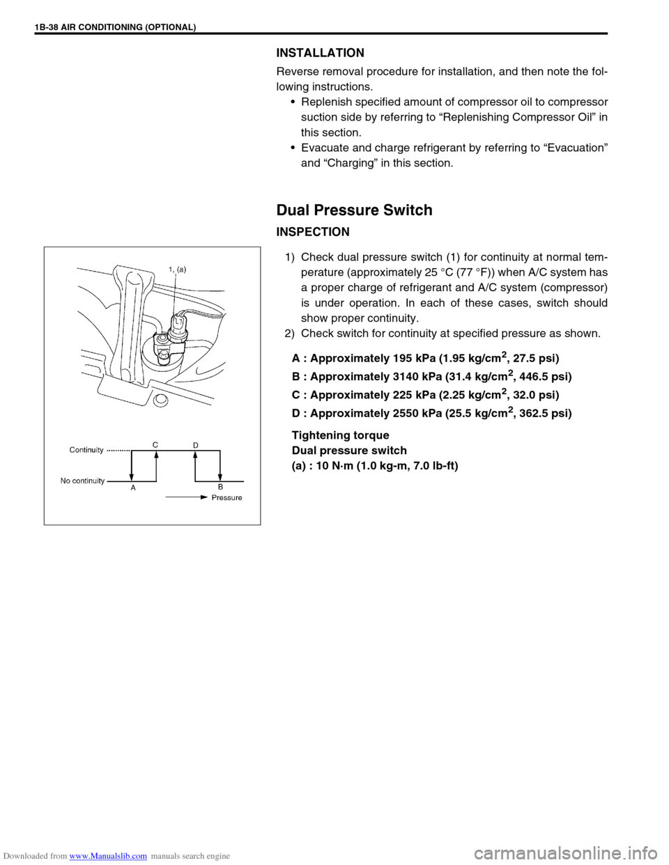
1) Check dual pressure switch (1) for continuity at normal tem-
perature (approximately 25 °C (77 °F)) when A/C system has
a proper charge of refrigerant and A/C system (compressor)
is under operation. In each of these cases, switch should
show proper continuity.
2) Check switch for continuity at specified pressure as shown.
A : Approximately 195 kPa (1.95 kg/cm
2, 27.5 psi)
B : Approximately 3140 kPa (31.4 kg/cm
2, 446.5 psi)
C : Approximately 225 kPa (2.25 kg/cm
2, 32.0 psi)
D : Approximately 2550 kPa (25.5 kg/cm
2, 362.5 psi)
Tightening torque
Dual pressure switch
(a) : 10 N·m (1.0 kg-m, 7.0 lb-ft)
Page 102 of 687
Downloaded from www.Manualslib.com manuals search engine AIR CONDITIONING (OPTIONAL) 1B-41
Magnet Clutch
1. Thermal switch 6. Magnet clutch coil a. Front head bolt
: Tighten bolt “a” first, and next “b”.
2. Compressor body assembly 7. Compressor pulley b. Front head bolt
: Tighten bolt “a” first, and next “b”.
3. O-ring 8. Circlip c. Clutch plate bolt
4. Lip seal 9. Shim Tightening torque
5. Front head 10. Clutch plate Do not reuse.
Page 105 of 687
Downloaded from www.Manualslib.com manuals search engine 1B-44 AIR CONDITIONING (OPTIONAL)
3) Install magnet clutch.
a) Set magnet clutch squarely over clutch installation boss.
b) Place special tool onto clutch bearing.
Ensure that edge rests only on inner race of bearing.
Special tool
(A) : 09991-06010
4) Install snap ring (1) using special tool.
Special tool
(A) : 09900-06107
5) Adjust clearance between clutch plate (1) and magnet clutch
coil (2) by putting shim on compressor shaft.
Standard clearance between clutch plate and magnet
clutch coil
“a” : 0.3 – 0.6 mm (0.012 – 0.024 in.)
6) Tighten new clutch plate bolt (1) as specified torque.
Tightening torque
Clutch plate bolt
(a) : 14 N·m (1.4 kg-m, 10.5 lb-ft)
Special tool
(A) : 09991-06020
CAUTION:
Be careful not to scratch bearing seal.
Page 107 of 687

Downloaded from www.Manualslib.com manuals search engine 1B-46 AIR CONDITIONING (OPTIONAL)
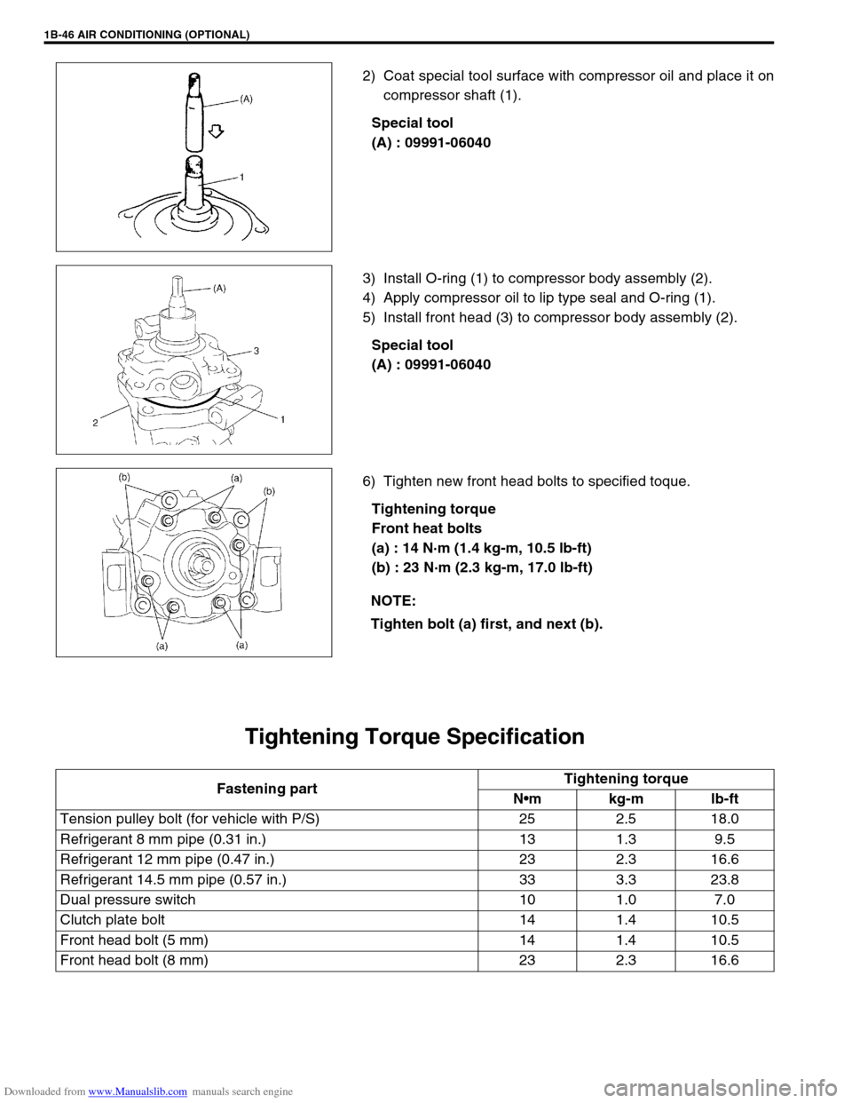
2) Coat special tool surface with compressor oil and place it on
compressor shaft (1).
Special tool
(A) : 09991-06040
3) Install O-ring (1) to compressor body assembly (2).
4) Apply compressor oil to lip type seal and O-ring (1).
5) Install front head (3) to compressor body assembly (2).
Special tool
(A) : 09991-06040
6) Tighten new front head bolts to specified toque.
Tightening torque
Front heat bolts
(a) : 14 N·m (1.4 kg-m, 10.5 lb-ft)
(b) : 23 N·m (2.3 kg-m, 17.0 lb-ft)
Tightening Torque Specification
NOTE:
Tighten bolt (a) first, and next (b).
Fastening partTightening torque
Nm kg-m lb-ft
Tension pulley bolt (for vehicle with P/S) 25 2.5 18.0
Refrigerant 8 mm pipe (0.31 in.) 13 1.3 9.5
Refrigerant 12 mm pipe (0.47 in.) 23 2.3 16.6
Refrigerant 14.5 mm pipe (0.57 in.) 33 3.3 23.8
Dual pressure switch 10 1.0 7.0
Clutch plate bolt 14 1.4 10.5
Front head bolt (5 mm) 14 1.4 10.5
Front head bolt (8 mm) 23 2.3 16.6
Page 112 of 687

Downloaded from www.Manualslib.com manuals search engine STEERING, SUSPENSION, WHEELS AND TIRES 3-3
Shimmy, Shake or
VibrationTire or wheel out of balance Balance wheels or replace tire
and/or wheel.
Loose wheel bearings Replace wheel bearing.
Loose wheel hub nuts Retighten.
Worn tie rod ends Replace tie rod end.
Worn king pin bearings or king pins Replace king pin bearing and/or
king pin.
Excessive wheel runout Repair or replace wheel and/or tire.
Blister or bump on tire Replace tire.
Excessively loaded radial runout of tire / wheel
assemblyReplace tire or wheel.
Disturbed front wheel alignment Check and adjust front wheel align-
ment.
Loose or worn steering linkage Tighten or replace steering linkage.
Loose steering gear box bolts Tighten box bolts.
Worn steering knuckle oil seal Replace.
Hard Steering
Bind in tie rod end ball studs or king pin bear-
ingsReplace tie rod end or king pin
bearing.
Disturbed front wheel alignment Check and adjust front wheel align-
ment.
Steering gear box adjustment Check and adjust steering gear
box.
Tire not adequately inflated Inflate tires to proper pressure.
Bind in steering column Repair or replace.
Low fluid level, loose drive belt or malfunction of
power steering system (if equipped with P/S)Check and correct.
Too Much Play in
SteeringWheel bearings worn Replace wheel bearing.
Steering gear box attachments loose Tighten or repair.
Steering gear box adjustments Check and adjust steering gear
box.
Worn steering shaft joints Replace joint.
Worn tie rod ends drug rod ball joints Replace tie rod end.
Worn king pin bearings or king pin Replace king pin bearing and/or
king pin.
Poor Returnability
Bind in tie rod end ball studs Replace tie rod end.
Bind in king pin bearings Replace king pin bearing.
Bind in steering column Repair or replace.
Steering gear box needing lubricant Check, repair or lubricate steering
gear box.
Disturbed front wheel alignment Check and adjust front wheel align-
ment.
Steering gear box not properly adjusted Check and adjust steering gear box
torque.
Tires not adequately inflated Adjust pressure.
Steering Noise
(Rattle or Chuckle)Loose bolts and nuts Retighten.
Broken or otherwise damaged wheel bearings Replace wheel bearing.
Worn or sticky tie rod ends Replace tire rod end.
Linkage joints needing grease Lubricate or replace. Condition Possible Cause Correction