Page 135 of 687
Downloaded from www.Manualslib.com manuals search engine 3B1-4 POWER STEERING (P/S) SYSTEM (If equipped)
Abnormal noise
(See NOTE “D”.)Air drawn in due to insufficient fluid Replenish fluid.
Air drawn in through pipe or hose joints Retighten or replace.
Belt slipping (loose) Adjust.
Worn belt Replace.
Loose steering linkage Retighten.
Loose gear box fixing bolt Retighten.
Loose pitman arm Retighten.
Pipes or hoses in contact with chassis Correct.
Defective pump vane Replace pump assembly.
Malfunction of flow control valve Replace gear box assembly.
Defective pump shaft bearing Replace pump assembly. Condition Possible Cause Correction
NOTE:
“C” : Turn steering wheel 90° at 35 km/h (22 mile/h) and let it free. If it returns more than 60° then, it
is normal.
“D” : Some hissing noise may be heard through steering column when turning steering wheel with
vehicle halted. It is from operation of the valve in the gear box and indicates nothing abnormal.
Page 136 of 687

Downloaded from www.Manualslib.com manuals search engine POWER STEERING (P/S) SYSTEM (If equipped) 3B1-5
Steering Wheel Play Check
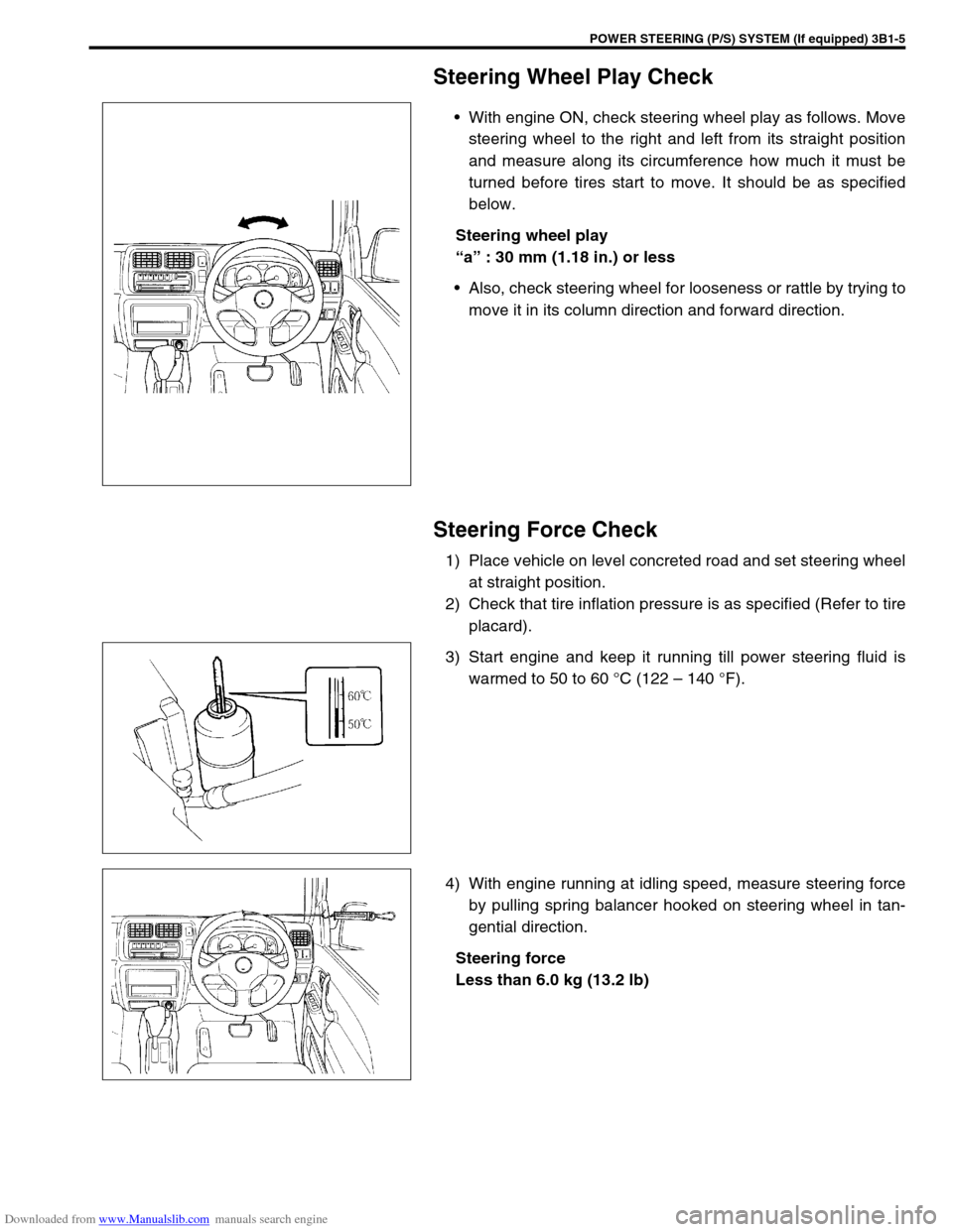
With engine ON, check steering wheel play as follows. Move
steering wheel to the right and left from its straight position
and measure along its circumference how much it must be
turned before tires start to move. It should be as specified
below.
Steering wheel play
“a” : 30 mm (1.18 in.) or less
Also, check steering wheel for looseness or rattle by trying to
move it in its column direction and forward direction.
Steering Force Check
1) Place vehicle on level concreted road and set steering wheel
at straight position.
2) Check that tire inflation pressure is as specified (Refer to tire
placard).
3) Start engine and keep it running till power steering fluid is
warmed to 50 to 60 °C (122 – 140 °F).
4) With engine running at idling speed, measure steering force
by pulling spring balancer hooked on steering wheel in tan-
gential direction.
Steering force
Less than 6.0 kg (13.2 lb)
Page 137 of 687

Downloaded from www.Manualslib.com manuals search engine 3B1-6 POWER STEERING (P/S) SYSTEM (If equipped)
Power Steering Belt Check
INSPECTION
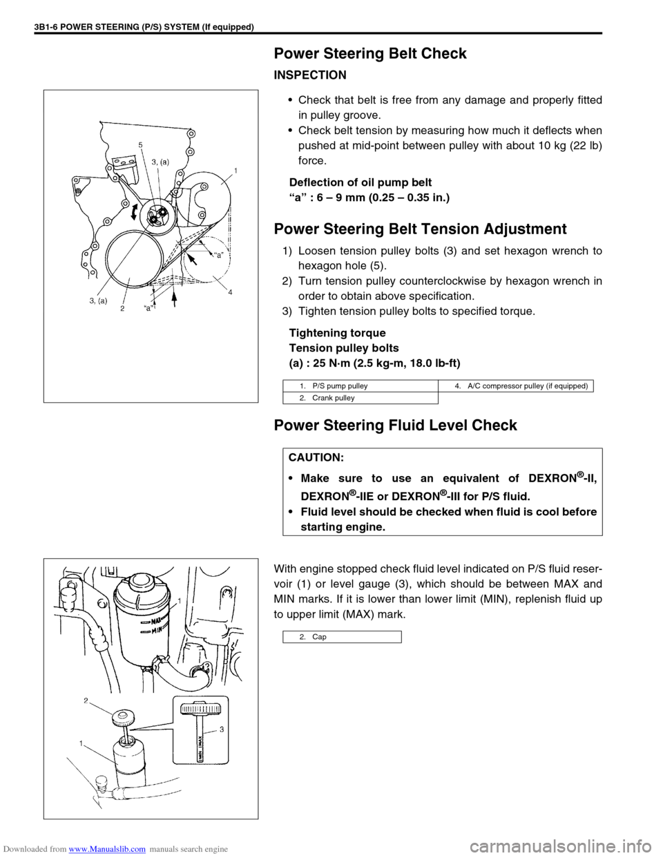
Check that belt is free from any damage and properly fitted
in pulley groove.
Check belt tension by measuring how much it deflects when
pushed at mid-point between pulley with about 10 kg (22 lb)
force.
Deflection of oil pump belt
“a” : 6 – 9 mm (0.25 – 0.35 in.)
Power Steering Belt Tension Adjustment
1) Loosen tension pulley bolts (3) and set hexagon wrench to
hexagon hole (5).
2) Turn tension pulley counterclockwise by hexagon wrench in
order to obtain above specification.
3) Tighten tension pulley bolts to specified torque.
Tightening torque
Tension pulley bolts
(a) : 25 N·m (2.5 kg-m, 18.0 lb-ft)
Power Steering Fluid Level Check
With engine stopped check fluid level indicated on P/S fluid reser-
voir (1) or level gauge (3), which should be between MAX and
MIN marks. If it is lower than lower limit (MIN), replenish fluid up
to upper limit (MAX) mark.
1. P/S pump pulley 4. A/C compressor pulley (if equipped)
2. Crank pulley
CAUTION:
Make sure to use an equivalent of DEXRON
®-II,
DEXRON
®-IIE or DEXRON®-III for P/S fluid.
Fluid level should be checked when fluid is cool before
starting engine.
2. Cap
Page 138 of 687
Downloaded from www.Manualslib.com manuals search engine POWER STEERING (P/S) SYSTEM (If equipped) 3B1-7
Idle-Up System Check
1) Warm up engine to normal operating temperature.
2) Turn A/C switch OFF, if equipped.
3) Turn steering wheel fully and check idle speed.
Engine idle speed drops a little momentarily when steering wheel is turned fully but returns to its specified
level immediately. If power steering pressure switch connector is connected, check the same with that con-
nector disconnected. Momentary drop of engine idle speed should be less when it is connected than when
disconnected.
Power Steering Fluid Leakage Check
Start engine and turn steering wheel fully to the right and left so that maximum hydraulic pressure is applied to
system. Then visually check gear box, P/S pump and P/S fluid reservoir respectively and each joint of hydraulic
pressure piping for leakage. During this check, however, never keep steering wheel turned fully for longer than
10 seconds.
Page 139 of 687

Downloaded from www.Manualslib.com manuals search engine 3B1-8 POWER STEERING (P/S) SYSTEM (If equipped)
Air Bleeding Procedure
AIR BLEEDING FROM SYSTEM
1) Jack up the front end of vehicle and apply rigid rack.
2) Fill P/S fluid reservoir with fluid up to specified level.
3) With engine running at idling speed, add fluid up to specified
level.
4) When fluid stops reducing, stop engine and leave P/S sys-
tem as it is for about 10 minutes.
5) After running engine at idling speed for 1 minute, stop it.
6) As a final step, check to make sure that fluid is up to speci-
fied level.
7) Check steering condition and P/S system for fluid leakage.
AIR BLEEDING FROM GEAR BOX
1) Remove steering gear box from vehicle referring to “Power
Steering (P/S) Gear Box” in this section.
2) Install special tool as shown.
Special tool
(A) : 09945-35010 CAUTION:
When air bleeding is not complete, it is indicated by
foaming fluid on level gauge or humming noise from P/S
pump.
NOTE:
Bleed air from system when P/S system has been ser-
viced in any way other than replacement of steering gear
box (e.g., disconnection of piping, replacement of P/S
pump). Never operate steering system while servicing.
Or Air Bleeding from gear box must be performed.
NOTE:
Bleed air from gear box:
When steering gear box has been replaced with a new
one.
When entry of air into hydraulic circuit of steering gear
box is suspected.
1. Steering gear box 3. High pressure hose / pipe
2. Low pressure hose / pipe
Page 140 of 687

Downloaded from www.Manualslib.com manuals search engine POWER STEERING (P/S) SYSTEM (If equipped) 3B1-9
3) After running engine at idling speed for 3 to 5 seconds, stop
it and add fluid up to specified level. Repeat this step a few
times.
4) Set steering gear box (1) to state [A] as shown.
5) With engine running at idling speed, turn input shaft by using
special tool in both directions as far as it locks till all foams
are gone.
Special tool
(B) : 09944-18211
6) Perform Step 5) but with steering gear box in state [B] this
time and then in state [C].
7) Set input shaft at neutral position (straight position).
8) Remove (special) tools and install steering gear box to vehi-
cle and P/S pipe / hose to steering gear box referring to
“Power Steering (P/S) Gear Box” in this section.
9) Bleed air in P/S system referring to “Air Bleeding Procedure”
in this section.
10) Install pitman arm and steering lower shaft to steering gear
box. NOTE:
Don’t operate steering system for this step.
NOTE:
Add fluid into P/S fluid reservoir whenever its level
lowers while servicing.
Turn input shaft till it locks, return it a little and turn it
again in the same direction till it locks. Repeat this
some times.
NOTE:
To change of state of gear box from [A] to [B] and from
[B] to [C], turn gear box in arrow direction in figures [A]
and [B].
NOTE:
As input shaft makes 4 full turns from lock to lock, neu-
tral position is obtained by turning it till it locks and turn-
ing it back by 2 full turns.
2. Vinyl tube (See-through tube)
NOTE:
Don’t install pitman arm and steering lower shaft to
steering gear box.
Installation of these parts will cause input shaft and/or
sector shaft to turn, allowing air to enter gear box.
Plug up opening after pipe or hose disconnection.
Page 141 of 687

Downloaded from www.Manualslib.com manuals search engine 3B1-10 POWER STEERING (P/S) SYSTEM (If equipped)
Hydraulic Pressure In P/S Circuit Check
1) Clean where pipe is connected thoroughly, then disconnect
high pressure hose from high pressure pipe connector and
connect oil pressure gauge (special tool) as shown.
Special tool
(A) : 09915-77410
(B) : 09915-77420
2) Bleed air.
3) With engine running at idling speed, keep turning steering
wheel to the right and left till fluid in P/S fluid reservoir is
warmed to 50 to 60 °C (122 – 140 °F)
4) Back pressure check
With engine running at idling speed and hands off from
steering wheel, check hydraulic pressure.
If back pressure exceeds 980 kPa (10 kg/cm
2, 142 psi),
check control valve and pipes for obstruction.
Back pressure : 980 kPa (10 kg/cm
2, 142 psi)
1. To gear box 4. Union bolt
2. Attachment 5. Pressure hose
3. Washer
1. P/S fluid reservoir 5. Low pressure side
2. P/S pump 6. High pressure side
3. Steering gear box 7. Valve (open)
4. Oil pump pressure gauge
Page 142 of 687

Downloaded from www.Manualslib.com manuals search engine POWER STEERING (P/S) SYSTEM (If equipped) 3B1-11
5) Relief pressure check
a) Increase engine speed to about 1,500 to 1,600 rpm.
Close valve (6) gradually while watching pressure increase
indicated on gauge (4) and take reading of relief pressure
(maximum hydraulic pressure).
If higher than 8,400 kPa (85 kg/cm
2, 1208 psi), malfunction
of relief valve.
If lower than 6,400 kPa (65 kg/cm
2, 925 psi), failure of P/S
pump or settling of relief valve spring.
Relief pressure
6,400 – 8,400 kPa (65 – 85 kg/cm
2, 925 – 1208 psi)
b) Next, open gauge valve (6) fully and increase engine speed
to about 1,500 to 1,600 r/min. Then turn steering wheel to
the left or right fully and take reading of relief pressure.
If lower than 6,400 kPa (65 kg/cm
2, 1280 psi), failure in
steering gear.
Relief pressure
6,400 – 8,400 kPa (65 – 85 kg/cm
2, 925 – 1208 psi) CAUTION:
Be sure not to keep gauge valve closed for longer than
10 seconds.
Never keep steering wheel turned fully for longer than
10 seconds.
1. P/S fluid reservoir 3. Steering gear box
2. P/S pump 5. High pressure side
1. P/S fluid reservoir 4. Oil pressure gauge
2. P/S pump 5. High pressure side
3. Steering gear box