Page 500 of 687

Downloaded from www.Manualslib.com manuals search engine ENGINE MECHANICAL (M13 ENGINE) 6A1-19
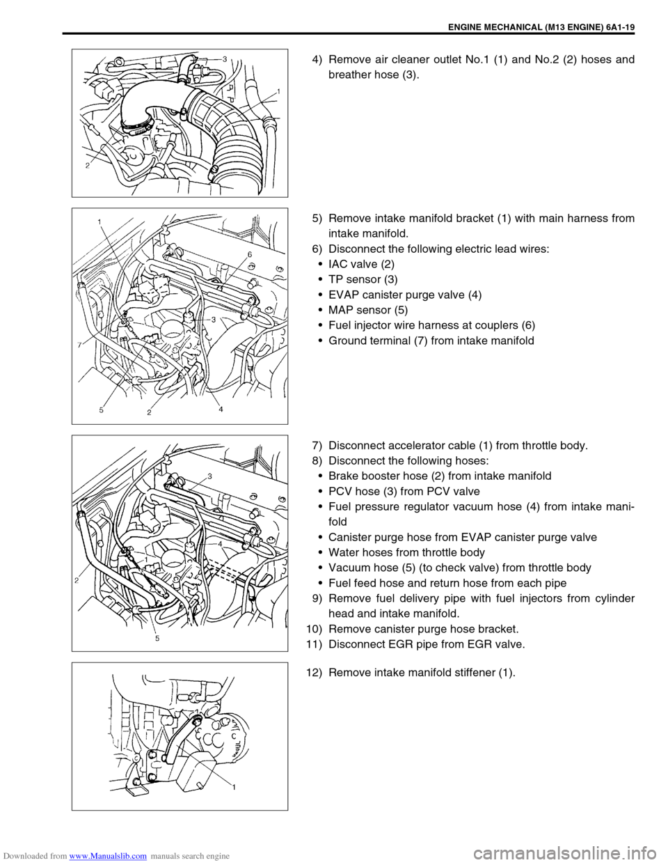
4) Remove air cleaner outlet No.1 (1) and No.2 (2) hoses and
breather hose (3).
5) Remove intake manifold bracket (1) with main harness from
intake manifold.
6) Disconnect the following electric lead wires:
IAC valve (2)
TP sensor (3)
EVAP canister purge valve (4)
MAP sensor (5)
Fuel injector wire harness at couplers (6)
Ground terminal (7) from intake manifold
7) Disconnect accelerator cable (1) from throttle body.
8) Disconnect the following hoses:
Brake booster hose (2) from intake manifold
PCV hose (3) from PCV valve
Fuel pressure regulator vacuum hose (4) from intake mani-
fold
Canister purge hose from EVAP canister purge valve
Water hoses from throttle body
Vacuum hose (5) (to check valve) from throttle body
Fuel feed hose and return hose from each pipe
9) Remove fuel delivery pipe with fuel injectors from cylinder
head and intake manifold.
10) Remove canister purge hose bracket.
11) Disconnect EGR pipe from EGR valve.
12) Remove intake manifold stiffener (1).
Page 607 of 687
Downloaded from www.Manualslib.com manuals search engine 6E-2 ENGINE AND EMISSION CONTROL SYSTEM
EGR system (If equipped) ...................... 6E-38
Evaporative emission (EVAP) control
system .................................................... 6E-39
PCV system ........................................... 6E-41Special Tools ............................................... 6E-42
Tightening Torque Specifications .............. 6E-43
Page 608 of 687
Downloaded from www.Manualslib.com manuals search engine ENGINE AND EMISSION CONTROL SYSTEM 6E-3
General Description
The engine and emission control system is divided into 4 major sub-systems: air intake system, fuel delivery
system, electronic control system and emission control system.
Air intake system includes air cleaner, throttle body, IAC valve and intake manifold.
Fuel delivery system includes fuel pump, delivery pipe, fuel pressure regulator, etc. Electronic control system
includes ECM, various sensors and controlled devices.
Emission control system includes EGR, EVAP and PCV system.
Page 646 of 687

Downloaded from www.Manualslib.com manuals search engine ENGINE AND EMISSION CONTROL SYSTEM 6E-41
EVAP CANISTER INSPECTION
1) Check outside of EVAP canister visually.
2) Disconnect vacuum hoses from EVAP canister.
3) Check that there should be no restriction of flow through
purge pipe (1) and air pipe (2) when air is blown (4) into tank
pipe (3).
If any faulty condition is found in above inspection replace.
PCV system
PCV HOSE INSPECTION
Check hoses for connection, leakage, clog and deterioration.
Replace as necessary.
PCV VALVE INSPECTION
1) Disconnect PCV valve (1) from cylinder head cover and
install plug to head cover hole.
2) Run engine at idle.
3) Place your finger over end of PCV valve (1) to check for vac-
uum. If there is no vacuum, check for clogged valve.
Replace as necessary. WARNING:
DO NOT SUCK nozzles on EVAP canister. Fuel vapor
inside EVAP canister is harmful.
NOTE:
Be sure to check that there is no obstruction in PCV
valve or its hoses before checking IAC duty, for
obstructed PCV valve or hose hampers its accurate
adjustment.
Page 647 of 687
Downloaded from www.Manualslib.com manuals search engine 6E-42 ENGINE AND EMISSION CONTROL SYSTEM
4) After checking vacuum, stop engine and remove PCV valve
(1).
Shake valve and listen for the rattle of check needle inside
the valve. If valve does not the rattle, replace valve.
5) After checking, remove plug and install PCV valve (1).
Special Tools
09912-57610 09912-58421 09912-58432 09912-58442
Checking tool plate Checking tool set
(See NOTE “A”.)Pressure hose Pressure gauge
09912-58490 09930-88530 09931-76011
3-way joint & hose Injector test lead SUZUKI scan tool
(Tech 1A) kit
(See NOTE “B”.)Mass storage cartridge
Page:
< prev 1-8 9-16 17-24