Page 500 of 687
Downloaded from www.Manualslib.com manuals search engine ENGINE MECHANICAL (M13 ENGINE) 6A1-19
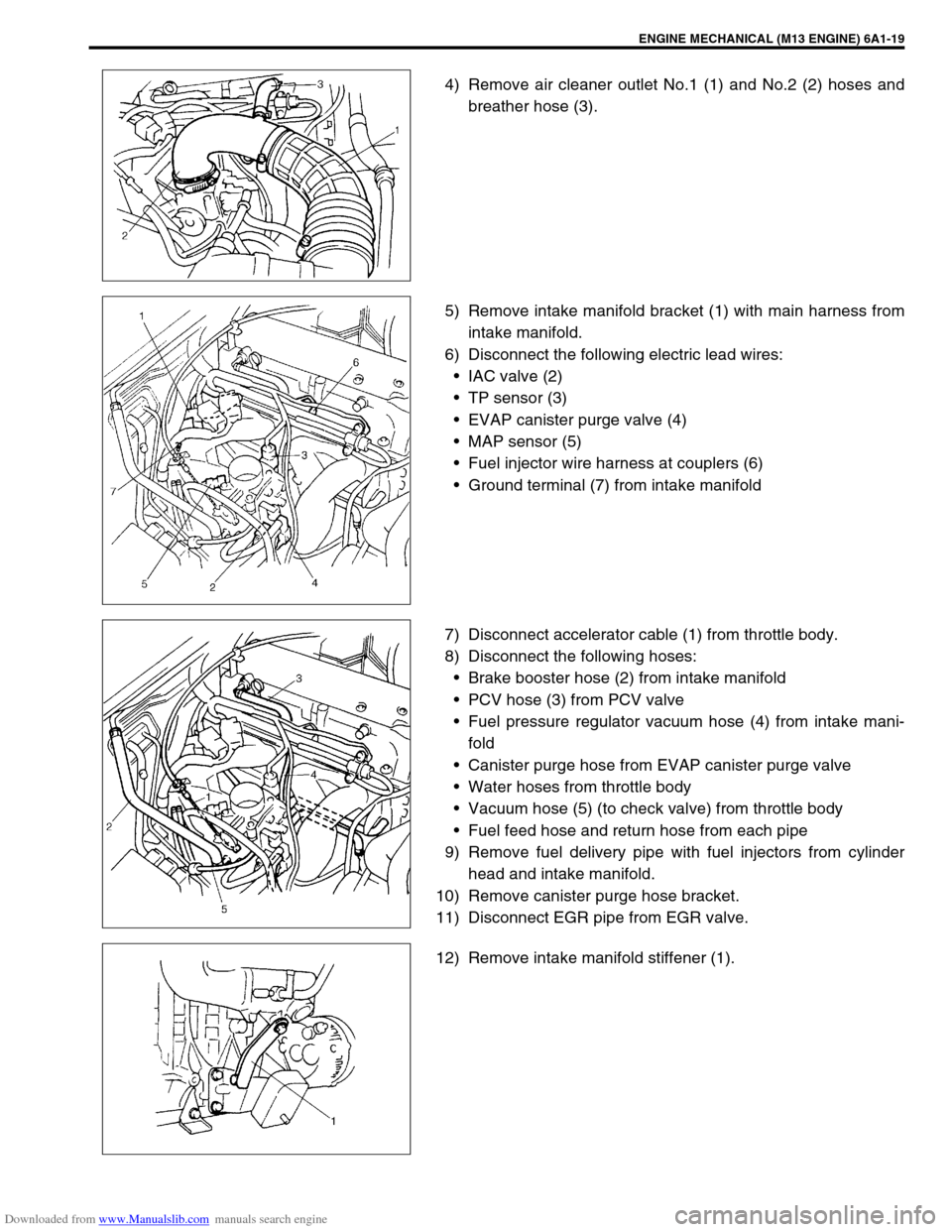
4) Remove air cleaner outlet No.1 (1) and No.2 (2) hoses and
breather hose (3).
5) Remove intake manifold bracket (1) with main harness from
intake manifold.
6) Disconnect the following electric lead wires:
IAC valve (2)
TP sensor (3)
EVAP canister purge valve (4)
MAP sensor (5)
Fuel injector wire harness at couplers (6)
Ground terminal (7) from intake manifold
7) Disconnect accelerator cable (1) from throttle body.
8) Disconnect the following hoses:
Brake booster hose (2) from intake manifold
PCV hose (3) from PCV valve
Fuel pressure regulator vacuum hose (4) from intake mani-
fold
Canister purge hose from EVAP canister purge valve
Water hoses from throttle body
Vacuum hose (5) (to check valve) from throttle body
Fuel feed hose and return hose from each pipe
9) Remove fuel delivery pipe with fuel injectors from cylinder
head and intake manifold.
10) Remove canister purge hose bracket.
11) Disconnect EGR pipe from EGR valve.
12) Remove intake manifold stiffener (1).
Page 531 of 687
Downloaded from www.Manualslib.com manuals search engine 6A1-50 ENGINE MECHANICAL (M13 ENGINE)
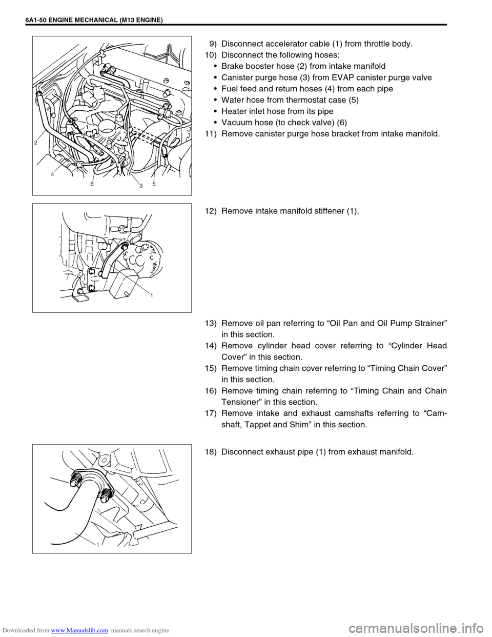
9) Disconnect accelerator cable (1) from throttle body.
10) Disconnect the following hoses:
Brake booster hose (2) from intake manifold
Canister purge hose (3) from EVAP canister purge valve
Fuel feed and return hoses (4) from each pipe
Water hose from thermostat case (5)
Heater inlet hose from its pipe
Vacuum hose (to check valve) (6)
11) Remove canister purge hose bracket from intake manifold.
12) Remove intake manifold stiffener (1).
13) Remove oil pan referring to “Oil Pan and Oil Pump Strainer”
in this section.
14) Remove cylinder head cover referring to “Cylinder Head
Cover” in this section.
15) Remove timing chain cover referring to “Timing Chain Cover”
in this section.
16) Remove timing chain referring to “Timing Chain and Chain
Tensioner” in this section.
17) Remove intake and exhaust camshafts referring to “Cam-
shaft, Tappet and Shim” in this section.
18) Disconnect exhaust pipe (1) from exhaust manifold.
Page 556 of 687
Downloaded from www.Manualslib.com manuals search engine ENGINE MECHANICAL (M13 ENGINE) 6A1-75
18) Remove heated oxygen sensor bracket from cylinder head
and detach No.1 heated oxygen sensor coupler from its
bracket.
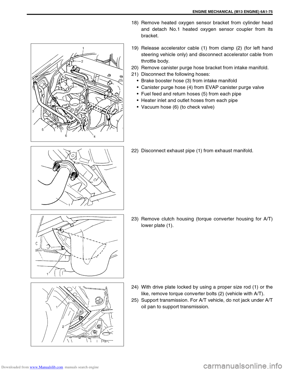
19) Release accelerator cable (1) from clamp (2) (for left hand
steering vehicle only) and disconnect accelerator cable from
throttle body.
20) Remove canister purge hose bracket from intake manifold.
21) Disconnect the following hoses:
Brake booster hose (3) from intake manifold
Canister purge hose (4) from EVAP canister purge valve
Fuel feed and return hoses (5) from each pipe
Heater inlet and outlet hoses from each pipe
Vacuum hose (6) (to check valve)
22) Disconnect exhaust pipe (1) from exhaust manifold.
23) Remove clutch housing (torque converter housing for A/T)
lower plate (1).
24) With drive plate locked by using a proper size rod (1) or the
like, remove torque converter bolts (2) (vehicle with A/T).
25) Support transmission. For A/T vehicle, do not jack under A/T
oil pan to support transmission.
Page 582 of 687
Downloaded from www.Manualslib.com manuals search engine ENGINE COOLING 6B-5
Diagnosis
Condition Possible Cause Correction
Engine overheats
Loose or broken water pump belt
Not enough coolant
Faulty thermostat
Faulty water pump
Dirty or bent radiator fins
Coolant leakage on cooling system
Defective cooling fan clutch
Plugged radiator
Faulty radiator cap
Maladjusted ignition timing
Dragging brakes
Slipping clutchAdjust or replace.
Check coolant level and add as
necessary.
Replace.
Replace.
Clean or remedy.
Repair.
Check and replace as necessary.
Check and replace radiator as
necessary.
Replace.
Check system related parts.
Adjust brake.
Adjust or replace.
Page 620 of 687
Downloaded from www.Manualslib.com manuals search engine ENGINE AND EMISSION CONTROL SYSTEM 6E-15
On-Vehicle Service
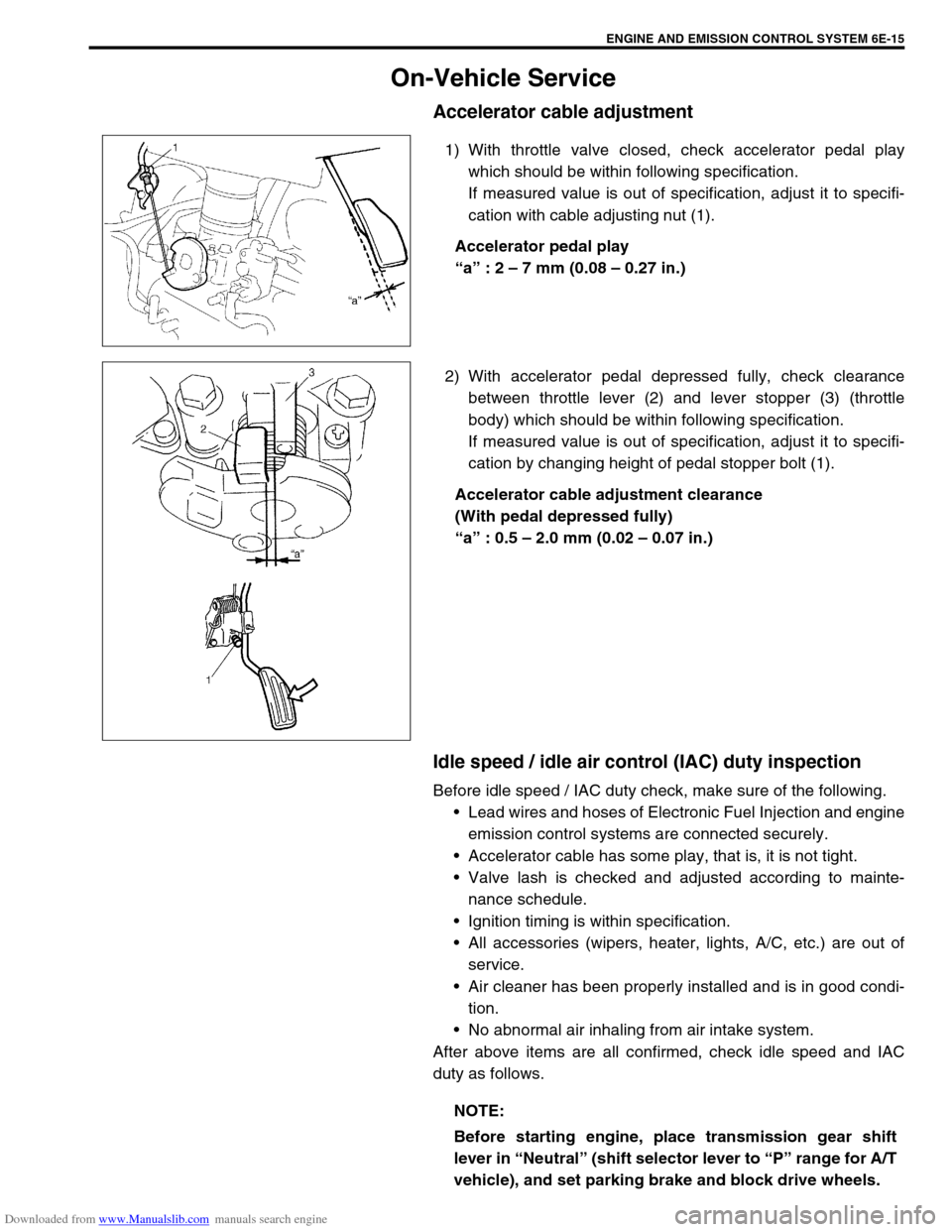
Accelerator cable adjustment
1) With throttle valve closed, check accelerator pedal play
which should be within following specification.
If measured value is out of specification, adjust it to specifi-
cation with cable adjusting nut (1).
Accelerator pedal play
“a” : 2 – 7 mm (0.08 – 0.27 in.)
2) With accelerator pedal depressed fully, check clearance
between throttle lever (2) and lever stopper (3) (throttle
body) which should be within following specification.
If measured value is out of specification, adjust it to specifi-
cation by changing height of pedal stopper bolt (1).
Accelerator cable adjustment clearance
(With pedal depressed fully)
“a” : 0.5 – 2.0 mm (0.02 – 0.07 in.)
Idle speed / idle air control (IAC) duty inspection
Before idle speed / IAC duty check, make sure of the following.
Lead wires and hoses of Electronic Fuel Injection and engine
emission control systems are connected securely.
Accelerator cable has some play, that is, it is not tight.
Valve lash is checked and adjusted according to mainte-
nance schedule.
Ignition timing is within specification.
All accessories (wipers, heater, lights, A/C, etc.) are out of
service.
Air cleaner has been properly installed and is in good condi-
tion.
No abnormal air inhaling from air intake system.
After above items are all confirmed, check idle speed and IAC
duty as follows.
NOTE:
Before starting engine, place transmission gear shift
lever in “Neutral” (shift selector lever to “P” range for A/T
vehicle), and set parking brake and block drive wheels.
Page 642 of 687
Downloaded from www.Manualslib.com manuals search engine ENGINE AND EMISSION CONTROL SYSTEM 6E-37
Fuel cut operation
INSPECTION
1) Warm up engine to normal operating temperature.
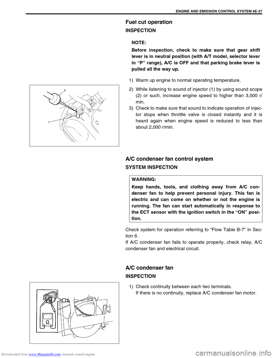
2) While listening to sound of injector (1) by using sound scope
(2) or such, increase engine speed to higher than 3,000 r/
min.
3) Check to make sure that sound to indicate operation of injec-
tor stops when throttle valve is closed instantly and it is
heard again when engine speed is reduced to less than
about 2,000 r/min.
A/C condenser fan control system
SYSTEM INSPECTION
Check system for operation referring to “Flow Table B-7” in Sec-
tion 6.
If A/C condenser fan fails to operate properly, check relay, A/C
condenser fan and electrical circuit.
A/C condenser fan
INSPECTION
1) Check continuity between each two terminals.
If there is no continuity, replace A/C condenser fan motor. NOTE:
Before inspection, check to make sure that gear shift
lever is in neutral position (with A/T model, selector lever
in “P” range), A/C is OFF and that parking brake lever is
pulled all the way up.
WARNING:
Keep hands, tools, and clothing away from A/C con-
denser fan to help prevent personal injury. This fan is
electric and can come on whether or not the engine is
running. The fan can start automatically in response to
the ECT sensor with the ignition switch in the “ON” posi-
tion.
Page 644 of 687

Downloaded from www.Manualslib.com manuals search engine ENGINE AND EMISSION CONTROL SYSTEM 6E-39
REMOVAL
1) Disconnect negative cable at battery.
2) Disconnect EGR valve connector.
3) Remove EGR pipe.
4) Remove EGR valve and gasket from cylinder head.
INSPECTION
1) Check resistance between following terminals of EGR valve
(1) in each pair.
If found faulty, replace EGR valve assembly.
EGR valve resistance
2) Remove carbon from EGR valve (1) gas passage.
3) Inspect valve (2), valve seat (3) and rod for fault, cracks,
bend or other damage.
If found faulty, replace EGR valve assembly.
INSTALLATION
Reverse removal procedure noting following.
Clean mating surface of valve and cylinder head.
Use new gaskets.
Evaporative emission (EVAP) control system
EVAP CANISTER PURGE INSPECTION
Terminal Standard resistance
A – B
C – B
F – E
D – E 20 – 24
Ω
ΩΩ Ω
NOTE:
Do not use any sharp-edged tool to remove carbon.
Be careful not to damage or bend EGR valve, valve seat
and rod.
NOTE:
Before inspection, check to make sure that gear shift
lever is in neutral position (with A/T model, selector lever
in “P” range) and that parking brake lever is pulled all the
way up.
Page 657 of 687
Downloaded from www.Manualslib.com manuals search engine 6F-8 IGNITION SYSTEM (ELECTRONIC IGNITION SYSTEM)
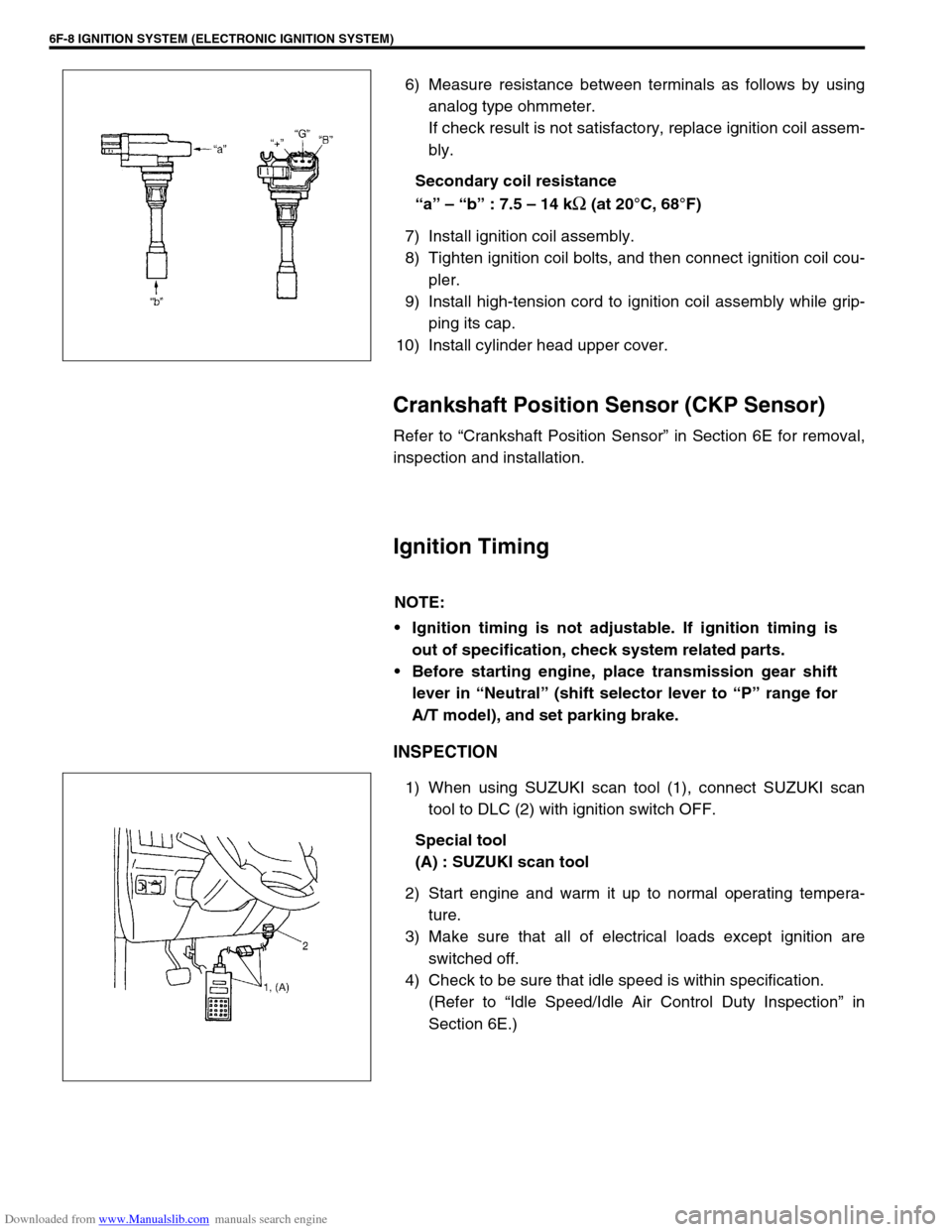
6) Measure resistance between terminals as follows by using
analog type ohmmeter.
If check result is not satisfactory, replace ignition coil assem-
bly.
Secondary coil resistance
“a” – “b” : 7.5 – 14 k
Ω (at 20°C, 68°F)
7) Install ignition coil assembly.
8) Tighten ignition coil bolts, and then connect ignition coil cou-
pler.
9) Install high-tension cord to ignition coil assembly while grip-
ping its cap.
10) Install cylinder head upper cover.
Crankshaft Position Sensor (CKP Sensor)
Refer to “Crankshaft Position Sensor” in Section 6E for removal,
inspection and installation.
Ignition Timing
INSPECTION
1) When using SUZUKI scan tool (1), connect SUZUKI scan
tool to DLC (2) with ignition switch OFF.
Special tool
(A) : SUZUKI scan tool
2) Start engine and warm it up to normal operating tempera-
ture.
3) Make sure that all of electrical loads except ignition are
switched off.
4) Check to be sure that idle speed is within specification.
(Refer to “Idle Speed/Idle Air Control Duty Inspection” in
Section 6E.)
NOTE:
Ignition timing is not adjustable. If ignition timing is
out of specification, check system related parts.
Before starting engine, place transmission gear shift
lever in “Neutral” (shift selector lever to “P” range for
A/T model), and set parking brake.