2005 SUZUKI JIMNY oil temperature
[x] Cancel search: oil temperaturePage 98 of 687

Downloaded from www.Manualslib.com manuals search engine AIR CONDITIONING (OPTIONAL) 1B-37
A/C Evaporator Thermistor (A/C Evaporator
Temperature Sensor)
INSPECTION
Check resistance between terminals for A/C evaporator ther-
mistor (1).
If check results are as not specified, replace thermistor.
A/C evaporator temperature sensor resistance
Expansion Valve
INSPECTION
Refer to “Performance Diagnosis” in this section.
REMOVAL
1) Disconnect negative (–) cable at battery.
2) Recover refrigerant from A/C system by referring to
“Recover” in this section.
3) Remove attaching bolt (1).
4) Remove suction hose (2) and receiver dryer outlet pipe (3)
from expansion valve (4).
5) Remove expansion valve (4).Sensor Temperature (°C (°F)) Resistance (k
Ω)
0 (32) 6.4 – 7.0
25 (77) 1.8 – 2.2
NOTE:
When A/C evaporator thermistor (1) removed, its should
be reinstalled in original position.
NOTE:
The amount of removed compressor oil must be mea-
sured for replenishing compressor oil.
Page 398 of 687

Downloaded from www.Manualslib.com manuals search engine ENGINE GENERAL INFORMATION AND DIAGNOSIS 6-41
Resistance Check
1) Disconnect ECM couplers (1) from ECM with ignition switch
OFF.
2) Check resistance between each terminal of couplers discon-
nected. CAUTION:
Never touch terminals of ECM itself or connect voltmeter
or ohmmeter (2).
CAUTION:
Be sure to connect ohmmeter probe from wire harness
side of coupler.
Be sure to turn OFF ignition switch for this check.
Resistance in table below represents that when parts
temperature is 20 °C (68 °F).
1. ECM coupler disconnected
2. Ohmmeter
TERMINALS CIRCUIT STANDARD RESISTANCE
E19-7 to E17-9
(For TYPE A) (See NOTE)HO2S-1 heater 5 – 6.4 Ω
E19-7 to E18-11
(For TYPE B) (See NOTE)
E18-4 to E17-9
(For TYPE A) (See NOTE)HO2S-2 heater 11.7 – 14.3 Ω
E19-9 to E19-2 No.1 injector 12.0 – 13.0 Ω
E19-21 to E19-2 No.2 injector 12.0 – 13.0 Ω
E19-31 to E19-2 No.3 injector 12.0 – 13.0 Ω
E19-8 to E19-2 No.4 injector 12.0 – 13.0 Ω
E19-28 to E19-2 EGR valve (stepper motor coil 4) 20 – 24 Ω
E19-17 to E19-2 EGR valve (stepper motor coil 3) 20 – 24 Ω
E19-29 to E19-2 EGR valve (stepper motor coil 2) 20 – 24 Ω
E19-18 to E19-2 EGR valve (stepper motor coil 1) 20 – 24 Ω
E19-4 to E19-2 EVAP canister purge valve 30 – 34 Ω
E18-19 to E17-9 (For
TYPE A) (See NOTE)Fuel pump relay 70 – 110 Ω
E18-19 to E18-11 (For
TYPE B) (See NOTE)
E18-1 to Body ground A/C compressor clutch 3 – 4.5 Ω
E18-18 to E19-2 A/C condenser fan control relay 70 – 110 Ω
E18-10 to E18-7 Main relay 70 – 110 Ω
E19-1 to Body ground Ground Continuity
E19-2 to Body ground Ground Continuity
E19-3 to Body ground Ground Continuity
NOTE:
For TYPE A and TYPE B, refer to the NOTE in “ECM Terminal Voltage Values Table” for applicable
model.
Page 539 of 687

Downloaded from www.Manualslib.com manuals search engine 6A1-58 ENGINE MECHANICAL (M13 ENGINE)
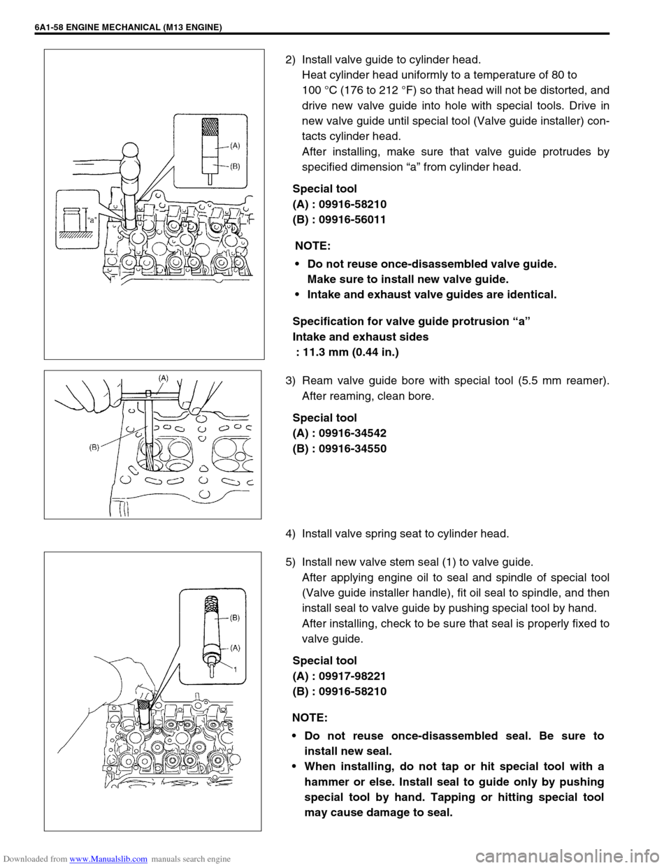
2) Install valve guide to cylinder head.
Heat cylinder head uniformly to a temperature of 80 to
100 °C (176 to 212 °F) so that head will not be distorted, and
drive new valve guide into hole with special tools. Drive in
new valve guide until special tool (Valve guide installer) con-
tacts cylinder head.
After installing, make sure that valve guide protrudes by
specified dimension “a” from cylinder head.
Special tool
(A) : 09916-58210
(B) : 09916-56011
Specification for valve guide protrusion “a”
Intake and exhaust sides
: 11.3 mm (0.44 in.)
3) Ream valve guide bore with special tool (5.5 mm reamer).
After reaming, clean bore.
Special tool
(A) : 09916-34542
(B) : 09916-34550
4) Install valve spring seat to cylinder head.
5) Install new valve stem seal (1) to valve guide.
After applying engine oil to seal and spindle of special tool
(Valve guide installer handle), fit oil seal to spindle, and then
install seal to valve guide by pushing special tool by hand.
After installing, check to be sure that seal is properly fixed to
valve guide.
Special tool
(A) : 09917-98221
(B) : 09916-58210NOTE:
Do not reuse once-disassembled valve guide.
Make sure to install new valve guide.
Intake and exhaust valve guides are identical.
NOTE:
Do not reuse once-disassembled seal. Be sure to
install new seal.
When installing, do not tap or hit special tool with a
hammer or else. Install seal to guide only by pushing
special tool by hand. Tapping or hitting special tool
may cause damage to seal.
Page 580 of 687

Downloaded from www.Manualslib.com manuals search engine ENGINE COOLING 6B-3
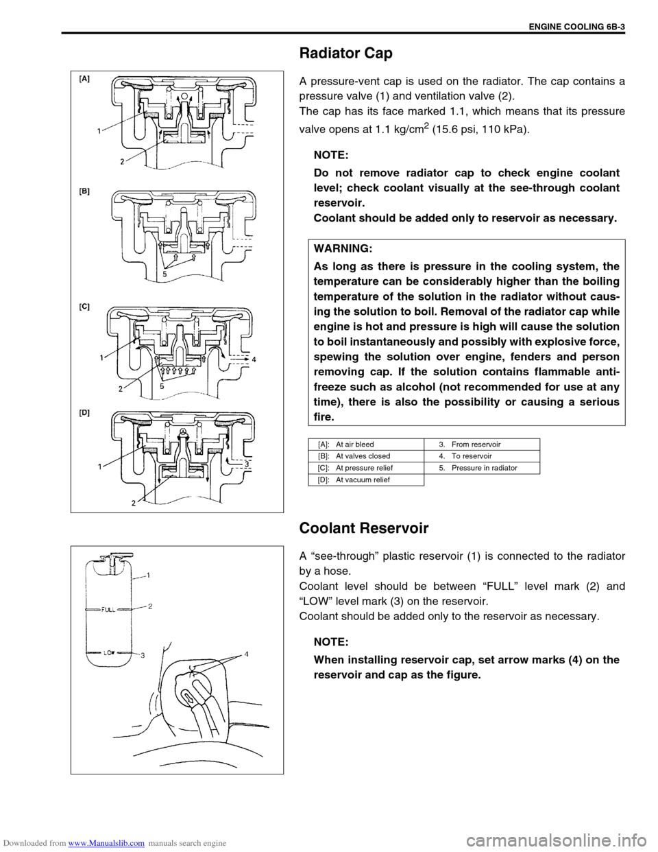
Radiator Cap
A pressure-vent cap is used on the radiator. The cap contains a
pressure valve (1) and ventilation valve (2).
The cap has its face marked 1.1, which means that its pressure
valve opens at 1.1 kg/cm
2 (15.6 psi, 110 kPa).
Coolant Reservoir
A “see-through” plastic reservoir (1) is connected to the radiator
by a hose.
Coolant level should be between “FULL” level mark (2) and
“LOW” level mark (3) on the reservoir.
Coolant should be added only to the reservoir as necessary.NOTE:
Do not remove radiator cap to check engine coolant
level; check coolant visually at the see-through coolant
reservoir.
Coolant should be added only to reservoir as necessary.
WARNING:
As long as there is pressure in the cooling system, the
temperature can be considerably higher than the boiling
temperature of the solution in the radiator without caus-
ing the solution to boil. Removal of the radiator cap while
engine is hot and pressure is high will cause the solution
to boil instantaneously and possibly with explosive force,
spewing the solution over engine, fenders and person
removing cap. If the solution contains flammable anti-
freeze such as alcohol (not recommended for use at any
time), there is also the possibility or causing a serious
fire.
[A]: At air bleed 3. From reservoir
[B]: At valves closed 4. To reservoir
[C]: At pressure relief 5. Pressure in radiator
[D]: At vacuum relief
NOTE:
When installing reservoir cap, set arrow marks (4) on the
reservoir and cap as the figure.
Page 583 of 687

Downloaded from www.Manualslib.com manuals search engine 6B-6 ENGINE COOLING
Maintenance
Coolant
The coolant recovery system is standard. The coolant in the radiator expands with heat, and the overflow is col-
lected in the reservoir.
When the system cools down, the coolant is drawn back into the radiator.
The cooling system has been filled at the factory with a quality coolant that is either 50/50 mixture of water and
anti-freeze / anti-corrosion coolant (ethylene glycol antifreeze).
The 50/50 mixture coolant solution provides freezing protection to – 36 °C ( – 33 °F).
Maintain cooling system freeze protection at – 36 °C ( – 33 °F) to ensure protection against corrosion and
loss of coolant from boiling.
This should be done even if freezing temperatures are not expected.
Add ethylene glycol base coolant when coolant has to be added because of coolant loss or to provide added
protection against freezing at temperature lower than – 36 °C ( – 33 °F).
Anti-freeze proportioning table
Coolant capacity Freezing temperature°C– 16– 36
°F3– 33
Anti-freeze / Anti-corrosion
coolant concentration%30 50
Ratio of compound
to cooling waterItr. 1.35/3.15 2.25/2.25
US pt. 2.85/6.65 4.75/4.75
Imp pt. 2.37/5.53 3.95/3.95
Engine radiator and heater 5.2 liters (11.0/9.2 US/lmp. pt.)
Reservoir 0.7 liters (1.5/1.2 US/lmp. pt.)
Total 5.9 liters (12.5/10.5 US/lmp. pt.)
NOTE:
Alcohol or methanol base coolant or plain water alone should not be used in cooling system at any
time as damage to cooling system could occur.
Even in a market where no freezing temperature is anticipated, mixture of 70% water and 30% ethyl-
ene glycol antifreeze (Antifreeze / Anticorrosion coolant) should be used for the purpose of corro-
sion protection and lubrication.
Page 671 of 687

Downloaded from www.Manualslib.com manuals search engine 6H-4 CHARGING SYSTEM
When keeping battery on vehicle over a long period of time, follow
instructions given below.
Weekly, start the engine and run it until it reaches normal
operating temperature with engine speed of 2,000 to 3,000
rpm. Make sure all electric switches are off before storing the
vehicle.
Recharge the battery twice a month to prevent it from dis-
charging excessively. This is especially important when
ambient temperature is low.
The battery discharges even when it is not used, while vehi-
cles are being stored. Battery electrolyte can freeze and bat-
tery case can crack at cold ambient condition if battery is not
properly charged.
2) Keep the battery cable connections clean.
The cable connections, particularly at the positive (+) termi-
nal post, tend to become corroded. The product of corrosion,
or rust, on the mating faces of conductors resists the flow of
current.
Clean the terminals and fittings periodically to ensure good
metal-to-metal contact, and grease the connections after
each cleaning to protect them against rusting.
3) Be always in the know as to the state of charge of the bat-
tery. The simplest way to tell the state of charge is to carry
out a hydrometer test. The hydrometer is an instrument for
measuring the specific gravity (S.G.) of the battery electro-
lyte. The S.G. of the electrolyte is indicative of the state of
charge. Refer to “HYDROMETER TEST” in this section.
Generator
The generator is a small and high performance type with an IC regulator incorporated.
The internal components are connected electrically as shown below figure.
The generator features are as follows:
Solid state regulator is mounted inside the generator.
All regulator components are enclosed into a solid mold.
This unit along with the brush holder assembly is attached to the rear housing.
The IC regulator uses integrated circuits and controls the voltage produced by the generator, and the volt-
age setting cannot be adjusted.
The generator rotor bearings contain enough grease to eliminate the need for periodic lubrication. Two
brushes carry current through the two slip rings to the field coil mounted on the rotor, and under normal con-
ditions will provide long period of attention-free service.
The stator windings are assembled on the inside of a laminated core that forms part of the generator frame.
A condenser mounted in the rear housing suppresses radio noise.
Page 674 of 687

Downloaded from www.Manualslib.com manuals search engine CHARGING SYSTEM 6H-7
How to use the temperature-corrected state-of-charge
graph
Suppose your S.G. reading is 1.28 and the battery temperature is
–5 °C (23 °F). Locate the intersection of the –5 °C line and the
1.28 S.G. line.
The intersection is within the “A” zone (shaded area in the graph)
and that means CHARGED STATE.
To know how much the battery is charged, draw a line parallel to
the zone demarcation line and extend it to the right till it meets
with the percentage scale. In the present example, the line meets
at about 85% point on the percentage scale. Therefore, the bat-
tery is charged up to the 85% level.
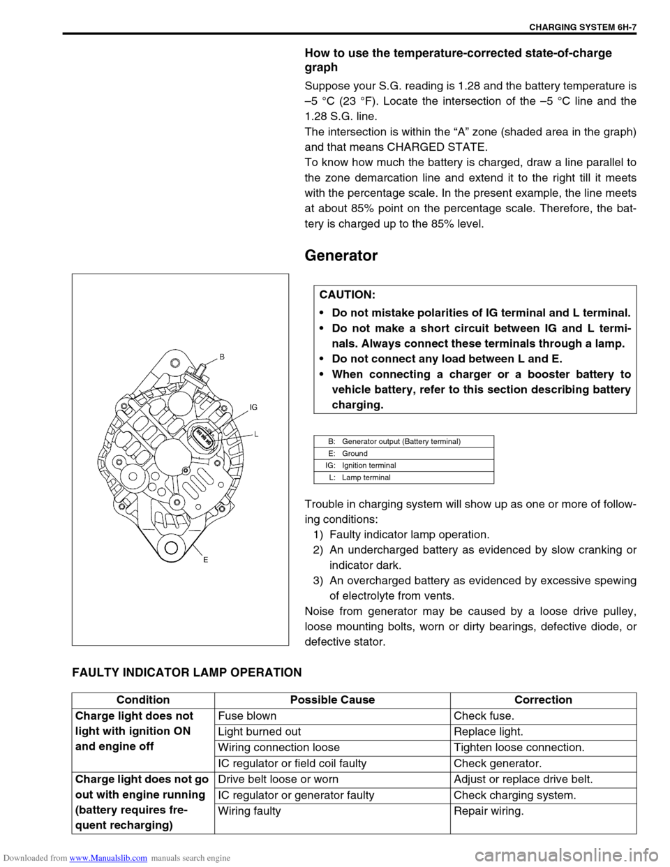
Generator
Trouble in charging system will show up as one or more of follow-
ing conditions:
1) Faulty indicator lamp operation.
2) An undercharged battery as evidenced by slow cranking or
indicator dark.
3) An overcharged battery as evidenced by excessive spewing
of electrolyte from vents.
Noise from generator may be caused by a loose drive pulley,
loose mounting bolts, worn or dirty bearings, defective diode, or
defective stator.
FAULTY INDICATOR LAMP OPERATION
CAUTION:
Do not mistake polarities of IG terminal and L terminal.
Do not make a short circuit between IG and L termi-
nals. Always connect these terminals through a lamp.
Do not connect any load between L and E.
When connecting a charger or a booster battery to
vehicle battery, refer to this section describing battery
charging.
B: Generator output (Battery terminal)
E: Ground
IG: Ignition terminal
L: Lamp terminal
Condition Possible Cause Correction
Charge light does not
light with ignition ON
and engine offFuse blown Check fuse.
Light burned out Replace light.
Wiring connection loose Tighten loose connection.
IC regulator or field coil faulty Check generator.
Charge light does not go
out with engine running
(battery requires fre-
quent recharging)Drive belt loose or worn Adjust or replace drive belt.
IC regulator or generator faulty Check charging system.
Wiring faulty Repair wiring.