Page 20 of 687
Downloaded from www.Manualslib.com manuals search engine GENERAL INFORMATION 0A-15
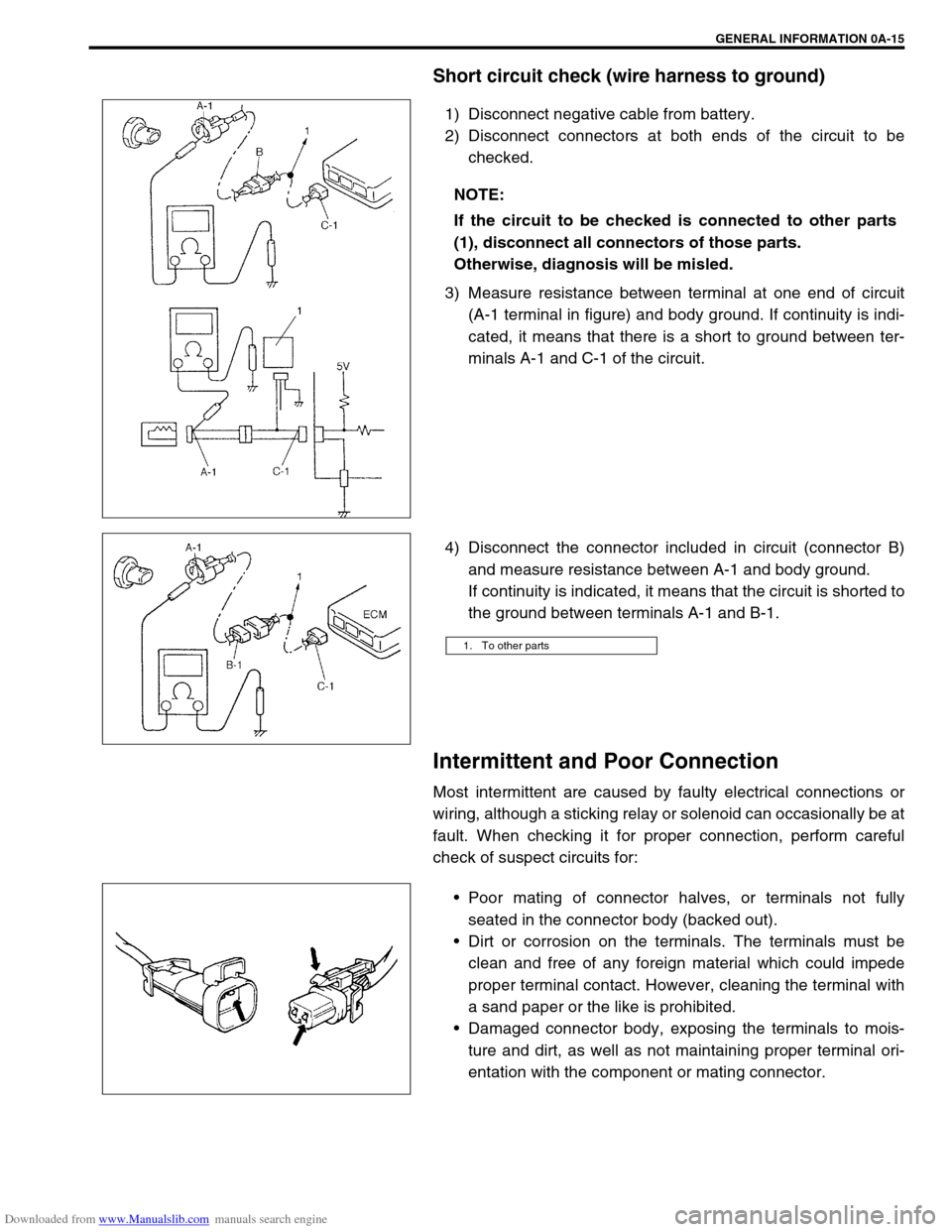
Short circuit check (wire harness to ground)
1) Disconnect negative cable from battery.
2) Disconnect connectors at both ends of the circuit to be
checked.
3) Measure resistance between terminal at one end of circuit
(A-1 terminal in figure) and body ground. If continuity is indi-
cated, it means that there is a short to ground between ter-
minals A-1 and C-1 of the circuit.
4) Disconnect the connector included in circuit (connector B)
and measure resistance between A-1 and body ground.
If continuity is indicated, it means that the circuit is shorted to
the ground between terminals A-1 and B-1.
Intermittent and Poor Connection
Most intermittent are caused by faulty electrical connections or
wiring, although a sticking relay or solenoid can occasionally be at
fault. When checking it for proper connection, perform careful
check of suspect circuits for:
Poor mating of connector halves, or terminals not fully
seated in the connector body (backed out).
Dirt or corrosion on the terminals. The terminals must be
clean and free of any foreign material which could impede
proper terminal contact. However, cleaning the terminal with
a sand paper or the like is prohibited.
Damaged connector body, exposing the terminals to mois-
ture and dirt, as well as not maintaining proper terminal ori-
entation with the component or mating connector. NOTE:
If the circuit to be checked is connected to other parts
(1), disconnect all connectors of those parts.
Otherwise, diagnosis will be misled.
1. To other parts
Page 21 of 687
Downloaded from www.Manualslib.com manuals search engine 0A-16 GENERAL INFORMATION
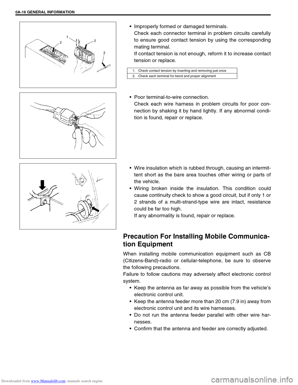
Improperly formed or damaged terminals.
Check each connector terminal in problem circuits carefully
to ensure good contact tension by using the corresponding
mating terminal.
If contact tension is not enough, reform it to increase contact
tension or replace.
Poor terminal-to-wire connection.
Check each wire harness in problem circuits for poor con-
nection by shaking it by hand lightly. If any abnormal condi-
tion is found, repair or replace.
Wire insulation which is rubbed through, causing an intermit-
tent short as the bare area touches other wiring or parts of
the vehicle.
Wiring broken inside the insulation. This condition could
cause continuity check to show a good circuit, but if only 1 or
2 strands of a multi-strand-type wire are intact, resistance
could be far too high.
If any abnormality is found, repair or replace.
Precaution For Installing Mobile Communica-
tion Equipment
When installing mobile communication equipment such as CB
(Citizens-Band)-radio or cellular-telephone, be sure to observe
the following precautions.
Failure to follow cautions may adversely affect electronic control
system.
Keep the antenna as far away as possible from the vehicle’s
electronic control unit.
Keep the antenna feeder more than 20 cm (7.9 in) away from
electronic control unit and its wire harnesses.
Do not run the antenna feeder parallel with other wire har-
nesses.
Confirm that the antenna and feeder are correctly adjusted.
1. Check contact tension by inserting and removing just once
2. Check each terminal for bend and proper alignment
Page 24 of 687
Downloaded from www.Manualslib.com manuals search engine GENERAL INFORMATION 0A-19
Vehicle Lifting Points
When Using Frame Contact Hoist
WARNING:
Before applying hoist to underbody, always take vehicle balance throughout service into consider-
ation. Vehicle balance on hoist may change depending on what part to be removed.
Before lifting up the vehicle, check to be sure that end of hoist arm is not in contact with brake pipe,
fuel pipe, bracket or any other part.
When using frame contact hoist, apply hoist as shown (right and left at the same position). Lift up
the vehicle till 4 tires are a little off the ground and make sure that the vehicle will not fall off by try-
ing to move vehicle body in both ways. Work can be started only after this confirmation.
Make absolutely sure to lock hoist after vehicle is hoisted up.
1. Front lifting point
2. Rear lifting point
3. Front
Page 25 of 687
Downloaded from www.Manualslib.com manuals search engine 0A-20 GENERAL INFORMATION
When Using Floor Jack
In raising front or rear vehicle end off the floor by jacking, be sure
to put the jack against the center portion of the front axle housing
(1) or rear axle housing (2).
To perform service with either front or rear vehicle end jacked up,
be sure to place safety stands (1) under chassis frame so that
body is securely supported. And then check to ensure that chas-
sis frame does not slide on safety stands (1) and the vehicle is
held stable for safety’s sake. WARNING:
If the vehicle to be jacked up only at the front or rear end,
be sure to block the wheels on ground in order to ensure
safety.
After the vehicle is jacked up, be sure to support it on
stands. It is extremely dangerous to do any work on the
vehicle raised on jack alone.
CAUTION:
Never apply jack against suspension parts (i.e., stabi-
lizer, etc.) or vehicle floor, or it may get deformed.
[A]: Front
[B]: Rear
Page 27 of 687

Downloaded from www.Manualslib.com manuals search engine 0A-22 GENERAL INFORMATION
LLH
LSPVLeft Hand
Load Sensing Proportioning Valve
TTBI
TCC
TCM
TP Sensor
TVV
TWC
2WDThrottle Body Fuel Injection
(Single-Point Fuel Injection, SPI)
Torque Converter Clutch
Transmission Control Module
(A/T Controller, A/T Control Mod-
ule)
Throttle Position Sensor
Thermal Vacuum Valve
(Thermal Vacuum Switching Valve,
TVSV, Bimetal Vacuum Switching
Valve, BVSV)
Three Way Catalytic Converter
(Three Way Catalyst)
2 Wheel Drive MMAF Sensor
MAP Sensor
Max
MFI
Min
MIL
M/TMass Air Flow Sensor
(Air Flow Sensor, AFS, Air Flow
Meter, AFM)
Manifold Absolute Pressure
Sensor (Pressure Sensor, PS)
Maximum
Multiport Fuel Injection
(Multipoint Fuel Injection)
Minimum
Malfunction Indicator Lamp
(“CHECK ENGINE” Light)
Manual Transmission
N NOx Nitrogen Oxides VVIN
VSSVehicle Identification Number
Vehicle Speed Sensor
OOBD
O/D
OHCOn-Board Diagnostic System
(Self-Diagnosis Function)
Overdrive
Over Head CamshaftWWU-OC
WU-TWCWarm Up Oxidation Catalytic
Converter
Warm Up Three Way Catalytic
Converter
PPNP
P/S
PSP Switch
PCM
PCVPark/Neutral Position
Power Steering
Power Steering Pressure Switch
(P/S Pressure Switch)
Powertrain Control Module
Positive Crankcase Ventilation
R RH Right Hand
SSAE
SDM
SFI
SOHCSociety of Automotive Engineers
Sensing and Diagnostic Module
(Air bag controller, Air bag control
module)
Sequential Multiport Fuel Injection
Single Over Head Camshaft
Page 36 of 687
Downloaded from www.Manualslib.com manuals search engine MAINTENANCE AND LUBRICATION 0B-5
Maintenance Service
Engine
Drive Belt
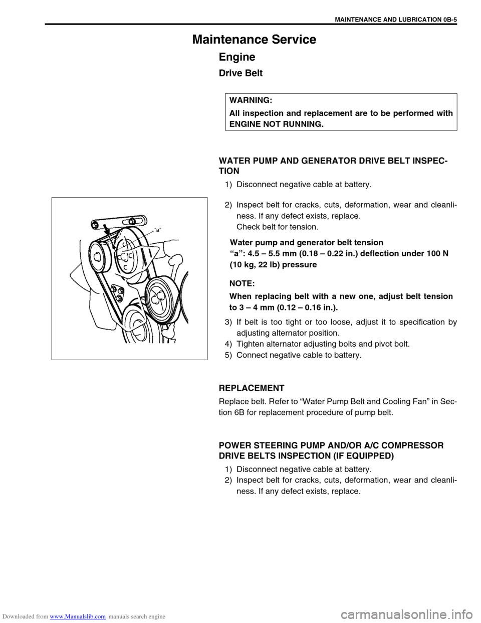
WATER PUMP AND GENERATOR DRIVE BELT INSPEC-
TION
1) Disconnect negative cable at battery.
2) Inspect belt for cracks, cuts, deformation, wear and cleanli-
ness. If any defect exists, replace.
Check belt for tension.
Water pump and generator belt tension
“a”: 4.5 – 5.5 mm (0.18 – 0.22 in.) deflection under 100 N
(10 kg, 22 lb) pressure
3) If belt is too tight or too loose, adjust it to specification by
adjusting alternator position.
4) Tighten alternator adjusting bolts and pivot bolt.
5) Connect negative cable to battery.
REPLACEMENT
Replace belt. Refer to “Water Pump Belt and Cooling Fan” in Sec-
tion 6B for replacement procedure of pump belt.
POWER STEERING PUMP AND/OR A/C COMPRESSOR
DRIVE BELTS INSPECTION (IF EQUIPPED)
1) Disconnect negative cable at battery.
2) Inspect belt for cracks, cuts, deformation, wear and cleanli-
ness. If any defect exists, replace. WARNING:
All inspection and replacement are to be performed with
ENGINE NOT RUNNING.
NOTE:
When replacing belt with a new one, adjust belt tension
to 3 – 4 mm (0.12 – 0.16 in.).
Page 37 of 687
Downloaded from www.Manualslib.com manuals search engine 0B-6 MAINTENANCE AND LUBRICATION
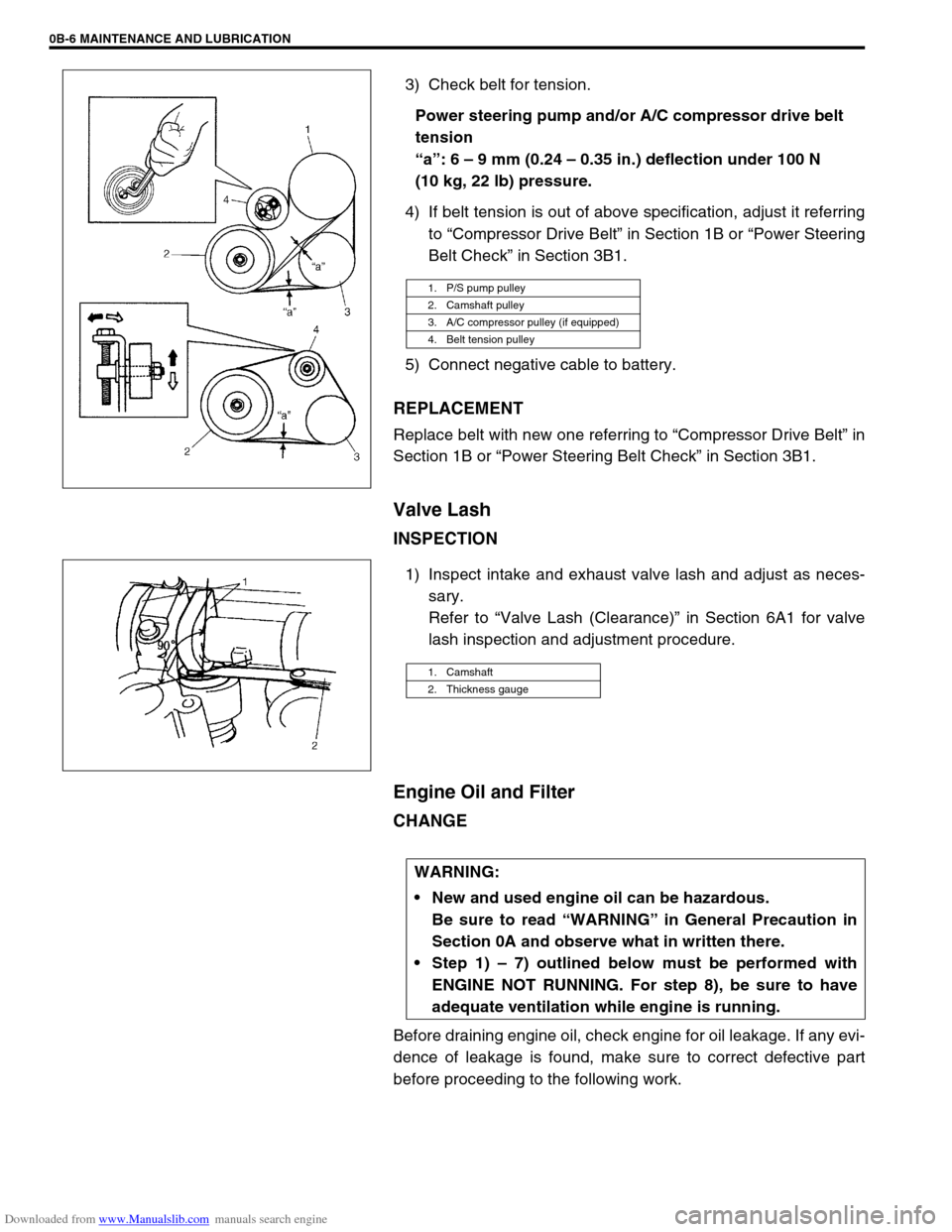
3) Check belt for tension.
Power steering pump and/or A/C compressor drive belt
tension
“a”: 6 – 9 mm (0.24 – 0.35 in.) deflection under 100 N
(10 kg, 22 lb) pressure.
4) If belt tension is out of above specification, adjust it referring
to “Compressor Drive Belt” in Section 1B or “Power Steering
Belt Check” in Section 3B1.
5) Connect negative cable to battery.
REPLACEMENT
Replace belt with new one referring to “Compressor Drive Belt” in
Section 1B or “Power Steering Belt Check” in Section 3B1.
Valve Lash
INSPECTION
1) Inspect intake and exhaust valve lash and adjust as neces-
sary.
Refer to “Valve Lash (Clearance)” in Section 6A1 for valve
lash inspection and adjustment procedure.
Engine Oil and Filter
CHANGE
Before draining engine oil, check engine for oil leakage. If any evi-
dence of leakage is found, make sure to correct defective part
before proceeding to the following work.
1. P/S pump pulley
2. Camshaft pulley
3. A/C compressor pulley (if equipped)
4. Belt tension pulley
1. Camshaft
2. Thickness gauge
WARNING:
New and used engine oil can be hazardous.
Be sure to read “WARNING” in General Precaution in
Section 0A and observe what in written there.
Step 1) – 7) outlined below must be performed with
ENGINE NOT RUNNING. For step 8), be sure to have
adequate ventilation while engine is running.
Page 39 of 687
Downloaded from www.Manualslib.com manuals search engine 0B-8 MAINTENANCE AND LUBRICATION
6) Replenish oil until oil level is brought to FULL level mark on
dipstick. (oil pan and oil filter capacity). The filler inlet is at
the top of the cylinder head cover.
It is recommended to use engine oil of SE, SF, SG, SH, SJ or
SL grade.
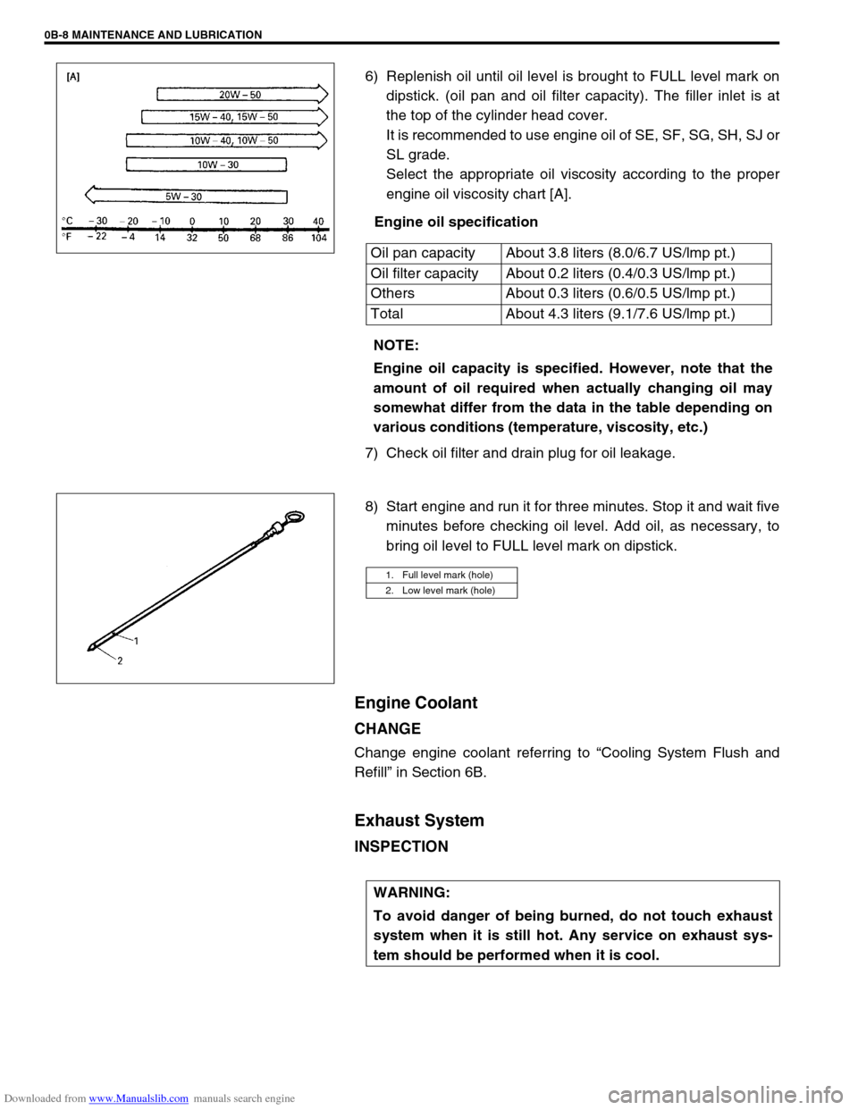
Select the appropriate oil viscosity according to the proper
engine oil viscosity chart [A].
Engine oil specification
7) Check oil filter and drain plug for oil leakage.
8) Start engine and run it for three minutes. Stop it and wait five
minutes before checking oil level. Add oil, as necessary, to
bring oil level to FULL level mark on dipstick.
Engine Coolant
CHANGE
Change engine coolant referring to “Cooling System Flush and
Refill” in Section 6B.
Exhaust System
INSPECTION
Oil pan capacity About 3.8 liters (8.0/6.7 US/lmp pt.)
Oil filter capacity About 0.2 liters (0.4/0.3 US/lmp pt.)
Others About 0.3 liters (0.6/0.5 US/lmp pt.)
Total About 4.3 liters (9.1/7.6 US/lmp pt.)
NOTE:
Engine oil capacity is specified. However, note that the
amount of oil required when actually changing oil may
somewhat differ from the data in the table depending on
various conditions (temperature, viscosity, etc.)
1. Full level mark (hole)
2. Low level mark (hole)
WARNING:
To avoid danger of being burned, do not touch exhaust
system when it is still hot. Any service on exhaust sys-
tem should be performed when it is cool.