Page 418 of 687
Downloaded from www.Manualslib.com manuals search engine ENGINE GENERAL INFORMATION AND DIAGNOSIS 6-61
DTC P0133 Heated Oxygen Sensor (HO2S) Circuit Slow Response (Sensor-1)
WIRING DIAGRAM
Refer to DTC P0130 section.
CIRCUIT DESCRIPTION
Fig. 1
DTC CONFIRMATION PROCEDURE
Refer to DTC P0130 section.
INSPECTION
DTC DETECTING CONDITION POSSIBLE CAUSE
When running at specified idle speed after engine warmed up and
running at specified vehicle speed, response time (time to change
from lean to rich or from rich to lean) of HO2S-1 output voltage is
about 1 sec. at minimum or average time of 1 cycle is 5 sec. at
minimum. See. Fig. 1
✱
✱✱ ✱2 driving cycle detection logic, Monitoring once / 1 driving.Heated oxygen sensor-1 malfunction
Step Action Yes No
1Was “Engine Diag. Flow Table” performed? Go to Step 2. Go to “Engine Diag. Flow
Table”.
2 Is there DTC(s) other than HO2S-1 (DTC
P0133)?Go to applicable DTC
Diag. Flow Table.Replace HO2S-1.
Page 429 of 687

Downloaded from www.Manualslib.com manuals search engine 6-72 ENGINE GENERAL INFORMATION AND DIAGNOSIS
DTC P0300 Random Misfire Detected (Misfire Detected at 2 or More Cylinders)
DTC P0301 Cylinder 1 Misfire Detected
DTC P0302 Cylinder 2 Misfire Detected
DTC P0303 Cylinder 3 Misfire Detected
DTC P0304 Cylinder 4 Misfire Detected
CIRCUIT DESCRIPTION
ECM monitors crankshaft revolution speed and engine speed via the crankshaft position sensor and cylinder No.
via the camshaft position sensor. Then it calculates the change in the crankshaft revolution speed and from how
many times such change occurred in every 200 or 1000 engine revolutions, it detects occurrence of misfire.
When ECM detects a misfire (misfire rate per 200 revolutions) which can cause overheat and damage to the
three way catalytic converter, it makes the malfunction indicator lamp (MIL) flash as long as misfire occurs at
that rate.
After that, however, when the misfire rate drops, MIL remains ON until it has been judged as normal 3 times
under the same driving conditions.
Also, when ECM detects a misfire (misfire rate per 1000 revolutions) which will not cause damage to three way
catalytic converter but can cause exhaust emission to be deteriorated, it makes MIL light according to the 2 driv-
ing cycle detection logic.
1. Ignition coil assembly (for No.1 and No.4 cylinder)
2. Ignition coil assembly (for No.2 and No.3 cylinder)
3. Fuel injector
4. CKP sensor
5. CMP sensor
Page 645 of 687

Downloaded from www.Manualslib.com manuals search engine 6E-40 ENGINE AND EMISSION CONTROL SYSTEM
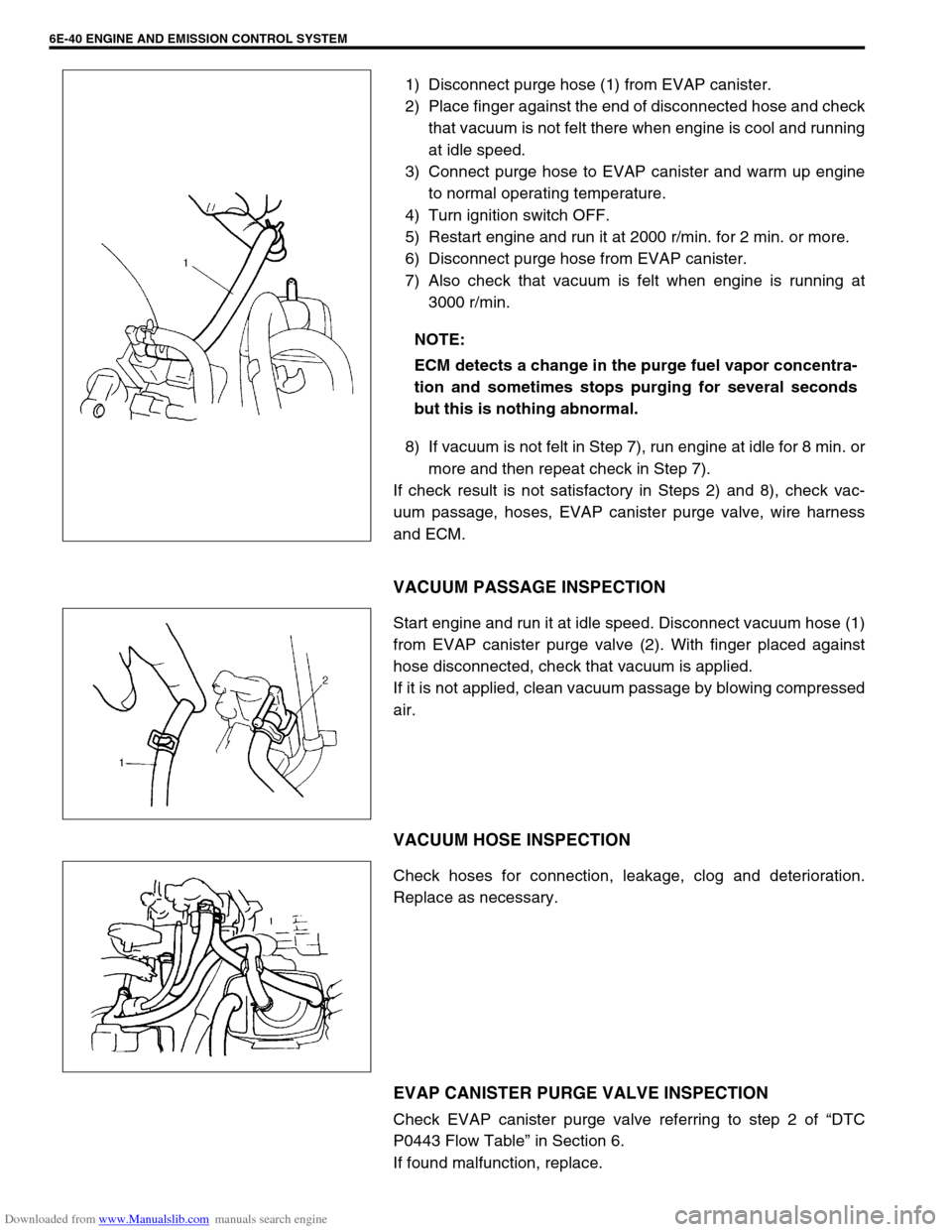
1) Disconnect purge hose (1) from EVAP canister.
2) Place finger against the end of disconnected hose and check
that vacuum is not felt there when engine is cool and running
at idle speed.
3) Connect purge hose to EVAP canister and warm up engine
to normal operating temperature.
4) Turn ignition switch OFF.
5) Restart engine and run it at 2000 r/min. for 2 min. or more.
6) Disconnect purge hose from EVAP canister.
7) Also check that vacuum is felt when engine is running at
3000 r/min.
8) If vacuum is not felt in Step 7), run engine at idle for 8 min. or
more and then repeat check in Step 7).
If check result is not satisfactory in Steps 2) and 8), check vac-
uum passage, hoses, EVAP canister purge valve, wire harness
and ECM.
VACUUM PASSAGE INSPECTION
Start engine and run it at idle speed. Disconnect vacuum hose (1)
from EVAP canister purge valve (2). With finger placed against
hose disconnected, check that vacuum is applied.
If it is not applied, clean vacuum passage by blowing compressed
air.
VACUUM HOSE INSPECTION
Check hoses for connection, leakage, clog and deterioration.
Replace as necessary.
EVAP CANISTER PURGE VALVE INSPECTION
Check EVAP canister purge valve referring to step 2 of “DTC
P0443 Flow Table” in Section 6.
If found malfunction, replace.NOTE:
ECM detects a change in the purge fuel vapor concentra-
tion and sometimes stops purging for several seconds
but this is nothing abnormal.