2005 SUZUKI JIMNY Steering bleed
[x] Cancel search: Steering bleedPage 152 of 687

Downloaded from www.Manualslib.com manuals search engine POWER STEERING (P/S) SYSTEM (If equipped) 3B1-21
Tightening Torque Specifications
Required Service Materials
Special Tools
Fastening partTightening torque
Nm kg-m lb-ft
Tension pulley bolt 25 2.5 18.0
Oil pump mounting bolt 25 2.5 18.5
Oil pump high pressure union bolt 60 6.0 43.5
Oil pump cover bolts 28 2.8 20.0
Pressure switch 28 2.8 20.0
Suction connector bolt 12 1.2 8.5
Power steering gear box mounting bolt
and nuts80 8.0 58.0
Gear box high pressure union bolt 35 3.5 25.5
Pitman arm mounting nut 135 13.5 98.0
Steering shaft joint bolt 25 2.5 18.5
Plug 60 6.0 43.5
MaterialRecommended SUZUKI product
(Part Number)Use
Power steering
fluidAn equivalent of DEXRON
®-II,
DEXRON
®-IIE or DEXRON®-III.To fill P/S fluid reservoir
Parts lubrication when installing
Lithium greaseSUPER GREASE (A)
(99000-25010)Oil seal lip of P/S pump pulley shaft
09915-77411 09915-77420 09944-18211 09945-35010
Oil pressure gauge Oil pressure gauge
attachment & hose setTorque check socket Air bleeding hose set
Page 249 of 687

Downloaded from www.Manualslib.com manuals search engine 3F-6 WHEELS AND TIRES
Maintenance and Minor Adjustments
Wheel and Tire
Wheel repairs that use welding, heating, or peening are not approved. All damaged wheels should be replaced.
Studs
If a broken stud is found, see Section 3E (rear) or Section 3D (front) for Note and Replacement procedure.
Matched tires and wheels
(For vehicle equipped with steel wheels)
Tires and wheels are matchmounted at the assembly plant.
This means that the radially stiffest part of the tire, or “high spot”,
is matched to the smallest radius or “low spot” of the wheel.
This is done to provide the smoothest possible ride.
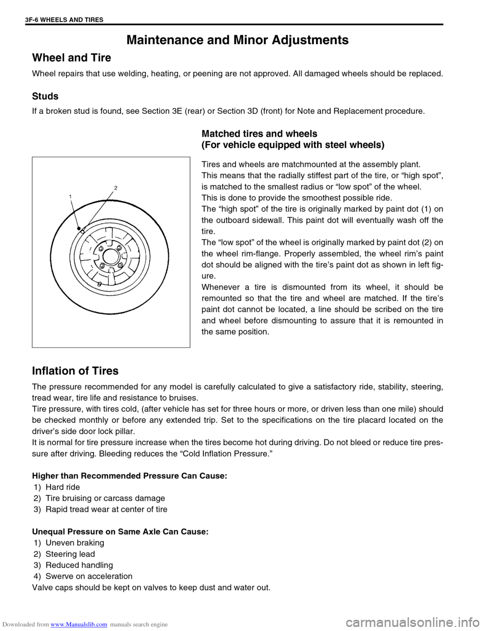
The “high spot” of the tire is originally marked by paint dot (1) on
the outboard sidewall. This paint dot will eventually wash off the
tire.
The “low spot” of the wheel is originally marked by paint dot (2) on
the wheel rim-flange. Properly assembled, the wheel rim’s paint
dot should be aligned with the tire’s paint dot as shown in left fig-
ure.
Whenever a tire is dismounted from its wheel, it should be
remounted so that the tire and wheel are matched. If the tire’s
paint dot cannot be located, a line should be scribed on the tire
and wheel before dismounting to assure that it is remounted in
the same position.
Inflation of Tires
The pressure recommended for any model is carefully calculated to give a satisfactory ride, stability, steering,
tread wear, tire life and resistance to bruises.
Tire pressure, with tires cold, (after vehicle has set for three hours or more, or driven less than one mile) should
be checked monthly or before any extended trip. Set to the specifications on the tire placard located on the
driver’s side door lock pillar.
It is normal for tire pressure increase when the tires become hot during driving. Do not bleed or reduce tire pres-
sure after driving. Bleeding reduces the “Cold Inflation Pressure.”
Higher than Recommended Pressure Can Cause:
1) Hard ride
2) Tire bruising or carcass damage
3) Rapid tread wear at center of tire
Unequal Pressure on Same Axle Can Cause:
1) Uneven braking
2) Steering lead
3) Reduced handling
4) Swerve on acceleration
Valve caps should be kept on valves to keep dust and water out.
Page 264 of 687

Downloaded from www.Manualslib.com manuals search engine BRAKES 5-3
General Description
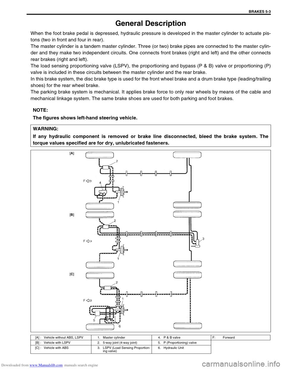
When the foot brake pedal is depressed, hydraulic pressure is developed in the master cylinder to actuate pis-
tons (two in front and four in rear).
The master cylinder is a tandem master cylinder. Three (or two) brake pipes are connected to the master cylin-
der and they make two independent circuits. One connects front brakes (right and left) and the other connects
rear brakes (right and left).
The load sensing proportioning valve (LSPV), the proportioning and bypass (P & B) valve or proportioning (P)
valve is included in these circuits between the master cylinder and the rear brake.
In this brake system, the disc brake type is used for the front wheel brake and a drum brake type (leading/trailing
shoes) for the rear wheel brake.
The parking brake system is mechanical. It applies brake force to only rear wheels by means of the cable and
mechanical linkage system. The same brake shoes are used for both parking and foot brakes.
NOTE:
The figures shows left-hand steering vehicle.
WARNING:
If any hydraulic component is removed or brake line disconnected, bleed the brake system. The
torque values specified are for dry, unlubricated fasteners.
[A] : Vehicle without ABS, LSPV 1. Master cylinder 4. P & B valve F: Forward
[B] : Vehicle with LSPV 2. 5-way joint (4-way joint) 5. P (Proportioning) valve
[C] : Vehicle with ABS 3. LSPV (Load Sensing Proportion-
ing valve)6. Hydraulic Unit
Page 267 of 687

Downloaded from www.Manualslib.com manuals search engine 5-6 BRAKES
Excessive pedal travel
(Pedal stroke too
large)Partial brake system failure Check brake systems and repair as
necessary.
Insufficient fluid in master cylinder reservoirs Fill reservoirs with approved brake
fluid.
Check for leaks and air in brake
systems.
Check warning light. Bleed system
if required.
Air in system (pedal soft/spongy) Bleed system.
Rear brake system not adjusted (malfunctioning
auto adjusting mechanism)Repair auto adjusting mechanism.
Adjust rear brakes.
Bent brake shoes Replace brake shoes.
Worn rear brake shoes Replace brake shoes.
Dragging brakes (A
very light drag is
present in all disc
brakes immediately
after pedal is released)Master cylinder pistons not returning correctly Repair master cylinder.
Restricted brake tubes or hoses Check for soft hoses or damaged
tubes and replace with new hoses
and/or new brake tubes.
Incorrect parking brake adjustment on rear
brakesCheck and adjust to correct specifi-
cations.
Weakened or broken return springs in the brake Replace.
Sluggish parking-brake cables or linkage Repair or replace.
Wheel cylinder or caliper piston sticking Repair as necessary.
Malfunctioning ABS, if equipped with ABS Check system and replace as nec-
essary.
Pedal pulsation (Pedal
pulsates when
depressed for brak-
ing.) Damaged or loose wheel bearings Replace wheel bearings.
Distorted steering knuckle or rear axle shafts Replace knuckle or rear axle shaft.
Excessive disc lateral runout Check per instructions. If not within
specifications, replace or machine
the disc.
Parallelism not within specifications Check per instructions. If not with
specifications, replace or machine
the disc.
Rear drums out of round. Check runout.
Repair or replace drum as neces-
sary.
Braking noise
Glazed shoe linings, or foreign matters stuck to
liningsRepair or replace brake shoe.
Worn or distorted shoe linings Replace brake shoe (or pad).
Loose front wheel bearings Replace wheel bearing.
Distorted backing plates or loose mounting
boltsReplace or retighten securing bolts.
Brake warning light
turns on after engine
startParking brake applied Release parking brake and check
that brake warning light turns off.
Insufficient amount of brake fluid Add brake fluid.
Brake fluid leaking from brake line Investigate leaky point, correct it
and add brake fluid.
Brake warning light circuit faulty Repair circuit. Condition Possible Cause Correction
Page 270 of 687

Downloaded from www.Manualslib.com manuals search engine BRAKES 5-9
Excessive Pedal Travel Check
1) Start engine.
2) Depress brake pedal a few times.
3) With brake pedal depressed with approximately 30 kg (66
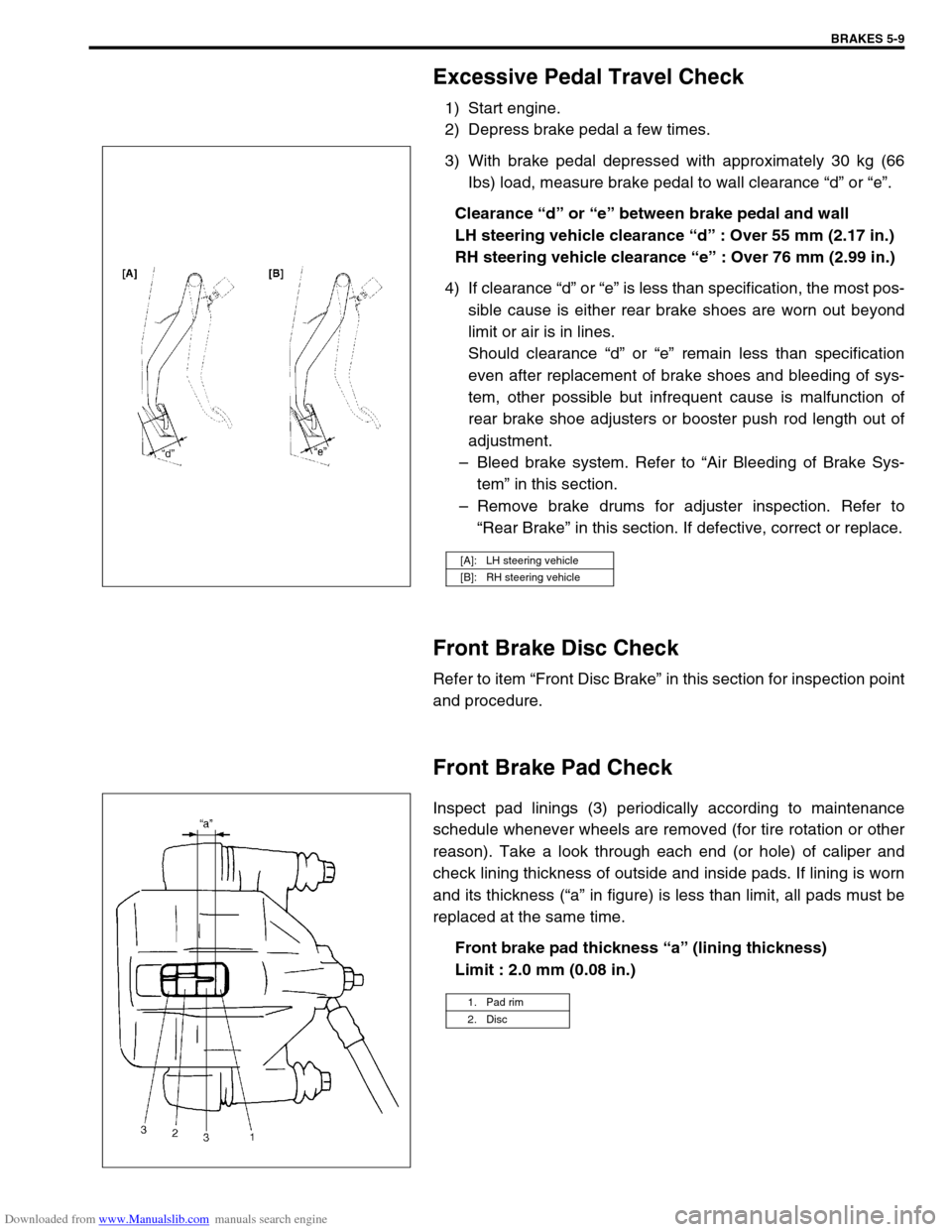
Ibs) load, measure brake pedal to wall clearance “d” or “e”.
Clearance “d” or “e” between brake pedal and wall
LH steering vehicle clearance “d” : Over 55 mm (2.17 in.)
RH steering vehicle clearance “e” : Over 76 mm (2.99 in.)
4) If clearance “d” or “e” is less than specification, the most pos-
sible cause is either rear brake shoes are worn out beyond
limit or air is in lines.
Should clearance “d” or “e” remain less than specification
even after replacement of brake shoes and bleeding of sys-
tem, other possible but infrequent cause is malfunction of
rear brake shoe adjusters or booster push rod length out of
adjustment.
–Bleed brake system. Refer to “Air Bleeding of Brake Sys-
tem” in this section.
–Remove brake drums for adjuster inspection. Refer to
“Rear Brake” in this section. If defective, correct or replace.
Front Brake Disc Check
Refer to item “Front Disc Brake” in this section for inspection point
and procedure.
Front Brake Pad Check
Inspect pad linings (3) periodically according to maintenance
schedule whenever wheels are removed (for tire rotation or other
reason). Take a look through each end (or hole) of caliper and
check lining thickness of outside and inside pads. If lining is worn
and its thickness (“a” in figure) is less than limit, all pads must be
replaced at the same time.
Front brake pad thickness “a” (lining thickness)
Limit : 2.0 mm (0.08 in.)
[A]: LH steering vehicle
[B]: RH steering vehicle
1. Pad rim
2. Disc
Page 311 of 687

Downloaded from www.Manualslib.com manuals search engine 5-50 BRAKES
REMOVAL
1) Raise, suitably support vehicle. Remove wheel if necessary.
2) Clean dirt and foreign material from both hose end or pipe end fittings. Remove brake hose and pipe.
INSTALLATION
1) Install brake hose and pipe by reversing removal procedure, noting the following points.
For installation, make sure that steering wheel is in straightforward position and hose has no twist or kink.
Check to make sure that hose doesn’t contact any part of suspension, both in extreme right and extreme left
turn conditions. If it does at any point, remove and correct. Fill and maintain brake fluid level in reservoir.
Bleed brake system.
2) Perform brake test and check installed part for fluid leakage.