Page 490 of 687

Downloaded from www.Manualslib.com manuals search engine ENGINE MECHANICAL (M13 ENGINE) 6A1-9
Valve Lash (Clearance)
1) Remove negative cable at battery.
2) Remove cylinder head cover referring to “Cylinder Head
Cover” in this section.
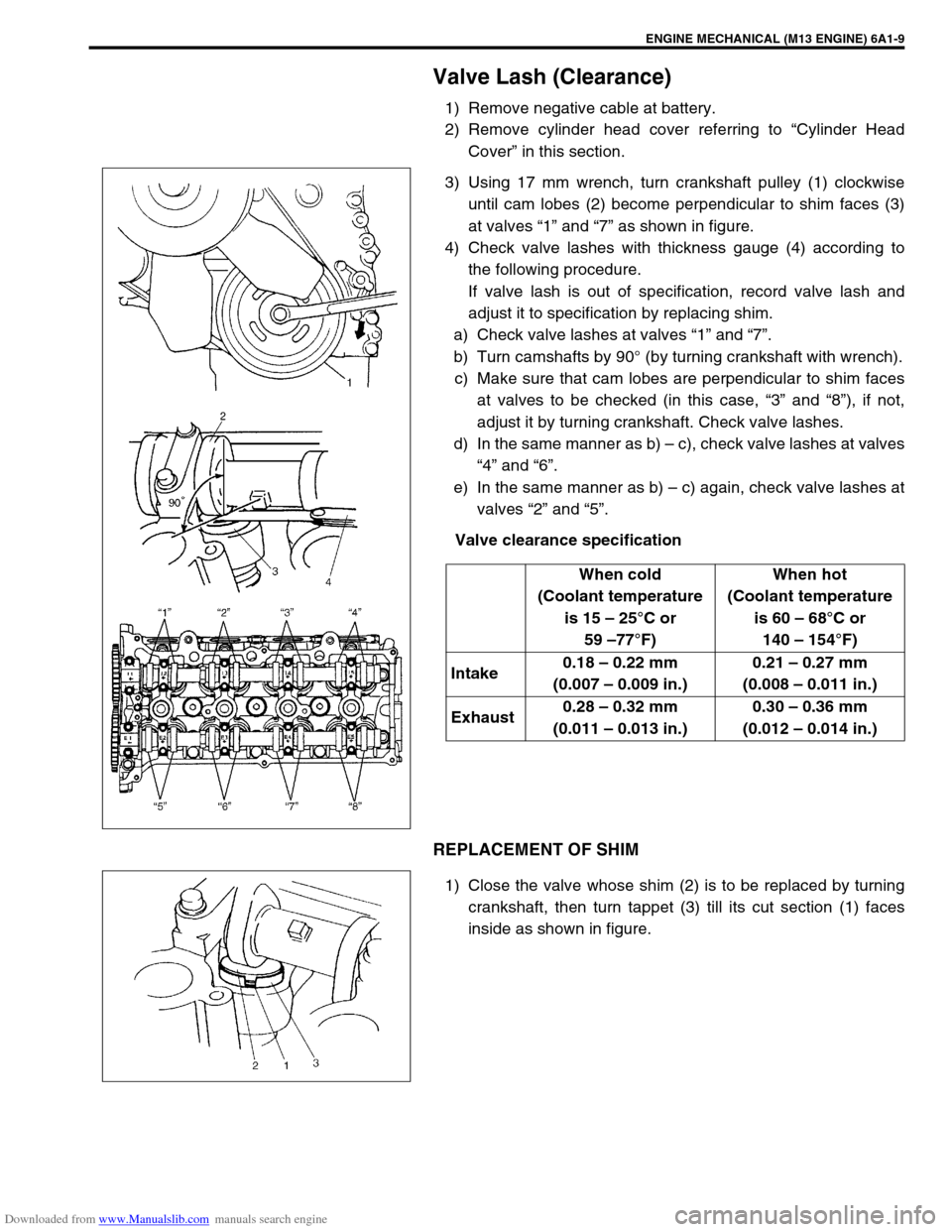
3) Using 17 mm wrench, turn crankshaft pulley (1) clockwise
until cam lobes (2) become perpendicular to shim faces (3)
at valves “1” and “7” as shown in figure.
4) Check valve lashes with thickness gauge (4) according to
the following procedure.
If valve lash is out of specification, record valve lash and
adjust it to specification by replacing shim.
a) Check valve lashes at valves “1” and “7”.
b) Turn camshafts by 90° (by turning crankshaft with wrench).
c) Make sure that cam lobes are perpendicular to shim faces
at valves to be checked (in this case, “3” and “8”), if not,
adjust it by turning crankshaft. Check valve lashes.
d) In the same manner as b) – c), check valve lashes at valves
“4” and “6”.
e) In the same manner as b) – c) again, check valve lashes at
valves “2” and “5”.
Valve clearance specification
REPLACEMENT OF SHIM
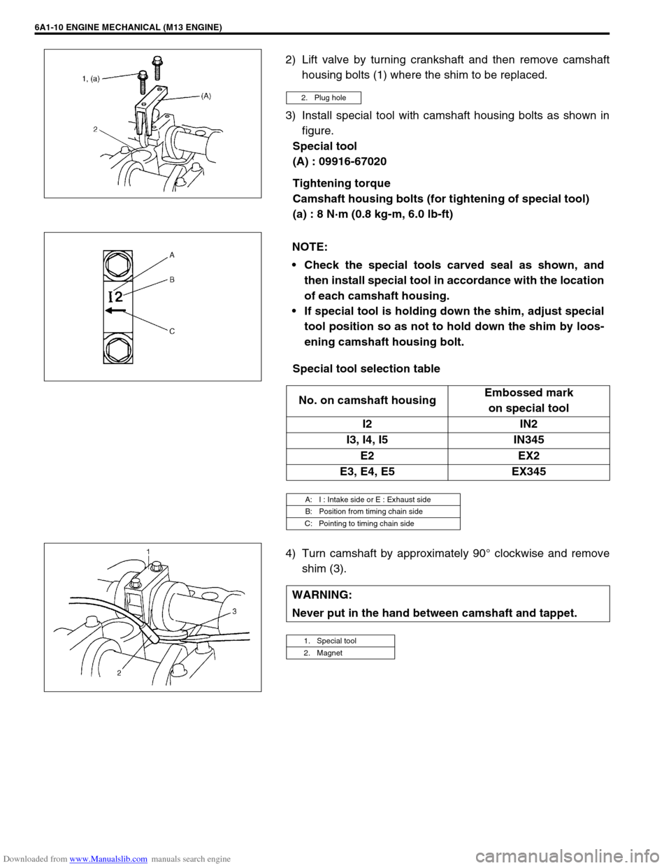
1) Close the valve whose shim (2) is to be replaced by turning
crankshaft, then turn tappet (3) till its cut section (1) faces
inside as shown in figure.When cold
(Coolant temperature
is 15 – 25°C or
59 –77°F)When hot
(Coolant temperature
is 60 – 68°C or
140 – 154°F)
Intake0.18 – 0.22 mm
(0.007 – 0.009 in.)0.21 – 0.27 mm
(0.008 – 0.011 in.)
Exhaust0.28 – 0.32 mm
(0.011 – 0.013 in.)0.30 – 0.36 mm
(0.012 – 0.014 in.)
Page 491 of 687

Downloaded from www.Manualslib.com manuals search engine 6A1-10 ENGINE MECHANICAL (M13 ENGINE)
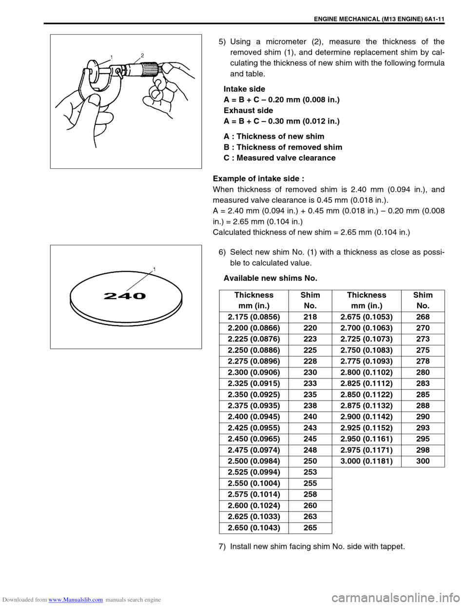
2) Lift valve by turning crankshaft and then remove camshaft
housing bolts (1) where the shim to be replaced.
3) Install special tool with camshaft housing bolts as shown in
figure.
Special tool
(A) : 09916-67020
Tightening torque
Camshaft housing bolts (for tightening of special tool)
(a) : 8 N·m (0.8 kg-m, 6.0 lb-ft)
Special tool selection table
4) Turn camshaft by approximately 90° clockwise and remove
shim (3).
2. Plug hole
NOTE:
Check the special tools carved seal as shown, and
then install special tool in accordance with the location
of each camshaft housing.
If special tool is holding down the shim, adjust special
tool position so as not to hold down the shim by loos-
ening camshaft housing bolt.
No. on camshaft housingEmbossed mark
on special tool
I2 IN2
I3, I4, I5 IN345
E2 EX2
E3, E4, E5 EX345
A: I : Intake side or E : Exhaust side
B: Position from timing chain side
C: Pointing to timing chain side
WARNING:
Never put in the hand between camshaft and tappet.
1. Special tool
2. Magnet
Page 492 of 687

Downloaded from www.Manualslib.com manuals search engine ENGINE MECHANICAL (M13 ENGINE) 6A1-11
5) Using a micrometer (2), measure the thickness of the
removed shim (1), and determine replacement shim by cal-
culating the thickness of new shim with the following formula
and table.
Intake side
A = B + C – 0.20 mm (0.008 in.)
Exhaust side
A = B + C – 0.30 mm (0.012 in.)
A : Thickness of new shim
B : Thickness of removed shim
C : Measured valve clearance
Example of intake side :
When thickness of removed shim is 2.40 mm (0.094 in.), and
measured valve clearance is 0.45 mm (0.018 in.).
A = 2.40 mm (0.094 in.) + 0.45 mm (0.018 in.) – 0.20 mm (0.008
in.) = 2.65 mm (0.104 in.)
Calculated thickness of new shim = 2.65 mm (0.104 in.)
6) Select new shim No. (1) with a thickness as close as possi-
ble to calculated value.
Available new shims No.
7) Install new shim facing shim No. side with tappet.
Thickness
mm (in.)Shim
No.Thickness
mm (in.)Shim
No.
2.175 (0.0856) 218 2.675 (0.1053) 268
2.200 (0.0866) 220 2.700 (0.1063) 270
2.225 (0.0876) 223 2.725 (0.1073) 273
2.250 (0.0886) 225 2.750 (0.1083) 275
2.275 (0.0896) 228 2.775 (0.1093) 278
2.300 (0.0906) 230 2.800 (0.1102) 280
2.325 (0.0915) 233 2.825 (0.1112) 283
2.350 (0.0925) 235 2.850 (0.1122) 285
2.375 (0.0935) 238 2.875 (0.1132) 288
2.400 (0.0945) 240 2.900 (0.1142) 290
2.425 (0.0955) 243 2.925 (0.1152) 293
2.450 (0.0965) 245 2.950 (0.1161) 295
2.475 (0.0974) 248 2.975 (0.1171) 298
2.500 (0.0984) 250 3.000 (0.1181) 300
2.525 (0.0994) 253
2.550 (0.1004) 255
2.575 (0.1014) 258
2.600 (0.1024) 260
2.625 (0.1033) 263
2.650 (0.1043) 265
Page 523 of 687
Downloaded from www.Manualslib.com manuals search engine 6A1-42 ENGINE MECHANICAL (M13 ENGINE)
Camshaft, Tappet and Shim
REMOVAL
1) Remove cylinder head cover and oil pan referring to “Cylin-
der Head Cover” and “Oil Pan and Oil Pump Strainer” in this
section.
2) Remove timing chain cover referring to “Timing Chain Cover”
in this section.
3) Remove timing chain referring to “Timing Chain and Chain
Tensioner” in this section.
4) Loosen camshaft housing bolts in such order as indicated in
figure and remove them.
5) Remove camshaft housings.
6) Remove intake and exhaust camshafts.
1. Intake camshaft 4. Tappet Tightening torque
2. Exhaust camshaft 5. Camshaft housing Apply engine oil to sliding surface of each part.
3. Shim
: Shim No. on it faces tappet side.6. Camshaft housing bolt
Page 524 of 687
Downloaded from www.Manualslib.com manuals search engine ENGINE MECHANICAL (M13 ENGINE) 6A1-43
7) Remove tappets (1) with shims (2).
INSPECTION
Cam Wear
Using a micrometer, measure cam height “a”. If measured height
is below its limit, replace camshaft.
Cam height “a” of camshaft
Camshaft Runout
Set camshaft between two “V” blocks, and measure its runout by
using a dial gauge.
If measured runout exceeds below limit, replace camshaft.
Camshaft runout limit
0.10 mm (0.0039 in.)
Camshaft Journal Wear
Check camshaft journals and camshaft housings for pitting,
scratches, wear or damage.
If any malcondition is found, replace camshaft or cylinder head
with housing. Never replace cylinder head without replacing
housings.
Standard Limit
Intake cam 44.919 – 45.079 mm
(1.768 – 1.775 in.)44.80 mm
(1.764 in.)
Exhaust cam 44.399 – 44.559 mm
(1.748 – 1.754 in.)44.28 mm
(1.743 in.)
Page 525 of 687

Downloaded from www.Manualslib.com manuals search engine 6A1-44 ENGINE MECHANICAL (M13 ENGINE)
Check clearance by using gauging plastic. Checking procedure is
as follows.
1) Clean housings and camshaft journals.
2) Remove all tappets with shims.
3) Install camshafts to cylinder head.
4) Place a piece of gauging plastic to full width of journal of
camshaft (parallel to camshaft).
5) Install camshaft housing.
6) Tighten camshaft housing bolts in such order as indicated in
figure a little at a time till they are tightened to specified
torque.
Tightening torque
Camshaft housing bolts (a) : 11 N·m (1.1 kg-m, 8.0 lb-ft)
7) Remove housing, and using scale (2) on gauging plastic (1)
envelop, measure gauging plastic width at its widest point.
Camshaft journal clearance
If measured camshaft journal clearance exceeds limit, measure
journal (housing) bore and outside diameter of camshaft journal.
Replace camshaft or cylinder head assembly whichever the dif-
ference from specification is greater.
Camshaft journal outside diameter [A]
Camshaft journal bore diameter [B] NOTE:
Do not rotate camshaft while gauging plastic is installed.
Standard Limit
0.045 – 0.087 mm
(0.0018 – 0.0034 in.)0.12 mm
(0.0047 in.)
Item Standard
No.126.934 – 26.955 mm
(1.0604 – 1.0612 in.)
Other22.934 – 22.955 mm
(0.9029 – 0.9037 in.)
Item Standard
No.127.000 – 27.021 mm
(1.0630 – 1.0638 in.)
Other23.000 – 23.021 mm
(0.9055 – 0.9063 in.)
Page 526 of 687
Downloaded from www.Manualslib.com manuals search engine ENGINE MECHANICAL (M13 ENGINE) 6A1-45
Wear of Tappet and Shim
Check tappet and shim for pitting, scratches or damage.
If any malcondition is found, replace.
Measure cylinder head bore and tappet outside diameter to deter-
mine cylinder head-to-tappet clearance. If clearance exceeds
limit, replace tappet or cylinder head.
Cylinder head to tappet clearance
Standard : 0.025 – 0.066 mm (0.0010 – 0.0026 in.)
Limit : 0.15 mm (0.0059 in.)
Tappet outside diameter [A]
Standard : 30.959 – 30.975 mm (1.2189 – 1.2195 in.)
Cylinder head tappet bore [B]
Standard : 31.000 – 31.025 mm (1.2205 – 1.2215 in.)
Page 527 of 687
Downloaded from www.Manualslib.com manuals search engine 6A1-46 ENGINE MECHANICAL (M13 ENGINE)
INSTALLATION
1) Install tappets and shims to cylinder head.
Apply engine oil around tappet and then install it to cylinder
head.
2) Install camshafts (1).
Apply engine oil to sliding surface of each camshaft and
camshaft journal then install them as shown in figure.
3) Install camshaft housing pins (1) as shown in figure.
4) Check position of camshaft housings.
Embossed marks are provided on each camshaft housing,
indicating position and direction for installation. Install hous-
ings as indicated by these marks. NOTE:
When installing shim, make sure to direct shim No. side
toward tappet.
NOTE:
Before installing camshafts, turn crankshaft until key
position faces upward. Refer to “Timing Chain and Chain
Tensioner”.
A. I : Intake side or E : Exhaust side
B. Position from timing chain side
C. Pointing to timing chain side