2005 SUZUKI JIMNY Pressure switch
[x] Cancel search: Pressure switchPage 79 of 687
![SUZUKI JIMNY 2005 3.G Service Workshop Manual Downloaded from www.Manualslib.com manuals search engine 1B-18 AIR CONDITIONING (OPTIONAL)
Terminal arrangement of ECM coupler (Viewed from harness side)
1. Blower fan motor 8. Compressor [A]: To “A SUZUKI JIMNY 2005 3.G Service Workshop Manual Downloaded from www.Manualslib.com manuals search engine 1B-18 AIR CONDITIONING (OPTIONAL)
Terminal arrangement of ECM coupler (Viewed from harness side)
1. Blower fan motor 8. Compressor [A]: To “A](/manual-img/20/7588/w960_7588-78.png)
Downloaded from www.Manualslib.com manuals search engine 1B-18 AIR CONDITIONING (OPTIONAL)
Terminal arrangement of ECM coupler (Viewed from harness side)
1. Blower fan motor 8. Compressor [A]: To “A/C” fuse (25A) in main fuse box
2. Dual pressure switch 9. Thermal switch [B]: To “HEATER” fuse (20A) in circuit fuse box
3. A/C switch 10. Main relay [C]: To “FI” fuse (15A) in main fuse box
4. A/C evaporator thermistor 11. Engine earth [D]: 4WD model
5. ECT sensor 12. Blower fan motor switch [E]: 2WD model
6. Condenser cooling fan motor relay 13. 4WD controller
7. Condenser cooling fan motor 14. ECM
Page 90 of 687
Downloaded from www.Manualslib.com manuals search engine AIR CONDITIONING (OPTIONAL) 1B-29
On-Vehicle Service
Service Precaution
When servicing air conditioning system, note the following instructions.
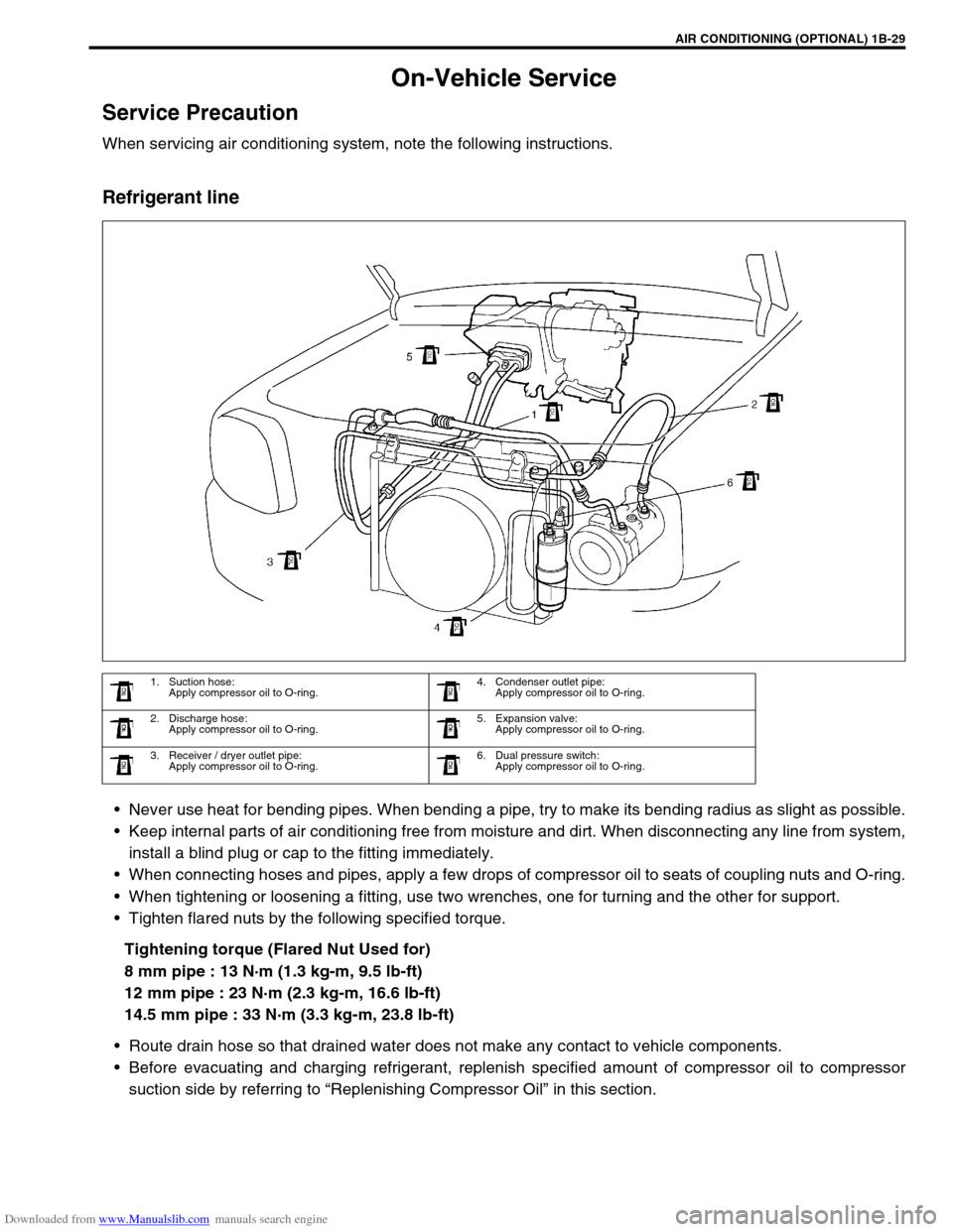
Refrigerant line
Never use heat for bending pipes. When bending a pipe, try to make its bending radius as slight as possible.
Keep internal parts of air conditioning free from moisture and dirt. When disconnecting any line from system,
install a blind plug or cap to the fitting immediately.
When connecting hoses and pipes, apply a few drops of compressor oil to seats of coupling nuts and O-ring.
When tightening or loosening a fitting, use two wrenches, one for turning and the other for support.
Tighten flared nuts by the following specified torque.
Tightening torque (Flared Nut Used for)
8 mm pipe : 13 N·m (1.3 kg-m, 9.5 lb-ft)
12 mm pipe : 23 N·m (2.3 kg-m, 16.6 lb-ft)
14.5 mm pipe : 33 N·m (3.3 kg-m, 23.8 lb-ft)
Route drain hose so that drained water does not make any contact to vehicle components.
Before evacuating and charging refrigerant, replenish specified amount of compressor oil to compressor
suction side by referring to “Replenishing Compressor Oil” in this section.
1. Suction hose:
Apply compressor oil to O-ring.4. Condenser outlet pipe:
Apply compressor oil to O-ring.
2. Discharge hose:
Apply compressor oil to O-ring.5. Expansion valve:
Apply compressor oil to O-ring.
3. Receiver / dryer outlet pipe:
Apply compressor oil to O-ring.6. Dual pressure switch:
Apply compressor oil to O-ring.
Page 99 of 687
Downloaded from www.Manualslib.com manuals search engine 1B-38 AIR CONDITIONING (OPTIONAL)
INSTALLATION
Reverse removal procedure for installation, and then note the fol-
lowing instructions.
Replenish specified amount of compressor oil to compressor
suction side by referring to “Replenishing Compressor Oil” in
this section.
Evacuate and charge refrigerant by referring to “Evacuation”
and “Charging” in this section.
Dual Pressure Switch
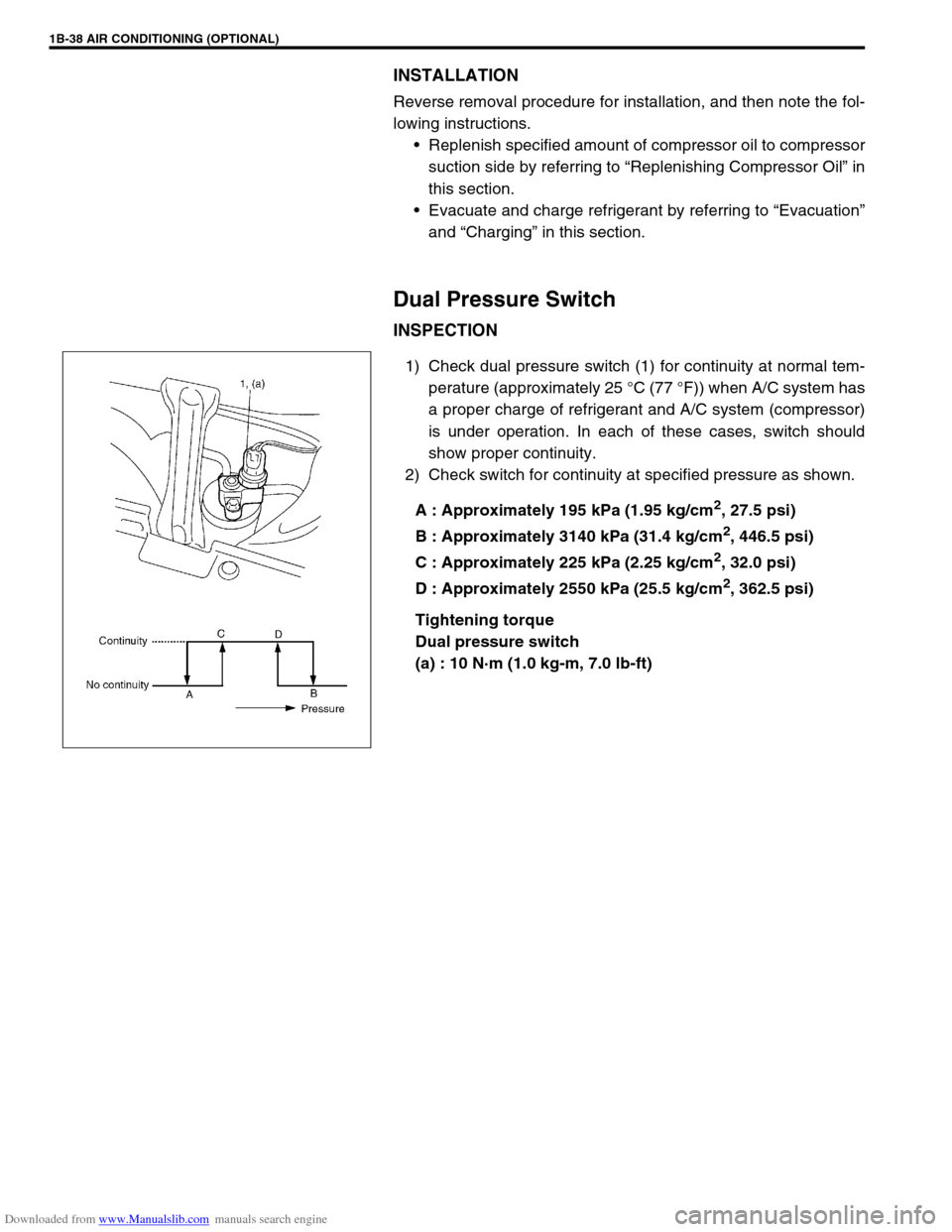
INSPECTION
1) Check dual pressure switch (1) for continuity at normal tem-
perature (approximately 25 °C (77 °F)) when A/C system has
a proper charge of refrigerant and A/C system (compressor)
is under operation. In each of these cases, switch should
show proper continuity.
2) Check switch for continuity at specified pressure as shown.
A : Approximately 195 kPa (1.95 kg/cm
2, 27.5 psi)
B : Approximately 3140 kPa (31.4 kg/cm
2, 446.5 psi)
C : Approximately 225 kPa (2.25 kg/cm
2, 32.0 psi)
D : Approximately 2550 kPa (25.5 kg/cm
2, 362.5 psi)
Tightening torque
Dual pressure switch
(a) : 10 N·m (1.0 kg-m, 7.0 lb-ft)
Page 107 of 687
Downloaded from www.Manualslib.com manuals search engine 1B-46 AIR CONDITIONING (OPTIONAL)
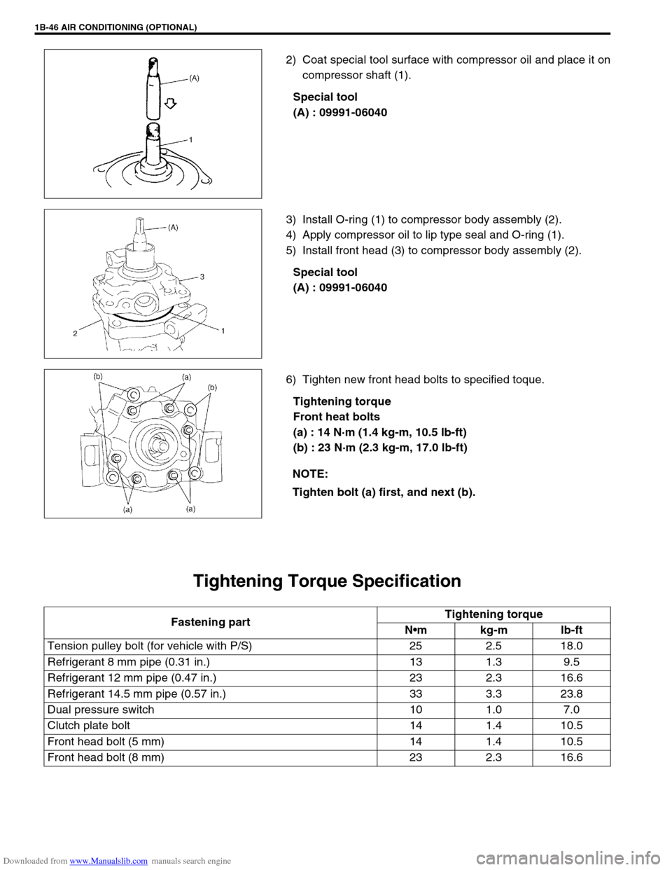
2) Coat special tool surface with compressor oil and place it on
compressor shaft (1).
Special tool
(A) : 09991-06040
3) Install O-ring (1) to compressor body assembly (2).
4) Apply compressor oil to lip type seal and O-ring (1).
5) Install front head (3) to compressor body assembly (2).
Special tool
(A) : 09991-06040
6) Tighten new front head bolts to specified toque.
Tightening torque
Front heat bolts
(a) : 14 N·m (1.4 kg-m, 10.5 lb-ft)
(b) : 23 N·m (2.3 kg-m, 17.0 lb-ft)
Tightening Torque Specification
NOTE:
Tighten bolt (a) first, and next (b).
Fastening partTightening torque
Nm kg-m lb-ft
Tension pulley bolt (for vehicle with P/S) 25 2.5 18.0
Refrigerant 8 mm pipe (0.31 in.) 13 1.3 9.5
Refrigerant 12 mm pipe (0.47 in.) 23 2.3 16.6
Refrigerant 14.5 mm pipe (0.57 in.) 33 3.3 23.8
Dual pressure switch 10 1.0 7.0
Clutch plate bolt 14 1.4 10.5
Front head bolt (5 mm) 14 1.4 10.5
Front head bolt (8 mm) 23 2.3 16.6
Page 115 of 687
Downloaded from www.Manualslib.com manuals search engine 3-6 STEERING, SUSPENSION, WHEELS AND TIRES
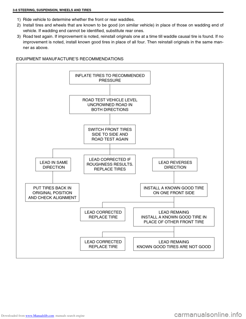
1) Ride vehicle to determine whether the front or rear waddles.
2) Install tires and wheels that are known to be good (on similar vehicle) in place of those on wadding end of
vehicle. If wadding end cannot be identified, substitute rear ones.
3) Road test again. If improvement is noted, reinstall originals one at a time till waddle causal tire is found. If no
improvement is noted, install known good tires in place of all four. Then reinstall originals in the same man-
ner as above.
EQUIPMENT MANUFACTURE’S RECOMMENDATIONS
INFLATE TIRES TO RECOMMENDED
PRESSURE
ROAD TEST VEHICLE LEVEL
UNCROWNED ROAD IN
BOTH DIRECTIONS
SWITCH FRONT TIRES
SIDE TO SIDE AND
ROAD TEST AGAIN
LEAD CORRECTED IF
ROUGHNESS RESULTS.
REPLACE TIRES
INSTALL A KNOWN GOOD TIRE
ON ONE FRONT SIDE
LEAD REMAING
INSTALL A KNOWN GOOD TIRE IN
PLACE OF OTHER FRONT TIRE
LEAD REMAING
KNOWN GOOD TIRES ARE NOT GOOD
LEAD CORRECTED
REPLACE TIRE
LEAD REVERSES
DIRECTION
PUT TIRES BACK IN
ORIGINAL POSITION
AND CHECK ALIGNMENT
LEAD IN SAME
DIRECTION
LEAD CORRECTED
REPLACE TIRE
Page 132 of 687
Downloaded from www.Manualslib.com manuals search engine POWER STEERING (P/S) SYSTEM (If equipped) 3B1-1
6F1
6F2
6G
6H
6K
3B1
7D
7E
7F
7E
7F
8A
8B
8C
8D
8E
9
10
10A
10B
SECTION 3B1
POWER STEERING (P/S) SYSTEM
(If equipped)
CONTENTS
General Description ......................................3B1-2
Diagnosis .......................................................3B1-3
Diagnosis Table .......................................... 3B1-3
Steering Wheel Play Check ........................ 3B1-5
Steering Force Check ................................. 3B1-5
Power Steering Belt Check ......................... 3B1-6
Power Steering Belt Tension Adjustment .... 3B1-6
Power Steering Fluid Level Check .............. 3B1-6
Idle-Up System Check ................................ 3B1-7
Power Steering Fluid Leakage Check ......... 3B1-7Air Bleeding Procedure ............................... 3B1-8
Hydraulic Pressure In P/S Circuit Check .. 3B1-10
On-Vehicle Service ..................................... 3B1-12
Power Steering Belt .................................. 3B1-12
Power Steering (P/S) Pump ...................... 3B1-12
Power Steering (P/S) Gear Box ................ 3B1-18
Tightening Torque Specifications ............. 3B1-21
Required Service Materials ........................ 3B1-21
Special Tools ............................................... 3B1-21 WARNING:
For vehicles equipped with Supplemental Restraint (Air Bag) System :
Service on and around the air bag system components or wiring must be performed only by an
authorized SUZUKI dealer. Refer to “Air Bag System Components and Wiring Location View” under
“General Description” in air bag system section in order to confirm whether you are performing ser-
vice on or near the air bag system components or wiring. Please observe all WARNINGS and “Ser-
vice Precautions” under “On-Vehicle Service” in air bag system section before performing service
on or around the air bag system components or wiring. Failure to follow WARNINGS could result in
unintentional activation of the system or could render the system inoperative. Either of these two
conditions may result in severe injury.
Technical service work must be started at least 90 seconds after the ignition switch is turned to the
“LOCK” position and negative cable is disconnected from the battery. Otherwise, the system may
be activated by reserve energy in the Sensing and Diagnostic Module (SDM).
NOTE:
All steering gear fasteners are important attaching parts in that they could affect the performance of
vital parts and systems, and/or could result in major repair expense. They must be replaced with one
of the same part number or with an equivalent part if replacement becomes necessary. Do not use a
replacement part of lesser quality or substitute design. Torque values must be used as specified dur-
ing reassembly to assure proper retention of these parts.
Page 134 of 687

Downloaded from www.Manualslib.com manuals search engine POWER STEERING (P/S) SYSTEM (If equipped) 3B1-3
Diagnosis
Diagnosis Table
Condition Possible Cause Correction
Steering wheel feels
heavy
(at low speed)Fluid deteriorated, low viscosity, different type of
fluid mixedChange fluid.
Pipes or hoses deformed, air entering through
jointCorrect or replace.
Insufficient air bleeding from piping Bleed air.
Belt worn, lacking in tension Adjust belt tension or replace belt
as necessary.
Tire inflation pressure too low Inflate tire.
Wheel alignment out of adjustment Adjust front wheel alignment.
Steering wheel installed improperly (twisted) Install steering wheel correctly.
Hydraulic pressure failing to rise (See NOTE
“A”.)Replace P/S pump.
Slow hydraulic pressure rise (See NOTE “A”.)
Steering wheel feels
heavy momentarily
when turning it to the
left or right.Air drawn in due to insufficient amount of fluid Add fluid and bleed air.
Slipping belt Adjust belt tension or replace belt
as necessary.
No idle-up (See NOTE
“B”.)Defective pressure switch Replace pressure switch
(terminal set).
NOTE:
“A” : Be sure to warm up engine fully before performing this check. Pump vanes are sometimes
hard to come out where temperature is low.
“B” : Acceptable if idling speed does not drop.
Condition Possible Cause Correction
Steering wheel returns
slowly from turns.
(See NOTE “C”.)Dust or foreign object mixed in fluid Change fluid.
Deformed pipes or hoses Correct or replace.
Steering column installed improperly Install correctly.
Wheel alignment maladjusted Adjust.
Linkage or joints not operating smoothly Correct.
Vehicle pulls to one
side during straight
driving.Low or uneven tire inflation pressure Inflate tire (s) as necessary.
Wheel alignment maladjusted Adjust.
Defective spool valve Replace gear box assembly.
Steering wheel play is
large and vehicle wan-
ders.Loose steering shaft nut Retighten.
Loose linkage or joint Retighten.
Loose gear box fixing bolt Retighten.
Front wheel bearing worn Replace.
Fluid leakage
Loose joints of hydraulic pressure pipes and
hosesRetighten.
Deformed or damaged pipes or hoses Correct or replace.
Gear box Replace gear box assembly.
Page 138 of 687

Downloaded from www.Manualslib.com manuals search engine POWER STEERING (P/S) SYSTEM (If equipped) 3B1-7
Idle-Up System Check
1) Warm up engine to normal operating temperature.
2) Turn A/C switch OFF, if equipped.
3) Turn steering wheel fully and check idle speed.
Engine idle speed drops a little momentarily when steering wheel is turned fully but returns to its specified
level immediately. If power steering pressure switch connector is connected, check the same with that con-
nector disconnected. Momentary drop of engine idle speed should be less when it is connected than when
disconnected.
Power Steering Fluid Leakage Check
Start engine and turn steering wheel fully to the right and left so that maximum hydraulic pressure is applied to
system. Then visually check gear box, P/S pump and P/S fluid reservoir respectively and each joint of hydraulic
pressure piping for leakage. During this check, however, never keep steering wheel turned fully for longer than
10 seconds.