2005 SUZUKI JIMNY Bleed
[x] Cancel search: BleedPage 150 of 687
Downloaded from www.Manualslib.com manuals search engine POWER STEERING (P/S) SYSTEM (If equipped) 3B1-19
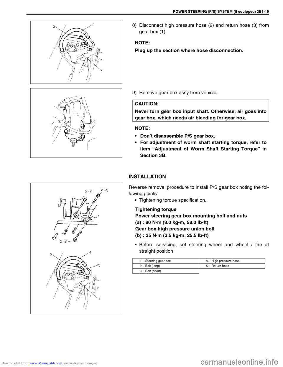
8) Disconnect high pressure hose (2) and return hose (3) from
gear box (1).
9) Remove gear box assy from vehicle.
INSTALLATION
Reverse removal procedure to install P/S gear box noting the fol-
lowing points.
Tightening torque specification.
Tightening torque
Power steering gear box mounting bolt and nuts
(a) : 80 N·m (8.0 kg-m, 58.0 lb-ft)
Gear box high pressure union bolt
(b) : 35 N·m (3.5 kg-m, 25.5 lb-ft)
Before servicing, set steering wheel and wheel / tire at
straight position. NOTE:
Plug up the section where hose disconnection.
CAUTION:
Never turn gear box input shaft. Otherwise, air goes into
gear box, which needs air bleeding for gear box.
NOTE:
Don’t disassemble P/S gear box.
For adjustment of worm shaft starting torque, refer to
item “Adjustment of Worm Shaft Starting Torque” in
Section 3B.
1. Steering gear box 4. High pressure hose
2. Bolt (long) 5. Return hose
3. Bolt (short)
Page 151 of 687

Downloaded from www.Manualslib.com manuals search engine 3B1-20 POWER STEERING (P/S) SYSTEM (If equipped)
Install pitman arm (1) to sector shaft (2) of P/S gear box (3)
with match marks “A” and “B” aligned as shown in figure and
torque to specification.
Tightening torque
Pitman arm mounting nut
(a) : 135 N·m (13.5 kg-m, 98.0 lb-ft)
Install lower shaft by the following steps.
1) Align flat part of steering gear box worm shaft (1) with bolt
hole in lower joint as shown. Then insert lower joint (2) onto
worm shaft.
2) Be sure that front wheels and steering wheel are in straight-
forward state and insert upper joint onto steering shaft.
3) Torque lower shaft joint bolt to specification.
Tightening torque
Steering shaft lower joint bolt
(a) : 25 N·m (2.5 kg-m, 18.0 lb-ft)
Fill engine coolant to radiator.
Bleed air in P/S circuit referring to “Air Bleeding Procedure”
in this section.
Page 152 of 687

Downloaded from www.Manualslib.com manuals search engine POWER STEERING (P/S) SYSTEM (If equipped) 3B1-21
Tightening Torque Specifications
Required Service Materials
Special Tools
Fastening partTightening torque
Nm kg-m lb-ft
Tension pulley bolt 25 2.5 18.0
Oil pump mounting bolt 25 2.5 18.5
Oil pump high pressure union bolt 60 6.0 43.5
Oil pump cover bolts 28 2.8 20.0
Pressure switch 28 2.8 20.0
Suction connector bolt 12 1.2 8.5
Power steering gear box mounting bolt
and nuts80 8.0 58.0
Gear box high pressure union bolt 35 3.5 25.5
Pitman arm mounting nut 135 13.5 98.0
Steering shaft joint bolt 25 2.5 18.5
Plug 60 6.0 43.5
MaterialRecommended SUZUKI product
(Part Number)Use
Power steering
fluidAn equivalent of DEXRON
®-II,
DEXRON
®-IIE or DEXRON®-III.To fill P/S fluid reservoir
Parts lubrication when installing
Lithium greaseSUPER GREASE (A)
(99000-25010)Oil seal lip of P/S pump pulley shaft
09915-77411 09915-77420 09944-18211 09945-35010
Oil pressure gauge Oil pressure gauge
attachment & hose setTorque check socket Air bleeding hose set
Page 232 of 687

Downloaded from www.Manualslib.com manuals search engine REAR SUSPENSION 3E-13
4) Remove wheel speed sensor (4) from rear axle housing (if
equipped with ABS).
5) Disconnect brake pipe(s) (2) from wheel cylinder and put
wheel cylinder bleeder plug cap (1) onto pipe to prevent fluid
from spilling.
6) Remove brake back plate nuts (3) from axle housing.
7) Using special tools indicated, draw out axle shaft with brake
back plate.
Special tool
(A) : 09942-15510
(B) : 09943-35511 or 09943-35512
8) If equipped with ABS, in order to remove sensor rotor from
retainer ring, grind with a grinder one part of the sensor rotor
as illustrated till it becomes thin.
9) Break with a chisel the thin ground sensor rotor, and it can
be removed (if equipped with ABS). CAUTION:
Do not pull wire harness or twist more than necessary
when removing rear wheel speed sensor (4).
Do not cause damage to surface of rear wheel speed
sensor (4) or pole piece and do not allow dust, etc. to
enter its installation hole.
Page 235 of 687
Downloaded from www.Manualslib.com manuals search engine 3E-16 REAR SUSPENSION
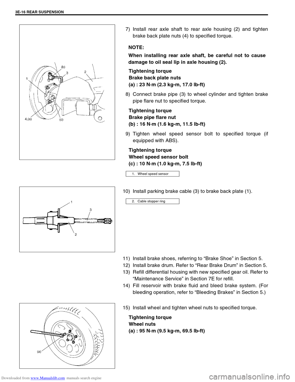
7) Install rear axle shaft to rear axle housing (2) and tighten
brake back plate nuts (4) to specified torque.
Tightening torque
Brake back plate nuts
(a) : 23 N·m (2.3 kg-m, 17.0 lb-ft)
8) Connect brake pipe (3) to wheel cylinder and tighten brake
pipe flare nut to specified torque.
Tightening torque
Brake pipe flare nut
(b) : 16 N·m (1.6 kg-m, 11.5 lb-ft)
9) Tighten wheel speed sensor bolt to specified torque (if
equipped with ABS).
Tightening torque
Wheel speed sensor bolt
(c) : 10 N·m (1.0 kg-m, 7.5 lb-ft)
10) Install parking brake cable (3) to brake back plate (1).
11) Install brake shoes, referring to “Brake Shoe” in Section 5.
12) Install brake drum. Refer to “Rear Brake Drum” in Section 5.
13) Refill differential housing with new specified gear oil. Refer to
“Maintenance Service” in Section 7E for refill.
14) Fill reservoir with brake fluid and bleed brake system. (For
bleeding operation, refer to “Bleeding Brakes” in Section 5.)
15) Install wheel and tighten wheel nuts to specified torque.
Tightening torque
Wheel nuts
(a) : 95 N·m (9.5 kg-m, 69.5 lb-ft) NOTE:
When installing rear axle shaft, be careful not to cause
damage to oil seal lip in axle housing (2).
1. Wheel speed sensor
2. Cable stopper ring
Page 249 of 687
Downloaded from www.Manualslib.com manuals search engine 3F-6 WHEELS AND TIRES
Maintenance and Minor Adjustments
Wheel and Tire
Wheel repairs that use welding, heating, or peening are not approved. All damaged wheels should be replaced.
Studs
If a broken stud is found, see Section 3E (rear) or Section 3D (front) for Note and Replacement procedure.
Matched tires and wheels
(For vehicle equipped with steel wheels)
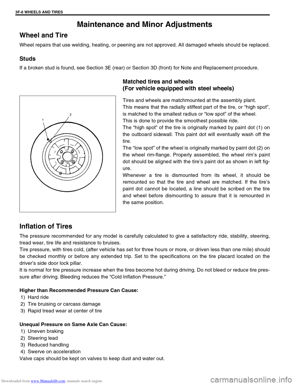
Tires and wheels are matchmounted at the assembly plant.
This means that the radially stiffest part of the tire, or “high spot”,
is matched to the smallest radius or “low spot” of the wheel.
This is done to provide the smoothest possible ride.
The “high spot” of the tire is originally marked by paint dot (1) on
the outboard sidewall. This paint dot will eventually wash off the
tire.
The “low spot” of the wheel is originally marked by paint dot (2) on
the wheel rim-flange. Properly assembled, the wheel rim’s paint
dot should be aligned with the tire’s paint dot as shown in left fig-
ure.
Whenever a tire is dismounted from its wheel, it should be
remounted so that the tire and wheel are matched. If the tire’s
paint dot cannot be located, a line should be scribed on the tire
and wheel before dismounting to assure that it is remounted in
the same position.
Inflation of Tires
The pressure recommended for any model is carefully calculated to give a satisfactory ride, stability, steering,
tread wear, tire life and resistance to bruises.
Tire pressure, with tires cold, (after vehicle has set for three hours or more, or driven less than one mile) should
be checked monthly or before any extended trip. Set to the specifications on the tire placard located on the
driver’s side door lock pillar.
It is normal for tire pressure increase when the tires become hot during driving. Do not bleed or reduce tire pres-
sure after driving. Bleeding reduces the “Cold Inflation Pressure.”
Higher than Recommended Pressure Can Cause:
1) Hard ride
2) Tire bruising or carcass damage
3) Rapid tread wear at center of tire
Unequal Pressure on Same Axle Can Cause:
1) Uneven braking
2) Steering lead
3) Reduced handling
4) Swerve on acceleration
Valve caps should be kept on valves to keep dust and water out.
Page 262 of 687
Downloaded from www.Manualslib.com manuals search engine BRAKES 5-1
6F1
6F2
6G
6H
6K
7A
7A1
7B1
7C1
7D
7E
5
9
10
10A
10B
9
10
10A
10B
SECTION 5
BRAKES
CONTENTS
General Description ......................................... 5-3
Diagnosis .......................................................... 5-4
Road Testing Brakes ...................................... 5-4
Brake Fluid Leaks .......................................... 5-4
Substandard or Contaminated Brake Fluid .... 5-4
Diagnosis Table ............................................. 5-5
Brake Pedal Free Height Adjustment ............. 5-8
Brake Pedal Play Check ................................ 5-8
Stop Light Switch Adjustment ........................ 5-8
Excessive Pedal Travel Check ....................... 5-9
Front Brake Disc Check ................................. 5-9
Front Brake Pad Check .................................. 5-9
Rear Brake Shoe Check .............................. 5-10
Master Cylinder and Brake Fluid Level
Check ........................................................... 5-10
Rear Drum Brake Shoe Adjustment ............. 5-11
Parking Brake Inspection and Adjustment ... 5-11
Booster Operation Check ............................. 5-12Fluid Pressure Test
(If Equipped with LSPV) ............................... 5-15
On-Vehicle Service ........................................ 5-17
Air Bleeding of Brake System ...................... 5-17
Brake Hose and Pipe Inspection.................. 5-18
Front Disc Brake .......................................... 5-19
Brake pad ................................................. 5-20
Caliper assembly...................................... 5-22
Brake Disc.................................................... 5-26
Rear Brake ................................................... 5-29
Brake drum............................................... 5-29
Brake shoe ............................................... 5-32
Wheel Cylinder............................................. 5-33
Brake back plate ...................................... 5-34
Master Cylinder .............................................. 5-36
Master Cylinder Reservoir ........................... 5-36
Master Cylinder Assembly ........................... 5-37 WARNING:
For lifting point of vehicle, refer to Section 0A.
WARNING:
For vehicles equipped with Supplement Restraint (Air Bag) System:
Service on and around the air bag system components or wiring must be performed only by an
authorized SUZUKI dealer. Refer to “Air Bag System Components and Wiring Location View” under
“General Description” in air bag system section in order to confirm whether you are performing ser-
vice on or near the air bag system components or wiring. Please observe all WARNINGS and “Ser-
vice Precautions” under “On-Vehicle Service” in air bag system section before performing service
on or around the air bag system components or wiring. Failure to follow WARNINGS could result in
unintentional activation of the system or could render the system inoperative. Either of these two
conditions may result in severe injury.
Technical service work must be started at least 90 seconds after the ignition switch is turned to the
“LOCK” position and the negative cable is disconnected from the battery. Otherwise, the system
may be activated by reserve energy in the Sensing and Diagnostic Module (SDM).
NOTE:
When inspecting and servicing vehicle equipped with ABS, be sure to refer to section 5E first.
All brake fasteners are important attaching parts in that they could affect the performance of vital
parts and systems, and/or could result in major repair expense. They must be replaced with one of
same part number or with an equivalent part if replacement becomes necessary. Do not use a
replacement part of lesser quality or substitute design. Torque values must be used as specified
during reassembly to assure proper retention of all parts. There is to be no welding as it may result
in extensive damage and weakening of the metal.
Page 264 of 687
Downloaded from www.Manualslib.com manuals search engine BRAKES 5-3
General Description
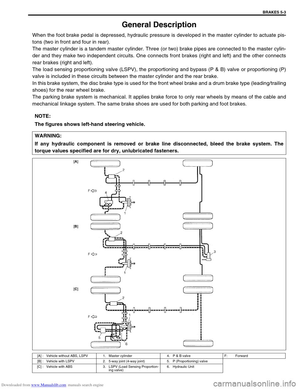
When the foot brake pedal is depressed, hydraulic pressure is developed in the master cylinder to actuate pis-
tons (two in front and four in rear).
The master cylinder is a tandem master cylinder. Three (or two) brake pipes are connected to the master cylin-
der and they make two independent circuits. One connects front brakes (right and left) and the other connects
rear brakes (right and left).
The load sensing proportioning valve (LSPV), the proportioning and bypass (P & B) valve or proportioning (P)
valve is included in these circuits between the master cylinder and the rear brake.
In this brake system, the disc brake type is used for the front wheel brake and a drum brake type (leading/trailing
shoes) for the rear wheel brake.
The parking brake system is mechanical. It applies brake force to only rear wheels by means of the cable and
mechanical linkage system. The same brake shoes are used for both parking and foot brakes.
NOTE:
The figures shows left-hand steering vehicle.
WARNING:
If any hydraulic component is removed or brake line disconnected, bleed the brake system. The
torque values specified are for dry, unlubricated fasteners.
[A] : Vehicle without ABS, LSPV 1. Master cylinder 4. P & B valve F: Forward
[B] : Vehicle with LSPV 2. 5-way joint (4-way joint) 5. P (Proportioning) valve
[C] : Vehicle with ABS 3. LSPV (Load Sensing Proportion-
ing valve)6. Hydraulic Unit