Page 614 of 687
Downloaded from www.Manualslib.com manuals search engine ENGINE AND EMISSION CONTROL SYSTEM 6E-9
ECM INPUT / OUTPUT CIRCUIT DIAGRAM
For TYPE A (See NOTE)
NOTE:
Type A is other than follows.
Type B is left hand steering vehicle equipped with fasten seat belt light and EGR valve or right hand
steering vehicle equipped with fasten seat belt light and immobilizer control system.
Page 616 of 687
Downloaded from www.Manualslib.com manuals search engine ENGINE AND EMISSION CONTROL SYSTEM 6E-11
For TYPE B (See NOTE)
NOTE:
See NOTE in “ECM INPUT / OUTPUT CIRCUIT DIAGRAM” for applicable model.
Page 618 of 687

Downloaded from www.Manualslib.com manuals search engine ENGINE AND EMISSION CONTROL SYSTEM 6E-13
ECM TERMINAL ARRANGEMENT TABLE
For TYPE A (See NOTE)
CONNEC-
TORTERMINAL WIRE COLOR CIRCUITCONNEC-
TORTERMINAL WIRE COLOR CIRCUIT
E191 B Ground for ECM
E187 W Backup power source
2 B/R Ground for drive circuit
8R/GImmobilizer indicator lamp
(if equipped)
3 B/R Ground for drive circuitDuty output terminal (vehicle without
immobilizer indicator lamp)
4 Bl/G Canister purge valve 9––
5 Bl/OrPower steering pressure switch
(if equipped)10 Bl Main relay
6 G/Y IAC valve 11 Br Tachometer
7 P/B Heater of HO2S-1 (if equipped) 12 Y/B Data link connector (5 V)
8 W/B No.4 fuel injector 13 WHeated oxygen sensor-2
(if equipped)
9 R/W No.1 fuel injector 14 W/BIDiagnosis switch terminal
(vehicle without immobilizer indicator
lamp)
10 B/Bl Ground for sensor circuit 15 PTest switch terminal
(vehicle without immobilizer indicator
lamp)
11 W CMP sensor 16 G/W A/C SW signal (if equipped)
12––17 R/Y Lighting switch
13R
R/BlHeated oxygen sensor-1
(if equipped)
CO adjusting resistor (w/o HO2S)18 P/B A/C condenser fan relay (if equipped)
14 G/B ECT sensor 19 W/G Fuel pump relay
15 Lg/B IAT sensor 20 B/Bl Ground for sensor
16 Lg TP sensor 21 B/RThrottle opening signal output for A/T
(A/T)
17 Gr/BIEGR valve (stepper motor coil 3, if
equipped)22 Y/RFuel level gauge (vehicle with immo-
bilizer indicator lamp)
18 GrEGR valve (stepper motor coil 1, if
equipped)23––
19 Br/BIG coil assembly for No.2 and 3 spark
plugs24 Bl/Y Heater blower switch
20 Br/WIG coil assembly for No.1 and 4 spark
plugs
21 R/G No.2 fuel injector
E171––
22 Lg/R Power supply for sensor 2 R R-range signal (A/T)
23 G/R CKP sensor 3––
24––4––
25 W Knock sensor 5 B/Or Overdrive cut signal (A/T)
26 G MAP sensor 6 G/Y D-range idle-up signal (A/T)
27 W/R A/C evaporator temp. sensor 7 G/W Stop lamp switch
28 Gr/BEGR valve (stepper motor coil 4, if
equipped)8––
29 Gr/REGR valve (stepper motor coil 2, if
equipped)9 B/W Ignition switch
30––10––
31 W/G No.3 fuel injector 11 Y Vehicle speed sensor
12 G ABS signal (if equipped)
E181 P A/C compressor clutch (if equipped) 13B/Y (M/T)
B/R (A/T)Engine start signal
2 V/Y Malfunction indicator lamp 14––
3 P/G Data link connector (12 V) 15––
4 R/BI Heater of HO2S-2 (if equipped) 16 R/W Rear defogger switch (if equipped)
5 Bl/B Power source 17 G/RA/T failure signal (A/T) (vehicle with
immobilizer indicator lamp)
6 Bl/B Power source
NOTE:
See NOTE in “ECM INPUT / OUTPUT CIRCUIT DIAGRAM” for applicable model.
Page 619 of 687

Downloaded from www.Manualslib.com manuals search engine 6E-14 ENGINE AND EMISSION CONTROL SYSTEM
For TYPE B (See NOTE)
CONNEC-
TORTERMINAL WIRE COLOR CIRCUITCONNEC-
TORTERMINAL WIRE COLOR CIRCUIT
E191 B Ground for ECM
E187 W Backup power source
2 B/R Ground for drive circuit
8R/GImmobilizer indicator lamp
(if equipped)
3 B/R Ground for drive circuitDuty output terminal (vehicle without
immobilizer indicator lamp)
4 Bl/G Canister purge valve 9––
5 Bl/OrPower steering pressure switch
(if equipped)10 Bl Main relay
6 G/Y IAC valve 11 B/W Ignition switch
7 P/B Heater of HO2S-1 (if equipped) 12 R/W Rear defogger switch
8 W/B No.4 fuel injector 13––
9 R/W No.1 fuel injector 14 W/BIDiagnosis switch terminal
(vehicle without immobilizer indicator
lamp)
10 B/Bl Ground for sensor circuit 15 PTest switch terminal
(vehicle without immobilizer indicator
lamp)
11 W CMP sensor 16 G/W A/C SW signal (if equipped)
12––17 R/Y Lighting switch
13R
R/BlHeated oxygen sensor-1
(if equipped)
CO adjusting resistor (w/o HO2S)18 P/B A/C condenser fan relay (if equipped)
14 G/B ECT sensor 19 W/G Fuel pump relay
15 Lg/B IAT sensor 20B/Y (M/T)
B/R (A/T)Engine start signal
16 Lg TP sensor 21 G/W Stop lamp switch
17 Gr/BIEGR valve (stepper motor coil 3, if
equipped)22 Y Vehicle speed sensor
18 GrEGR valve (stepper motor coil 1, if
equipped)23––
19 Br/BIG coil assembly for No.2 and 3 spark
plugs24––
20 Br/WIG coil assembly for No.1 and 4 spark
plugs
21 R/G No.2 fuel injector
E171 W/R A/C evaporator temp. sensor
22 Lg/R Power supply for sensor 2 R R-range signal (A/T)
23 G/R CKP sensor 3––
24––4––
25 W Knock sensor 5 B/Or Overdrive cut signal (A/T)
26 G MAP sensor 6 G/Y D-range idle-up signal (A/T)
27––7 Y/B Data link connector
28 Gr/BEGR valve (stepper motor coil 4, if
equipped)8––
29 Gr/REGR valve (stepper motor coil 2, if
equipped)9 V/Y Malfunction indicator lamp
30––10––
31 W/G No.3 fuel injector 11 P/G Data link connector (12 V)
12 G ABS signal (if equipped)
E181 P A/C compressor clutch (if equipped) 13 Bl/Y Heater blower switch
2––14 B/Bl Ground for sensor
3––15 B/R Throttle opening sensor
4 R/BI Heater of HO2S-2 (if equipped) 16 Br Tachometer
5 Bl/B Power source 17––
6 Bl/B Power source
NOTE:
See NOTE in “ECM INPUT / OUTPUT CIRCUIT DIAGRAM” for applicable model.
Page 632 of 687

Downloaded from www.Manualslib.com manuals search engine ENGINE AND EMISSION CONTROL SYSTEM 6E-27
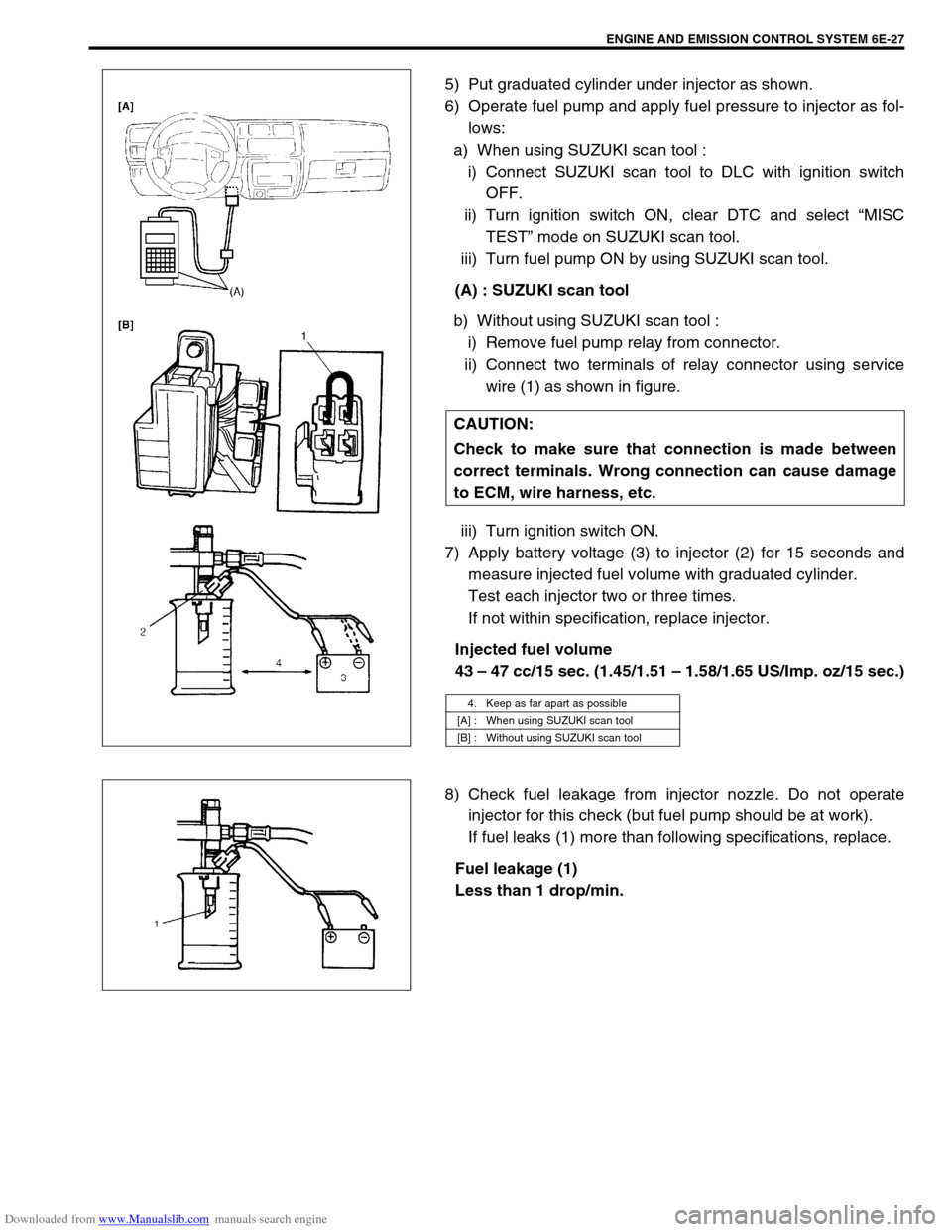
5) Put graduated cylinder under injector as shown.
6) Operate fuel pump and apply fuel pressure to injector as fol-
lows:
a) When using SUZUKI scan tool :
i) Connect SUZUKI scan tool to DLC with ignition switch
OFF.
ii) Turn ignition switch ON, clear DTC and select “MISC
TEST” mode on SUZUKI scan tool.
iii) Turn fuel pump ON by using SUZUKI scan tool.
(A) : SUZUKI scan tool
b) Without using SUZUKI scan tool :
i) Remove fuel pump relay from connector.
ii) Connect two terminals of relay connector using service
wire (1) as shown in figure.
iii) Turn ignition switch ON.
7) Apply battery voltage (3) to injector (2) for 15 seconds and
measure injected fuel volume with graduated cylinder.
Test each injector two or three times.
If not within specification, replace injector.
Injected fuel volume
43 – 47 cc/15 sec. (1.45/1.51 – 1.58/1.65 US/Imp. oz/15 sec.)
8) Check fuel leakage from injector nozzle. Do not operate
injector for this check (but fuel pump should be at work).
If fuel leaks (1) more than following specifications, replace.
Fuel leakage (1)
Less than 1 drop/min. CAUTION:
Check to make sure that connection is made between
correct terminals. Wrong connection can cause damage
to ECM, wire harness, etc.
4. Keep as far apart as possible
[A] : When using SUZUKI scan tool
[B] : Without using SUZUKI scan tool
Page 634 of 687
Downloaded from www.Manualslib.com manuals search engine ENGINE AND EMISSION CONTROL SYSTEM 6E-29
Electronic Control System
Engine control module (ECM)
REMOVAL
1) Disconnect battery negative cable at battery.
2) Disable air bag system, refer to “Disabling Air Bag System”
in Section 10B if equipped.
3) Remove glove box.
4) Disconnect ECM (1) and TCM (3) (if equipped) connectors.
5) Loosen 2 nuts (2) and remove ECM and TCM (if equipped).
INSTALLATION
1) Reverse removal procedure noting the following:
Connect connectors to ECM and TCM (if equipped)
securely.
Manifold absolute pressure sensor (MAP sensor)
INSPECTION
Check MAP sensor referring to “MAP Sensor Individual Check” in
DTC P0105 (No.11) Flow Table of Section 6. If malfunction is
found, replace.CAUTION:
As ECM consists of precision parts, be careful not to
expose it to excessive shock.
Page 643 of 687

Downloaded from www.Manualslib.com manuals search engine 6E-38 ENGINE AND EMISSION CONTROL SYSTEM
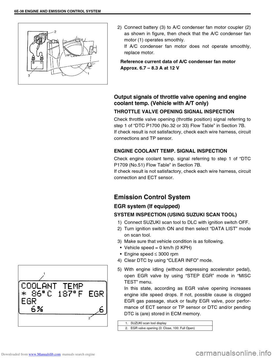
2) Connect battery (3) to A/C condenser fan motor coupler (2)
as shown in figure, then check that the A/C condenser fan
motor (1) operates smoothly.
If A/C condenser fan motor does not operate smoothly,
replace motor.
Reference current data of A/C condenser fan motor
Approx. 6.7 – 8.3 A at 12 V
Output signals of throttle valve opening and engine
coolant temp. (Vehicle with A/T only)
THROTTLE VALVE OPENING SIGNAL INSPECTION
Check throttle valve opening (throttle position) signal referring to
step 1 of “DTC P1700 (No.32 or 33) Flow Table” in Section 7B.
If check result is not satisfactory, check each wire harness, circuit
connections and TP sensor.
ENGINE COOLANT TEMP. SIGNAL INSPECTION
Check engine coolant temp. signal referring to step 1 of “DTC
P1709 (No.51) Flow Table” in Section 7B.
If check result is not satisfactory, check each wire harness, circuit
connection and ECT sensor.
Emission Control System
EGR system (If equipped)
SYSTEM INSPECTION (USING SUZUKI SCAN TOOL)
1) Connect SUZUKI scan tool to DLC with ignition switch OFF.
2) Turn ignition switch ON and then select “DATA LIST” mode
on scan tool.
3) Make sure that vehicle condition is as following.
Vehicle speed = 0 km/h (0 KPH)
Engine speed ≤ 3000 rpm
4) Clear DTC by using “CLEAR INFO” mode.
5) With engine idling (without depressing accelerator pedal),
open EGR valve by using “STEP EGR” mode in “MISC
TEST” menu.
In this state, according as EGR valve opening increases
engine idle speed drops. If not, possible cause is clogged
EGR gas passage, stuck or faulty EGR valve, poor perfor-
mance of ECT sensor or TP sensor or DTC and/or pending
DTC is (are) stored in ECM memory.
1. SUZUKI scan tool display
2. EGR valve opening (0: Close, 100: Full Open)
Page 645 of 687

Downloaded from www.Manualslib.com manuals search engine 6E-40 ENGINE AND EMISSION CONTROL SYSTEM
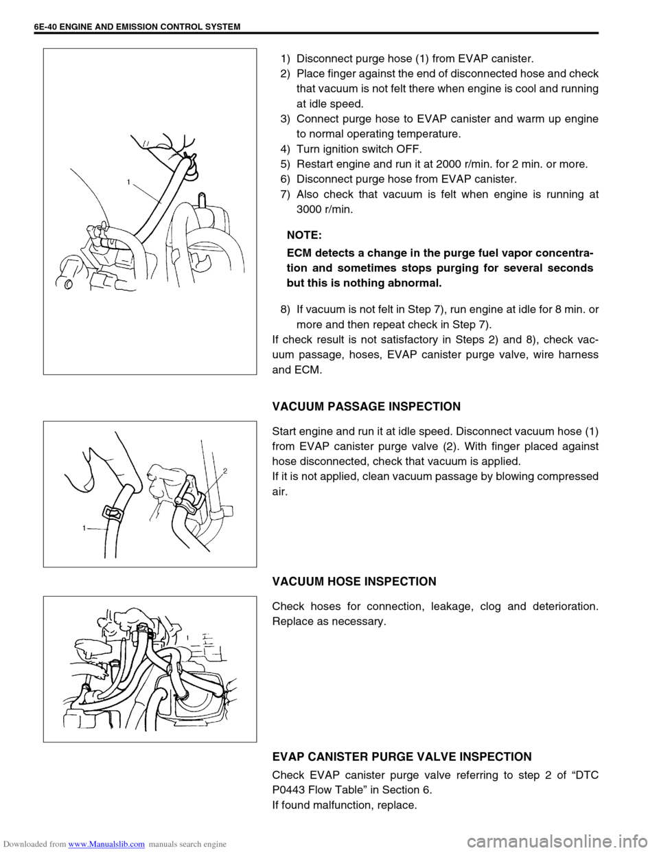
1) Disconnect purge hose (1) from EVAP canister.
2) Place finger against the end of disconnected hose and check
that vacuum is not felt there when engine is cool and running
at idle speed.
3) Connect purge hose to EVAP canister and warm up engine
to normal operating temperature.
4) Turn ignition switch OFF.
5) Restart engine and run it at 2000 r/min. for 2 min. or more.
6) Disconnect purge hose from EVAP canister.
7) Also check that vacuum is felt when engine is running at
3000 r/min.
8) If vacuum is not felt in Step 7), run engine at idle for 8 min. or
more and then repeat check in Step 7).
If check result is not satisfactory in Steps 2) and 8), check vac-
uum passage, hoses, EVAP canister purge valve, wire harness
and ECM.
VACUUM PASSAGE INSPECTION
Start engine and run it at idle speed. Disconnect vacuum hose (1)
from EVAP canister purge valve (2). With finger placed against
hose disconnected, check that vacuum is applied.
If it is not applied, clean vacuum passage by blowing compressed
air.
VACUUM HOSE INSPECTION
Check hoses for connection, leakage, clog and deterioration.
Replace as necessary.
EVAP CANISTER PURGE VALVE INSPECTION
Check EVAP canister purge valve referring to step 2 of “DTC
P0443 Flow Table” in Section 6.
If found malfunction, replace.NOTE:
ECM detects a change in the purge fuel vapor concentra-
tion and sometimes stops purging for several seconds
but this is nothing abnormal.