2005 SUZUKI JIMNY Lines
[x] Cancel search: LinesPage 14 of 687

Downloaded from www.Manualslib.com manuals search engine GENERAL INFORMATION 0A-9
When disconnecting vacuum hoses, attach a tag
describing the correct installation positions so that the
hoses can be reinstalled correctly.
After servicing fuel, oil, coolant, vacuum, exhaust or
brake systems, check all lines related to the system for
leaks.
For vehicles equipped with fuel injection systems, never
disconnect the fuel line between the fuel pump and
injector without first releasing the fuel pressure, or fuel
can be sprayed out under pressure.
When performing a work that produces a heat exceeding
80°C (176°F) in the vicinity of the electrical parts, remove
the heat sensitive electrical part(s) beforehand.
Use care not to expose connectors and electrical parts
to water which will be a cause of a trouble.
Always be careful not to handle electrical parts (com-
puter, relay, etc.) in a rough manner or drop them.
Page 32 of 687

Downloaded from www.Manualslib.com manuals search engine MAINTENANCE AND LUBRICATION 0B-1
0A 6F1
0B
0B
6G
1A 6H
1B 6K
37A
3A 7A1
3B1 7B1
3C1 7C1
3D 7D
3E 7E
3F 7F
4A2 8A
4B 8B
8C
58D
5A 8E
5B
5C 9
5E
5E1 10
10A
610B
6-1
6A1
6A2
6A4
6B
6C
6E1
6E2
SECTION 0B
MAINTENANCE AND LUBRICATION
CONTENTS
Maintenance Schedule .................................. 0B-2
Maintenance Schedule Under Normal
Driving Conditions ........................................ 0B-2
Maintenance Recommended Under Severe
Driving Conditions ........................................ 0B-4
Maintenance Service...................................... 0B-5
Engine .......................................................... 0B-5
Drive Belt .................................................. 0B-5
Valve Lash................................................ 0B-6
Engine Oil and Filter ................................. 0B-6
Engine Coolant ......................................... 0B-8
Exhaust System ....................................... 0B-8
Ignition System ............................................. 0B-9
Spark Plugs .............................................. 0B-9
Fuel System ................................................. 0B-9
Air Cleaner Filter ...................................... 0B-9
Fuel Lines and Connections ................... 0B-10
Fuel Filter ............................................... 0B-10
Fuel Tank ............................................... 0B-10
Emission Control System ........................... 0B-10
Crankcase Ventilation Hoses and
Connections ........................................... 0B-10
PCV (Positive Crankcase Ventilation)
Valve ..................................................... 0B-11Fuel Evaporative Emission Control
System ................................................... 0B-11
Chassis and Body ...................................... 0B-11
Clutch ..................................................... 0B-11
Brake Discs and Pads ............................ 0B-11
Brake Drums and Shoes ........................ 0B-12
Brake Hoses and Pipes.......................... 0B-12
Brake Fluid ............................................. 0B-12
Parking Brake Lever and Cable ............. 0B-13
Tires/Wheels .......................................... 0B-13
Suspension System ............................... 0B-14
Propeller Shafts...................................... 0B-15
Manual Transmission Oil........................ 0B-16
Automatic Transmission Fluid ................ 0B-16
Transfer and Differential Oil ................... 0B-17
Steering System ..................................... 0B-18
Steering Knuckle Seal ............................ 0B-18
Power Steering (P/S) System
(if equipped) ........................................... 0B-19
All Hinges, Latches and Locks ............... 0B-19
Final Inspection............................................ 0B-20
Recommended Fluids and Lubricants ....... 0B-22
WARNING:
For vehicles equipped with Supplemental Restraint (Air Bag) System:
Service on and around the air bag system components or wiring must be performed only by an
authorized SUZUKI dealer. Refer to “Air Bag System Components and Wiring Location View” under
“General Description” in air bag system section in order to confirm whether you are performing ser-
vice on or near the air bag system components or wiring. Please observe all WARNINGS and “Ser-
vice Precautions” under “On-Vehicle Service” in air bag system section before performing service
on or around the air bag system components or wiring. Failure to follow WARNINGS could result in
unintentional activation of the system or could render the system inoperative. Either of these two
conditions may result in severe injury.
Technical service work must be started at least 90 seconds after the ignition switch is turned to the
“LOCK” position and the negative cable is disconnected from the battery. Otherwise, the system
may be activated by reserve energy in the Sensing and Diagnostic Module (SDM).
Page 33 of 687

Downloaded from www.Manualslib.com manuals search engine 0B-2 MAINTENANCE AND LUBRICATION
Maintenance Schedule
Maintenance Schedule Under Normal Driving Conditions
NOTE:
This interval should be judged by odometer reading or months, whichever comes first.
This table includes service as scheduled up to 90,000 km (54,000 miles) mileage. Beyond 90,000 km
(54,000 miles), carry out the same services at the same intervals respectively.
IntervalKm (x 1,000) 15 30 45 60 75 90
Miles (x 1,000) 9 1827364554
Months 12 24 36 48 60 72
ENGINE
Drive belt V-belt I R I R I R
V-rib belt (Flat type)––I––R
Valve lash (clearance) –I–I–I
Engine oil and oil filter R R R R R R
Engine coolant––R––R
Exhaust system–I–I–I
IGNITION SYSTEM
✱Spark plugs When
unleaded
fuel is usedVehicle without
HO2SNickel spark
plug–R–R–R
Iridium spark
plug––R––R
Vehicle with
HO2SNickel spark
plug––R––R
Iridium spark
plug–––R––
When leaded fuel is used, refer to “Maintenance Recommended Under Severe Driving Condi-
tions” in this section.
FUEL SYSTEM
Air cleaner filter I I R I I R
Fuel lines and connections–I–I–I
Fuel filter Replace every 210,000 km (126,000 miles).
Fuel tank––I––I
EMISSION CONTROL SYSTEM
Crankcase ventilation hoses and connections
(Vehicle without HO2S)––I––I
✱PCV valve Vehicle without HO2S––I––I
Vehicle with HO2S–––––I
✱Fuel evaporative emission
control systemVehicle without HO2S–I–I–I
Vehicle with HO2S–––––I
NOTE:
“R”: Replace or change
“I”: Inspect and correct, replace or lubricate if necessary
For Sweden, items with
✱
✱✱ ✱ (asterisk) should be performed by odometer reading only.
For spark plugs, replace every 50,000 km if the local law requires.
Nickel spark plug: BKR6E-11 (NGK) or K20PR-U11 (DENSO)
Iridium spark plug: IFR5E11 (NGK) or SK16PR-A11 (DENSO)
Page 41 of 687

Downloaded from www.Manualslib.com manuals search engine 0B-10 MAINTENANCE AND LUBRICATION
REPLACEMENT
Replace air cleaner filter with new one according to steps 1), 2)
and 5), 6) of inspection procedure.
Fuel Lines and Connections
INSPECTION
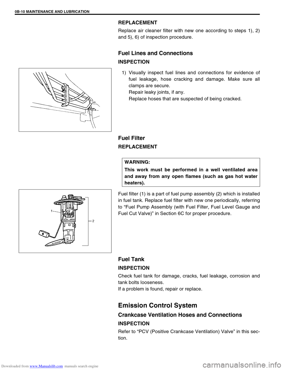
1) Visually inspect fuel lines and connections for evidence of
fuel leakage, hose cracking and damage. Make sure all
clamps are secure.
Repair leaky joints, if any.
Replace hoses that are suspected of being cracked.
Fuel Filter
REPLACEMENT
Fuel filter (1) is a part of fuel pump assembly (2) which is installed
in fuel tank. Replace fuel filter with new one periodically, referring
to “Fuel Pump Assembly (with Fuel Filter, Fuel Level Gauge and
Fuel Cut Valve)” in Section 6C for proper procedure.
Fuel Tank
INSPECTION
Check fuel tank for damage, cracks, fuel leakage, corrosion and
tank bolts looseness.
If a problem is found, repair or replace.
Emission Control System
Crankcase Ventilation Hoses and Connections
INSPECTION
Refer to “PCV (Positive Crankcase Ventilation) Valve” in this sec-
tion.
WARNING:
This work must be performed in a well ventilated area
and away from any open flames (such as gas hot water
heaters).
Page 46 of 687

Downloaded from www.Manualslib.com manuals search engine MAINTENANCE AND LUBRICATION 0B-15
REAR
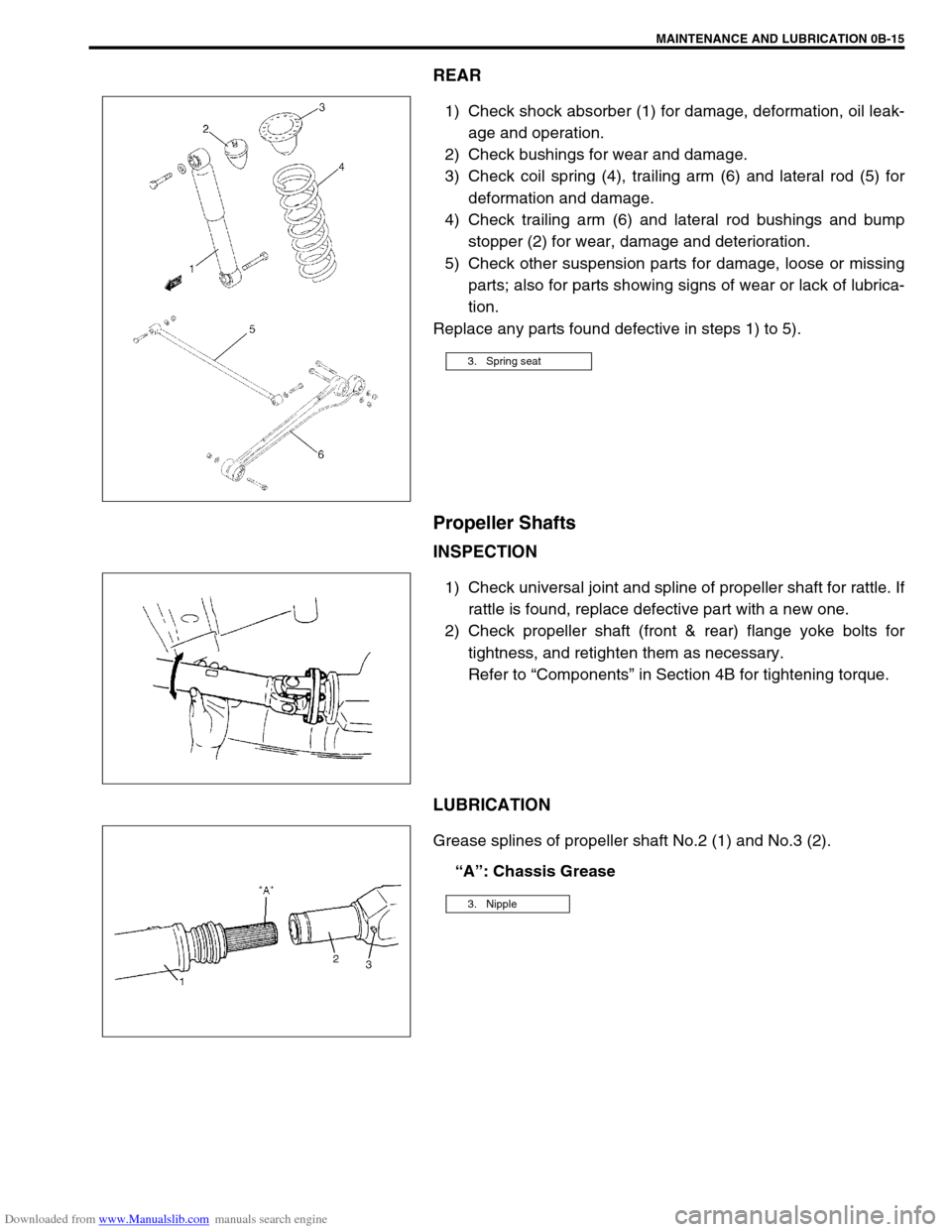
1) Check shock absorber (1) for damage, deformation, oil leak-
age and operation.
2) Check bushings for wear and damage.
3) Check coil spring (4), trailing arm (6) and lateral rod (5) for
deformation and damage.
4) Check trailing arm (6) and lateral rod bushings and bump
stopper (2) for wear, damage and deterioration.
5) Check other suspension parts for damage, loose or missing
parts; also for parts showing signs of wear or lack of lubrica-
tion.
Replace any parts found defective in steps 1) to 5).
Propeller Shafts
INSPECTION
1) Check universal joint and spline of propeller shaft for rattle. If
rattle is found, replace defective part with a new one.
2) Check propeller shaft (front & rear) flange yoke bolts for
tightness, and retighten them as necessary.
Refer to “Components” in Section 4B for tightening torque.
LUBRICATION
Grease splines of propeller shaft No.2 (1) and No.3 (2).
“A”: Chassis Grease
3. Spring seat
3. Nipple
Page 51 of 687

Downloaded from www.Manualslib.com manuals search engine 0B-20 MAINTENANCE AND LUBRICATION
Final Inspection
SEATS
Check that seat slides smoothly and locks securely at any position. Also check that reclining mechanism of front
seat back allows it to be locked at any angle.
SEAT BELT
Inspect belt system including webbing, buckles, latch plates, retractors and anchors for damage or wear.
If “REPLACE BELT” label on front seat belt is visible, replace belt. Check that seat belt is securely locked.
BATTERY ELECTROLYTE LEVEL CHECK
Check that the electrolyte level of all battery cells is between the upper and lower level lines on the case. If bat-
tery is equipped with built-in indicator, check battery condition by the indicator.
ACCELERATOR PEDAL OPERATION
Check that pedal operates smoothly without getting caught or interfered by any other part.
ENGINE START
Check engine start for readiness.
On automatic transmission vehicles, try to start the engine in each select lever position. The starting motor
should crank only in “P” (Park) or “N” (Neutral).
On manual transmission vehicles, place the shift lever in “Neutral,” depress clutch pedal fully any try to start.
EXHAUST SYSTEM CHECK
Check for leakage, cracks or loose supports.
CLUTCH (FOR MANUAL TRANSMISSION)
Check for the following.
Clutch is completely released when depressing clutch pedal,
No slipping clutch occurs when releasing pedal and accelerating.
Clutch itself is free from any abnormal condition. WARNING:
When carrying out road tests, select a safe place where no man or no running vehicle is seen so as to
prevent any accident.
WARNING:
Before performing the following check, be sure to have enough room around the vehicle. Then, firmly
apply both the parking brake and the regular brakes. Do not use the accelerator pedal. If the engine
starts, be ready to turn off the ignition promptly. Take these precautions because the vehicle could
move without warning and possibly cause personal injury or property damage.
Page 89 of 687

Downloaded from www.Manualslib.com manuals search engine 1B-28 AIR CONDITIONING (OPTIONAL)
Removing Manifold Gauge Set
When A/C system has been charged with a specified amount of
refrigerant, remove manifold gauge set as follows:
1) Close low pressure side valve of manifold gauge set. (The
high pressure side valve is closed continuously during the
process of charging.)
2) Close refrigerant container valve.
3) Stop engine.
4) Using shop rag, remove charging hoses from service valves.
This operation must be performed rapidly.
5) Put caps on service valves.
Leak Test
Whenever a refrigerant leak is suspected in the system or any
service operation has been performed which may result in dis-
turbing lines or connections, it is advisable to test for leaks.
Common sense should be used in performing any refrigerant leak
test, since the need and extent of any such test will, in general,
depend upon the nature of a complaint and the type of a service
performed on the system.
LIQUID LEAK DETECTOR
There are a number of fittings and places throughout the air con-
ditioning system where a liquid leak detector solution may be
used to pinpoint refrigerant leaks.
By merely applying the solution to the area in question with a
swab, such as attached to the cap of a vial, bubbles will form
within seconds if there is a leak.
For confined areas, such as sections of the evaporator and con-
denser, an electronic (refrigerant) leak detector (1) is more practi-
cal for determining leaks.WARNING:
High pressure side is naturally under high pressure. So,
care must be used to protect your eyes and skin.
Page 230 of 687

Downloaded from www.Manualslib.com manuals search engine REAR SUSPENSION 3E-11
7) Remove bushings (1) by using hydraulic press and special
tools.
Special tool
(A) : 09924-74510
(B) : 09951-16030
(C) : 09951-26010
INSTALLATION
1) Install bushings (1) by using hydraulic press and special
tools, noting the following points.
Special tool
(A) : 09913-85210
(B) : 09951-26010
For axle side bushings (1), install them so that center line
and slit lines of them are parallel as shown figure.
2. Slit
3. Center line of bushings
4. Slit line of bushings