2005 SUBARU LEGACY sensor
[x] Cancel search: sensorPage 230 of 627

3-59
Instruments and controls
– CONTINUED –
Mirrors
Always check that the inside and outside mirrors are
properly adjusted before you start driving. !Inside mirror
The inside mirror has a day and night position. Pull the
tab at the bottom of the mirror toward you for the night
position. Push it away for the day position. The night
position reduces glare from headlights. !
Auto-dimming mirror/compass (if
equipped)
A) Left button
B) Auto dimming indicator
C) Photosensor
D) Right button
The auto-dimming mirror/compass has an anti-glare
feature which automatically reduces glare coming
from headlights of vehicles behind you. It also con-
tains a built-in compass. " By pressing and releasing the left button, the auto-
matic dimming function is toggled on or off. When the
automatic dimming function is on, the auto dimming in-
UB3517BA
A
BC D
HS3037BC
Page 231 of 627

3-60
Instruments and controls
dicator light (green) located to the right of the button
will illuminate."
By pressing and releasing the right button, the com-
pass display is toggled on or off. When the compass is
on, an illuminated compass reading will appear in the
lower part of the mirror.
Even with the mirror in anti-glare mode, the mirror sur-
face turns bright if the transmission is shifted into re-
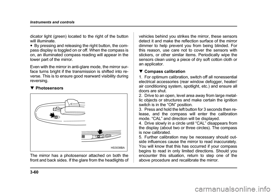
verse. This is to ensure good rearward visibility during reversing. ! Photosensors
The mirror has a photosensor attached on both the
front and back sides. If the glare from the headlights of vehicles behind you strikes the mirror, these sensors
detect it and make the reflection surface of the mirror
dimmer to help prevent you from being blinded. For
this reason, use care not to cover the sensors with
stickers, or other similar items. Periodically wipe the
sensors clean using a piece of dry soft cotton cloth or
an applicator. !
Compass calibration
1. For optimum calibration, switch off all nonessential
electrical accessories (rear window defogger, heater/
air conditioning system, spotlight, etc.) and ensure all
doors are shut.
2. Drive to an open, level area away from large metal-
lic objects or structures and make certain the ignition
switch is in the “ON” position.
3. Press and hold the left button for 3 seconds then re-
lease, and the compass will enter the calibration
mode. “CAL” and direction will be displayed.
4. Drive slowly in a circle until “CAL” disappears from
the display (about two or three circles). The compass
is now calibrated.
5. Further calibration may be necessary should out-
side influences cause the mirror to read inaccurately.
You will know that this has occurred if your compass
begins to read in only limited directions. Should you
encounter this situation, return to step one of the
above procedure and recalibrate the mirror.
HS3038BA
Page 236 of 627

4-1
4
Climate control
Ventilator ....................................................... 4-2 Air flow selection .............................................. 4-2
Center and side ventilators .............................. 4-3
Manual climate control system (if equipped) ............................................... 4-4Control panel ..................................................... 4-4
Heater operation ............................................... 4-7
Air conditioner operation ................................. 4-9
Automatic climate control system (if equipped) ............................................... 4-10Temperature sensors ....................................... 4-16
Operating tips for heater and air conditioner ........................................... 4-17Cleaning ventilator grille .................................. 4-17
Efficient cooling after parking in direct sunlight ........................................................... 4-18
Lubrication oil circulation in the refrigerant
circuit .............................................................. 4-18
Checking air conditioning system before summer season .................................. 4-18
Cooling and dehumidifying in high humidity and low temperature weather condition ...... 4-18
Air conditioner compressor shut-off
when engine is heavily loaded ...................... 4-18
Refrigerant for your climate control system .. 4-18
Air filtration system (if equipped) ................ 4-19
Page 251 of 627

4-16
Climate control
ed, a “ ” indicator light appears on the display.
(Outside air): Outside air is drawn into the pas-
senger compartment. When the climate control sys-
tem is operated in the “AUTO” mode, this position is
selected automatically. (There is one exception: When
the temperature control dial is turned fully counter-
clockwise, the recirculation mode is automatically se-
lected.) When the outside air mode is selected, a
“ ” indicator light appears on the display.
Continued operation in the “ ” position
may fog up the windows. Switch to the
“ ” position as soon as the outside dusty
condition clears.
NOTE
When driving on a dusty road or behind a vehicle
that emits unpleasant exhaust gases, set the air
inlet selection button to the “ ” position.
From time to time, return the air inlet selection but-
ton to the “ ” position to draw outside air
into the passenger compartment. !
Temperature sensors
A) Solar sensor
B) Interior air temperature sensor
The automatic climate control system employs several
sensors. These sensors are delicate. If they are treat-
ed incorrectly and become damaged, the system may
not be able to control the interior temperature correct-
ly. To avoid damaging the sensors, observe the follow-
ing precautions:
– Do not subject the sensors to impact.
– Keep water away from the sensors.
– Do not cover the sensors.
A
B
UB4210BB
Page 252 of 627

4-17
Climate control
– CONTINUED –
The sensors are located as follows:
– Solar sensor: beside windshield defroster grille
– Interior air temperature sensor: on the side of the
driver-side part of the center panel
– Outside temperature sensor: behind front grille. Operating tips for heater and air con-
ditioner !
Cleaning ventilator grille
Always keep the front ventilator inlet grille free of
snow, leaves, or other obstructions to ensure efficient
heating and defrosting. Since the condenser is located
in front of the radiator, this area should be kept clean
because cooling performance is impaired by any ac-
cumulation of insects and leaves on the condenser.
UB4203BA
Page 404 of 627

7-49
Starting and operating
– CONTINUED –
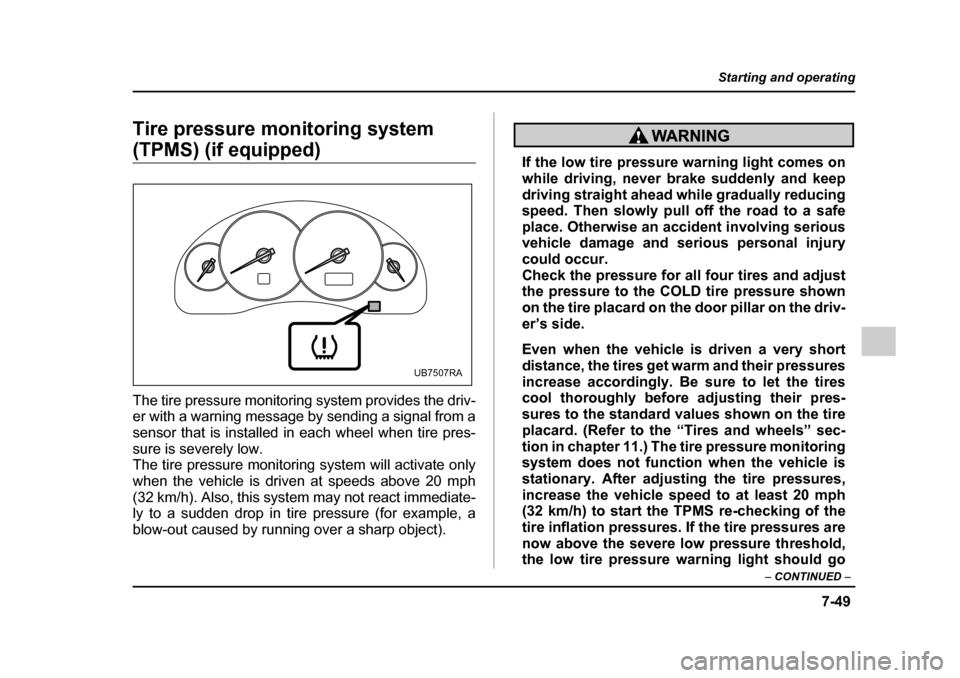
Tire pressure monitoring system
(TPMS) (if equipped)
The tire pressure monitoring system provides the driv-
er with a warning message by sending a signal from a
sensor that is installed in each wheel when tire pres-
sure is severely low.
The tire pressure monitoring system will activate only
when the vehicle is driven at speeds above 20 mph
(32 km/h). Also, this system may not react immediate-
ly to a sudden drop in tire pressure (for example, a
blow-out caused by running over a sharp object).If the low tire pressure warning light comes on
while driving, never brake suddenly and keep
driving straight ahead while gradually reducing
speed. Then slowly pull off the road to a safe
place. Otherwise an accident involving serious
vehicle damage and serious personal injury
could occur.
Check the pressure for all four tires and adjust
the pressure to the COLD tire pressure shown
on the tire placard on the door pillar on the driv-
er’s side.
Even when the vehicle is driven a very short
distance, the tires get warm and their pressures
increase accordingly. Be sure to let the tires
cool thoroughly before adjusting their pres-
sures to the standard values shown on the tire
placard. (Refer to the “Tires and wheels” sec-
tion in chapter 11.) The tire pressure monitoring
system does not function when the vehicle is
stationary. After adjusting the tire pressures,
increase the vehicle speed to at least 20 mph
(32 km/h) to start the TPMS re-checking of the
tire inflation pressures. If the tire pressures are
now above the severe low pressure threshold,
the low tire pressure warning light should go
UB7507RA
Page 405 of 627

7-50
Starting and operating
off a few minutes later.
If this light still comes on while driving after ad-
justing the tire pressure, a tire may have signif-
icant damage and a fast leak that causes the
tire to lose air rapidly. If you have a flat tire, re-
place it with a spare tire as soon as possible.
When a spare tire is mounted or a wheel rim is
replaced without the original pressure sensor/
transmitter being transferred, the low tire pres-
sure warning light will flash. This indicates the
TPMS is unable to monitor all four road wheels.
Contact your SUBARU dealer as soon as possi-
ble for tire and sensor replacement and/or sys- tem resetting.
Do not inject any tire liquid or aerosol tire seal- ant into the tires, as this may cause a malfunc-
tion of the tire pressure sensors. If the light
flashes, promptly contact a SUBARU dealer to
have the system inspected.
Do not place metal film or any metal parts under
the driver’s seat. This may cause poor recep-
tion of the signals from the tire pressure sen-
sors, which are located there, and the tire pres-
sure monitoring system will not function prop-
erly.
NOTE
This device complies with Part 15 of the FCC
Rules and with RSS-210 of Industry Canada. Oper-ation is subject to the following two conditions: (1)
This device may not cause harmful interference,
and (2) this device must accept any interference
received, including interference that may cause
undesired operation.
Changes or modifications not expressly approved
by the party responsible for compliance could
void the user’s authority to operate the equipment.
Page 458 of 627

9-3
In case of emergency
– CONTINUED –
Temporary spare tire
"Never tow a trailer when the temporary spare
tire is used. The temporary spare tire is not de-
signed to sustain the towing load. Use of the
temporary spare tire when towing can result in
failure of the spare tire and/or less stability of
the vehicle and may lead to an accident. " When a spare tire is mounted or a wheel rim
is replaced without the original pressure sen-
sor/transmitter being transferred, the low tire
pressure warning light will flash. This indicates
the tire pressure monitoring system (TPMS) is
unable to monitor all four road wheels. Contact
your SUBARU dealer as soon as possible for
tire and sensor replacement and/or system re-
setting.
Never use any temporary spare tire other than
the original. Using other sizes may result in se-
vere mechanical damage to the drive train of
your vehicle.
The temporary spare tire is smaller and lighter than a
conventional tire and is designed for emergency use
only. Remove the temporary spare tire and re-install
the conventional tire as soon as possible because the
spare tire is designed only for temporary use.
Check the inflation pressure of the temporary spare
tire periodically to keep the tire ready for use. The cor-
rect pressure is 60 psi (420 kPa, 4.2 kgf/cm 2
).
When using the temporary spare tire, note the follow-
ing: " Do not exceed 50 mph (80 km/h).
" Do not put a tire chain on the temporary spare tire.
Because of the smaller tire size, a tire chain will not fit
properly. " Do not use two or more temporary spare tires at the
same time. " Do not drive over obstacles. This tire has a smaller
diameter, so road clearance is reduced.