Page 201 of 502
0-4
RODIUS 2005.07
3170-01
MANUAL TRANSMISSION
1. MANUAL TRANSMISSION OVERVIEW
4WD
2WD
TSM54/52 transmission is designed to link the gear ratio, installation dimensions and shapes
with current T5 transmission and BTRA automatic transmission. It provides maximum
drivability by the optimized engine torque and gear ratio.
TSM54/52 transmission uses linkage type shift elements directly connected to the
transmission. It prevent the transmission from shifting to the reverse gear from 5th gea
r
when shifting to reverse gear. It also prevents the break and wear. 1.
2.
Page 202 of 502
0-5
MANUAL TRANSMISSION
RODIUS 2005.07
3170-01
1) Features
All gears use the helical type and high
strength materials. 3.
The helical type gear provides less noise.
The synchronizing devices are installed in
1/2, 3/4, 5/R gears. To prevent the double
engagement, the independent interlock
devices are installed. 4.
TSM54/52 transmission uses the inertia
lock type key to make smooth gea
r
engagement and to provide silent gea
r
engagement.
The clutch release system is available to
use CSC (Concentric Slave Cylinder) o
r
Fork type according to the vehicle model.
New Rexton uses the fork type
clutch release system.
The semi-remote control type gear shift
mechanism is used to prevent incorrect
shifting. 5.
6.
Page 203 of 502
0-6
RODIUS 2005.07
3170-01
MANUAL TRANSMISSION
2. CIRCUIT DIAGRAM (BACKUP LAMP)
Page 205 of 502

0-4
RODIUS 2005.07
3010-01
CLUTCH
1. OVERVIEW
1) Driving Elements
The driving elements consist of two flat surfaces machined to a smooth finish.
One of these is the rear face of the engine flywheel and the other is the clutch cover pressure
plate. The clutch pressure plate is fitted into a clutch steel cover, which is bolted to the flywheel.
2) Driven Elements
The driven element is the clutch disc with a splined hub which is free to slide lengthwise along
the splines of the input shaft. The driving and driven elements are held in contact by spring
pressure. This pressure is exerted by a diaphragm spring in the clutch cover pressure plate
assembly.
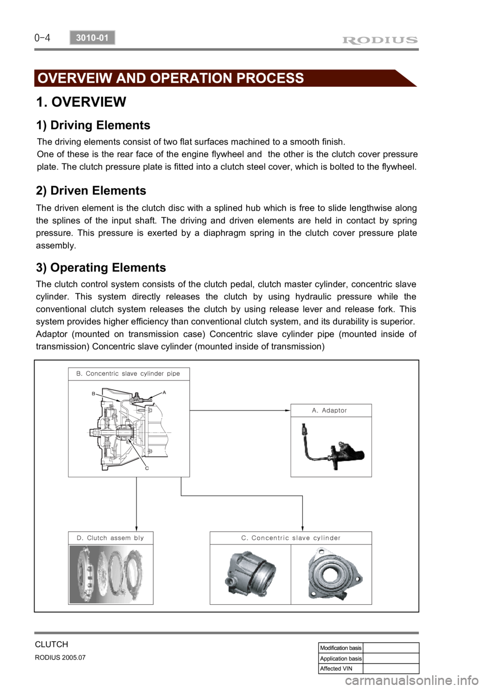
3) Operating Elements
The clutch control system consists of the clutch pedal, clutch master cylinder, concentric slave
cylinder. This system directly releases the clutch by using hydraulic pressure while the
conventional clutch system releases the clutch by using release lever and release fork. This
system provides higher efficiency than conventional clutch system, and its durability is superior.
Adaptor (mounted on transmission case) Concentric slave cylinder pipe (mounted inside o
f
transmission) Concentric slave cylinder (mounted inside of transmission)
Page 214 of 502

0-7
TORQUE ON DEMAND
RODIUS 2005.07
3240-01
2) Transfer Case
(1) Planetary gear set
Planetary Gear set consists of sun gear, ring gear and carrier. It is engaged with the gear in
“HIGH-LOW” collar to increase the driving force by reducing vehicle speed.
Sun gear is connected to input shaft and ring gear is fixed into the transfer case.
Splined rear output shaft is able to slide on the “HIGH - LOW” collar.
The inside and outside ends of “HIGH - LOW” collar have machined gear. The input
shaft transmits the power to driving wheels by engaging with sun gear and carrier gear.
If the 4WD switch is at “4WD HIGH”, the TOD control unit operates the shift motor to
engage “HIGH - LOW” collar directly with input shaft for transmitting the driving force
to front and rear propeller shafts.
When a driver selects “4WD LOW”, the TOD control unit controls the electro-magnetic
clutch and operates the shift motor to engage “HIGH - LOW” collar with carrier.
The power from transmission is increased up to 2.48:1 by reduction ratio from planetary
gear, and then is sent to front and rear propeller shafts. null
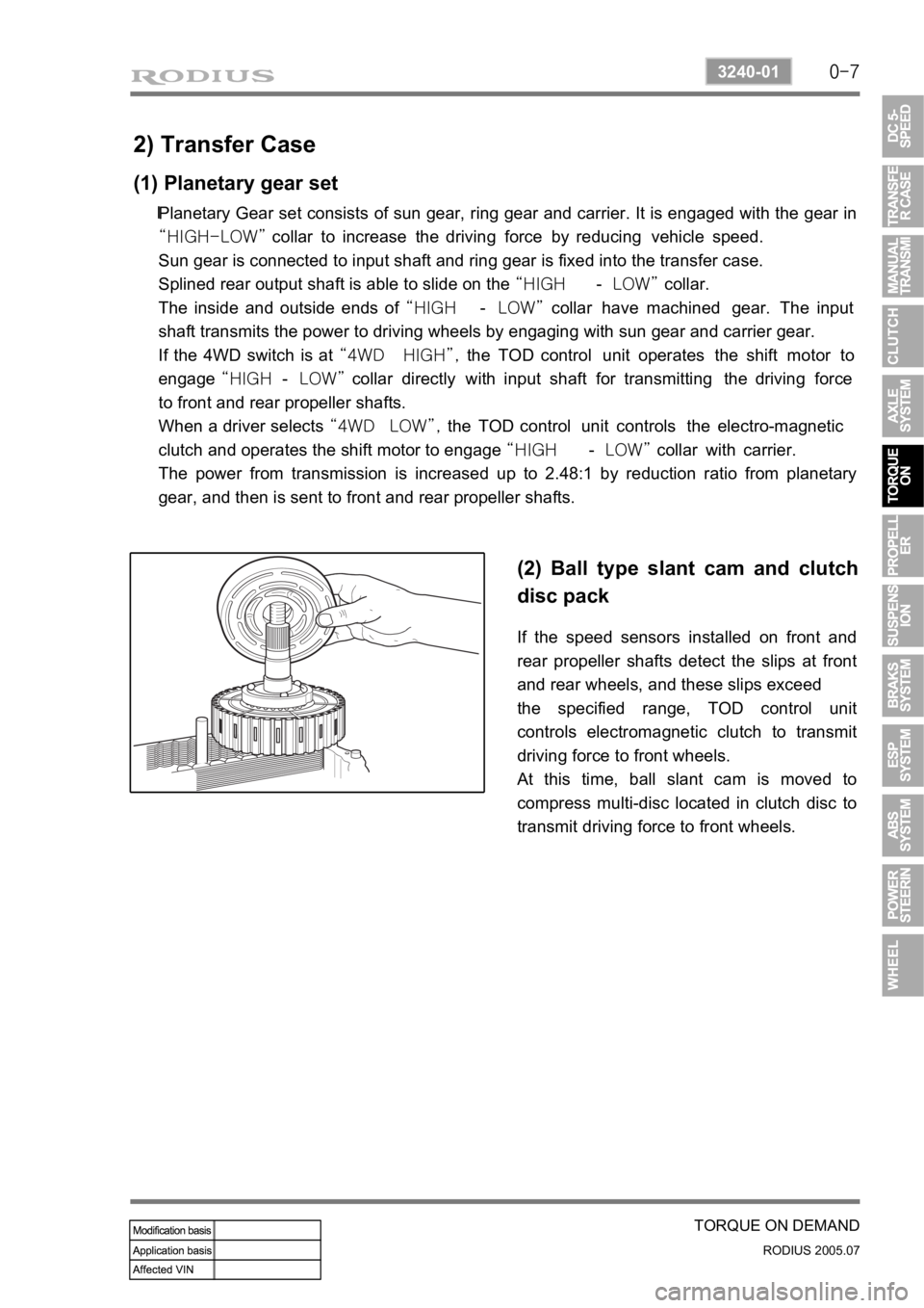
(2) Ball type slant cam and clutch
disc pack
If the speed sensors installed on front and
rear propeller shafts detect the slips at front
and rear wheels, and these slips exceed
the specified range, TOD control unit
controls electromagnetic clutch to transmit
driving force to front wheels.
At this time, ball slant cam is moved to
compress multi-disc located in clutch disc to
transmit driving force to front wheels.
Page 222 of 502
0-3
PROPELLER SHAFT
RODIUS 2005.07
3310-01
3310-01PROPELLER SHAFT
1. PROPELLER SHAFT GENERAL INFORMATION
The propeller shaft transfers the power through
the transmission and transfer case to the
front/rear axle differential carrier (final reduction
gear). It is manufactured by a thin rounded steel
pipe to have the strong resisting force against
the torsion and bending. Both ends of propelle
r
shaft are connected to the spider and the cente
r
of propeller shaft is connected to the spline to
accommodate the changes of the height and
length. The rubber bushing that covers the
intermediate bearing keeps the balance of rea
r
propeller shaft and absorbs its vibration.
2. SPECIFICATION
Page 356 of 502
0-4
RODIUS 2005.07
8010-10
CLUSTER
2. DESCRIPTIONS OF INDICATOR DISPLAY
1. Immobilizer indicator
2. Glow indicator
3. Winter mode indicator
4. Left turn signal indicator
5. Auto shift indicator (for automatic transmission)
6. Right turn signal indicator
7. Harzard indicator*
8. Engine check warning light
9. Cruise control indicator*
10. 4WD CHECK warning light
11. 4WD HIGH indicator
12. 4WD LOW indicator
13. Brake warning light14. Battery charge warning light
15. Seat belt reminder
16. Low fuel level warning light
17. Heated glass indicator
18. Door open warning light
19. High beam indicator
20. Engine oil pressure warning light
21. Air bag warning light
22. Water separator warning light
23. ABS warning light
24. EBD warning light
25. ESP warning light