Page 157 of 502

09-11
ENGINE CONTROL SYSTEM
RODIUS 2005.07
0452-01
No fuel is delivered by the fuel injectors when the ignition is off.
This prevents dieseling or engine run-on. Also, the fuel is not delivered if there are no reference
pulses received from the CKP sensor.
This prevents flooding.
8) Fuel Cut-Off Mode
Increasing the fuel injector pulse width.
Increasing the idle speed rpm.
Increasing the ignition dwell time. -
-
- When battery voltage is low, the ECM can compensate for a weak spark delivered by the
ignition module by using the following methods
7) Battery Voltage Correction Mode
3. EXHAUST SYSTEM
1) Catalytic Converter
The purpose of the catalytic converter is to convert the three pollutants of carbon
monoxide(CO), hydrocarbons (HC) and oxides of nitrogen (NOx) contained in the exhaust o
f
gasoline engines, into the harmless compounds of water (H2O), carbon dioxide (CO2) and
nitrogen (N2).
The catalytic converter contains a catalyst, a word coming from the Greek and which
designates the element essential for catalyst which triggers chemical reactions without itsel
f
being consumed.
These catalysts in the 3-way catalytic converter are the rare metals platinum (Pt) and rhodium
(Rh).
The catalytic converter consists essentially of three main elements.
The exhaust gases flow through the catalytic converter and, in so doing, coming into contact
with rare metals (Pt and Rh).
The following chemical reaction are produced.
CO + O2 → CO2
HC + O2 → CO2 + H2O
NOx → N2 + O2 -
-
-
Page 159 of 502
09-13
ENGINE CONTROL SYSTEM
RODIUS 2005.07
0452-01
When driving (part/full throttle), the servo motor controls the throttle valve in line with the
various load states and according to the input signals from the pedal value sensor according to
the input signals from the pedal value sensor according to the position of the accelerator pedal.
The function of the EA (electronic accelerator) in the ECM determines the opening angle of the
throttle valve through the throttle actuator.
Further functions areDriving ▶
Idle speed control
Cruise control
Reducing engine torque for ASR/ABS
operation
Electronic accelerator emergency running
Storing faults
Data transfer through CAN -
-
-
-
-
-
-
Page 161 of 502
09-15
ENGINE CONTROL SYSTEM
RODIUS 2005.07
0452-01
2) ECU (GSL G32)
IGN COIL, CPS, AIR FLOW SENSOR, THROTTLE SENSOR, TPS ▶
Page 162 of 502
09-16
RODIUS 2005.07
0452-01
ENGINE CONTROL SYSTEM
O2 SENSOR, PEDAL MODULE, CRUISE CONTROL SW, STOP LAMP SW ▶
Page 163 of 502
09-17
ENGINE CONTROL SYSTEM
RODIUS 2005.07
0452-01
INJECTOR, KNOCK SENSOR, IMMOBILIZER, CANISTER PURGE VALVE ▶
Page 164 of 502

0-3
DC 5-SPEED AUTOMATIC TRANSMISSION
RODIUS 2005.07
3650-01
2WD 4WD
3650-01DC 5-SPEED AUTOMATIC TRANSMISSION
1. OVERVIEW
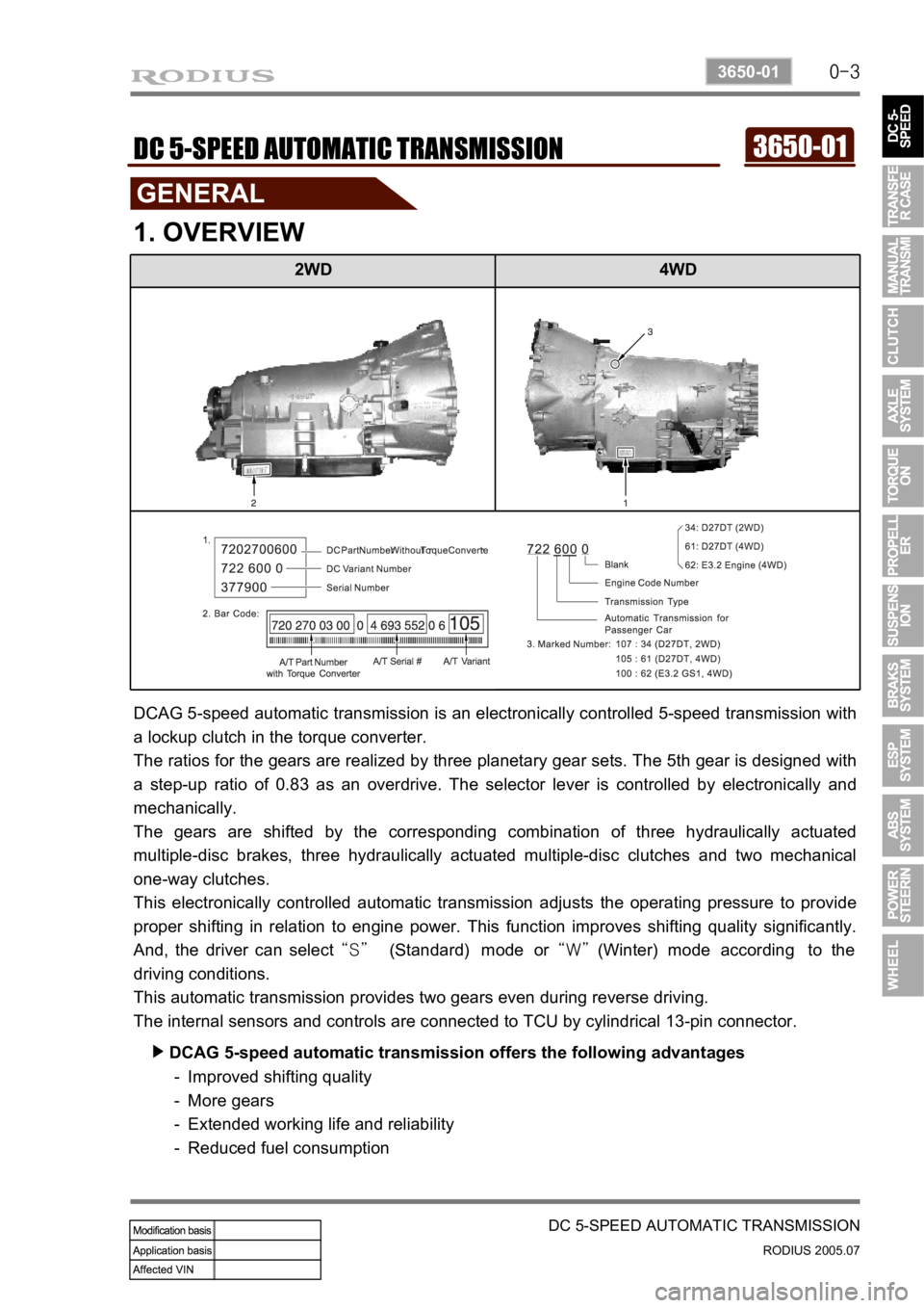
DCAG 5-speed automatic transmission is an electronically controlled 5-speed transmission with
a lockup clutch in the torque converter.
The ratios for the gears are realized by three planetary gear sets. The 5th gear is designed with
a step-up ratio of 0.83 as an overdrive. The selector lever is controlled by electronically and
mechanically.
The gears are shifted by the corresponding combination of three hydraulically actuated
multiple-disc brakes, three hydraulically actuated multiple-disc clutches and two mechanical
one-way clutches.
This electronically controlled automatic transmission adjusts the operating pressure to provide
proper shifting in relation to engine power. This function improves shifting quality significantly.
And, the driver can select “S” (Standard) mode or “W” (Winter) mode according to the
driving conditions.
This automatic transmission provides two gears even during reverse driving.
The internal sensors and controls are connected to TCU by cylindrical 13-pin connector.
DCAG 5-speed automatic transmission offers the following advantages ▶
Improved shifting quality
More gears
Extended working life and reliability
Reduced fuel consumption -
-
-
-
Page 199 of 502
0-17
TRANSFER CASE
RODIUS 2005.07
0000-00
This function is only available when the speed signal from speed sensor is about to stop
(below 2 km/h).
This function is only available when clutch pedal is depressed (manual transmission) o
r
selector lever is selected to “N” position (automatic transmission).
(TCCU must recognize the clutch pedal signal or “N” signal.)
Change the 4WD switch in instrument panel from 4H to 4L.
“4WD LOW” warning lamp in meter cluster blinks during this process, then remains
when the shift is completed.
“4WD CHECK” warning lamp comes on when the system is defective. -
-
-
-
- 4H → 4L ▶
Page 212 of 502

0-5
TORQUE ON DEMAND
RODIUS 2005.07
3240-01
2. GENERAL DESCRIPTION
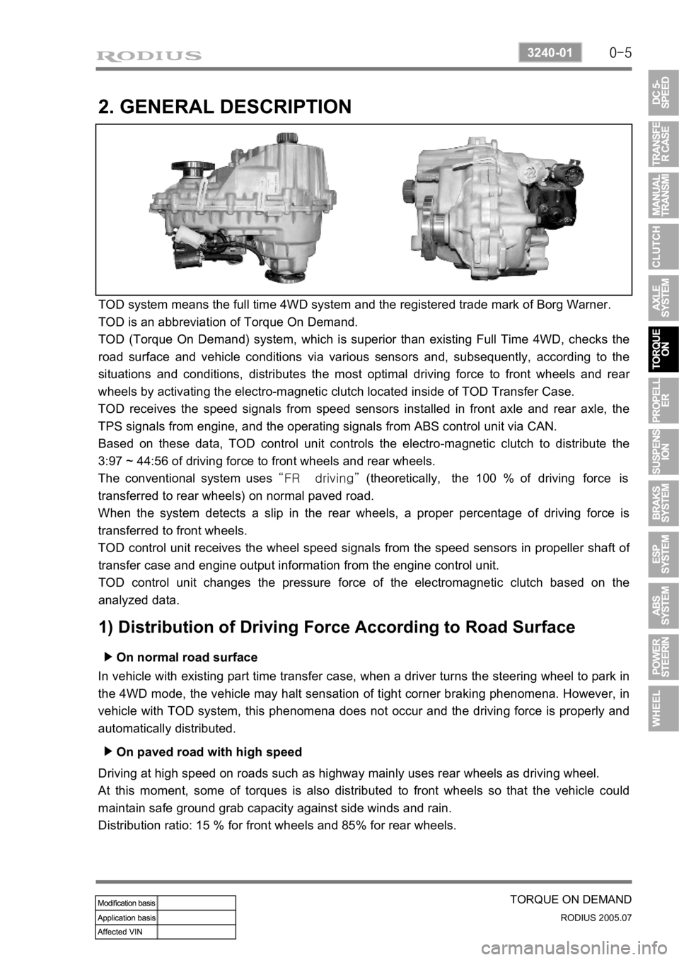
TOD system means the full time 4WD system and the registered trade mark of Borg Warner.
TOD is an abbreviation of Torque On Demand.
TOD (Torque On Demand) system, which is superior than existing Full Time 4WD, checks the
road surface and vehicle conditions via various sensors and, subsequently, according to the
situations and conditions, distributes the most optimal driving force to front wheels and rea
r
wheels by activating the electro-magnetic clutch located inside of TOD Transfer Case.
TOD receives the speed signals from speed sensors installed in front axle and rear axle, the
TPS signals from engine, and the operating signals from ABS control unit via CAN.
Based on these data, TOD control unit controls the electro-magnetic clutch to distribute the
3:97 ~ 44:56 of driving force to front wheels and rear wheels.
The conventional system uses “FR driving” (theoretically, the 100 % of driving force is
transferred to rear wheels) on normal paved road.
When the system detects a slip in the rear wheels, a proper percentage of driving force is
transferred to front wheels.
TOD control unit receives the wheel speed signals from the speed sensors in propeller shaft o
f
transfer case and engine output information from the engine control unit.
TOD control unit changes the pressure force of the electromagnetic clutch based on the
analyzed data.
1) Distribution of Driving Force According to Road Surface
On normal road surface ▶
In vehicle with existing part time transfer case, when a driver turns the steering wheel to park in
the 4WD mode, the vehicle may halt sensation of tight corner braking phenomena. However, in
vehicle with TOD system, this phenomena does not occur and the driving force is properly and
automatically distributed.
On paved road with high speed ▶
Driving at high speed on roads such as highway mainly uses rear wheels as driving wheel.
At this moment, some of torques is also distributed to front wheels so that the vehicle could
maintain safe ground grab capacity against side winds and rain.
Distribution ratio: 15 % for front wheels and 85% for rear wheels.