Page 205 of 502

0-4
RODIUS 2005.07
3010-01
CLUTCH
1. OVERVIEW
1) Driving Elements
The driving elements consist of two flat surfaces machined to a smooth finish.
One of these is the rear face of the engine flywheel and the other is the clutch cover pressure
plate. The clutch pressure plate is fitted into a clutch steel cover, which is bolted to the flywheel.
2) Driven Elements
The driven element is the clutch disc with a splined hub which is free to slide lengthwise along
the splines of the input shaft. The driving and driven elements are held in contact by spring
pressure. This pressure is exerted by a diaphragm spring in the clutch cover pressure plate
assembly.
3) Operating Elements
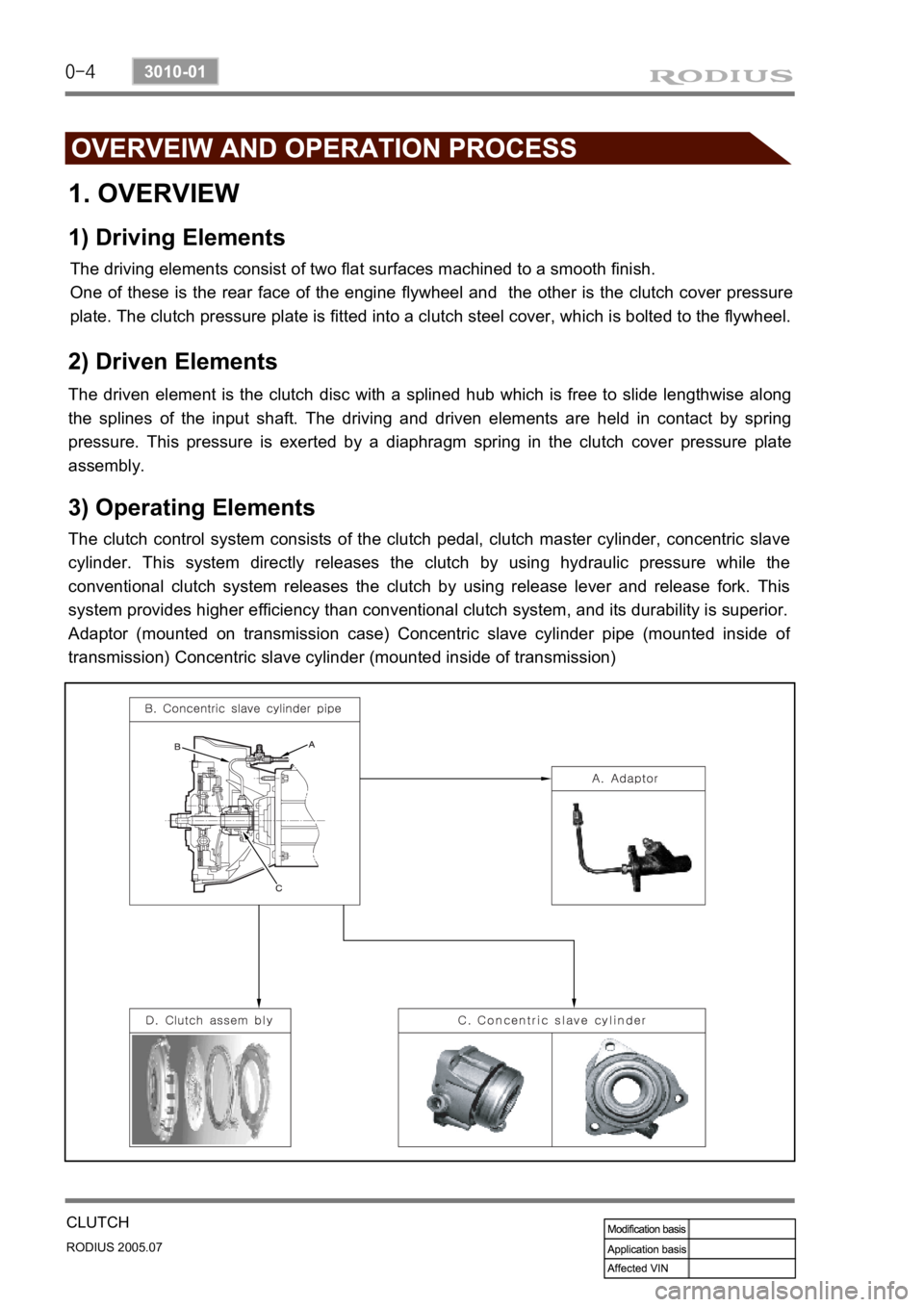
The clutch control system consists of the clutch pedal, clutch master cylinder, concentric slave
cylinder. This system directly releases the clutch by using hydraulic pressure while the
conventional clutch system releases the clutch by using release lever and release fork. This
system provides higher efficiency than conventional clutch system, and its durability is superior.
Adaptor (mounted on transmission case) Concentric slave cylinder pipe (mounted inside o
f
transmission) Concentric slave cylinder (mounted inside of transmission)
Page 206 of 502

0-5
CLUTCH
RODIUS 2005.07
3010-01
4) SAT (Self Adjusting Technology)
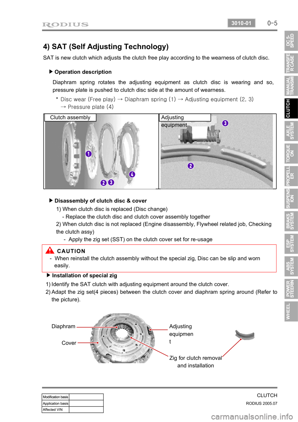
SAT is new clutch which adjusts the clutch free play according to the wearness of clutch disc. Operation description
▶
Diaphram spring rotates the adjusting equipment as clutch disc is wearing and so,
pressure plate is pushed to clutch disc side at the amount of wearness.
Disc wear (Free play) → Diaphram spring (1) → Adjusting equipme nt (2, 3)
→ Pressure plate (4)
*
Clutch assembly Adjusting
equipment
Disassembly of clutch disc & cover
▶
- When reinstall the clutch assembly without the special zig, Disc can be slip and worn
easily.
Installation of special zig
▶
Identify the SAT clutch with adjusting equipment around the clutch cover.
Adapt the zig set(4 pieces) between the clutch cover and diaphram spring around (Refer to
the picture).
1)
2)
Diaphram
Cover Zig for clutch removal and installationAdjusting
equipmen
t
1) When clutch disc is replaced (Disc change)
- Replace the clutch disc and clutch cover assembly together
2) When clutch disc is not replaced (Engine disassembly, Flywheel related job, Checking
the clutch assy)
- Apply the zig set (SST) on the clutch cover set for re-usage
Page 207 of 502
0-6
RODIUS 2005.07
3010-01
CLUTCH
Installation of special zig
▶
Identify the SAT clutch with adjusting equipment around the clutch cover.
Adapt the zig set(4 pieces) between the clutch cover and diaphram spring around (Refer to
the picture).
1)
2)
Diaphram
Cover Zig for clutch removal
and installation
Adjusting
equipment SST part number:D9930 0010C
Rexton applied SAC (Self Adjusting Clutch) system.
This clutch system also requires to replace both clutch cover and disc when the disc need to
be replaced. However, for
disc re-usage, special zig set is not necessary.
This is different point with SAT system.
Page 208 of 502
0-7
CLUTCH
RODIUS 2005.07
3010-01
2. COMPONENTS
1.Concentric slave cylinder cover 7. Hose 13. Switch
2. Concentric slave cylinder 8. Pipe 14. Bracket
3. Clutch cover 9. Clutch fluid chamber 15. Clutch pedal
4. Clutch disk 10. Clutch hydraulic line 16. Clutch pedal pad
5. Adaptor 11. Clutch pin (B)
6. Clutch master cylinder 12. Clutch housing
Page 212 of 502

0-5
TORQUE ON DEMAND
RODIUS 2005.07
3240-01
2. GENERAL DESCRIPTION
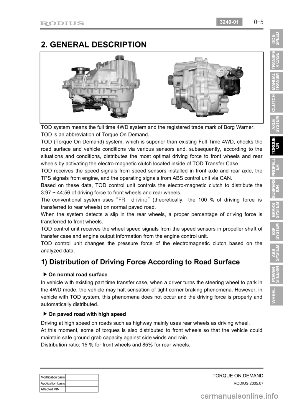
TOD system means the full time 4WD system and the registered trade mark of Borg Warner.
TOD is an abbreviation of Torque On Demand.
TOD (Torque On Demand) system, which is superior than existing Full Time 4WD, checks the
road surface and vehicle conditions via various sensors and, subsequently, according to the
situations and conditions, distributes the most optimal driving force to front wheels and rea
r
wheels by activating the electro-magnetic clutch located inside of TOD Transfer Case.
TOD receives the speed signals from speed sensors installed in front axle and rear axle, the
TPS signals from engine, and the operating signals from ABS control unit via CAN.
Based on these data, TOD control unit controls the electro-magnetic clutch to distribute the
3:97 ~ 44:56 of driving force to front wheels and rear wheels.
The conventional system uses “FR driving” (theoretically, the 100 % of driving force is
transferred to rear wheels) on normal paved road.
When the system detects a slip in the rear wheels, a proper percentage of driving force is
transferred to front wheels.
TOD control unit receives the wheel speed signals from the speed sensors in propeller shaft o
f
transfer case and engine output information from the engine control unit.
TOD control unit changes the pressure force of the electromagnetic clutch based on the
analyzed data.
1) Distribution of Driving Force According to Road Surface
On normal road surface ▶
In vehicle with existing part time transfer case, when a driver turns the steering wheel to park in
the 4WD mode, the vehicle may halt sensation of tight corner braking phenomena. However, in
vehicle with TOD system, this phenomena does not occur and the driving force is properly and
automatically distributed.
On paved road with high speed ▶
Driving at high speed on roads such as highway mainly uses rear wheels as driving wheel.
At this moment, some of torques is also distributed to front wheels so that the vehicle could
maintain safe ground grab capacity against side winds and rain.
Distribution ratio: 15 % for front wheels and 85% for rear wheels.
Page 214 of 502

0-7
TORQUE ON DEMAND
RODIUS 2005.07
3240-01
2) Transfer Case
(1) Planetary gear set
Planetary Gear set consists of sun gear, ring gear and carrier. It is engaged with the gear in
“HIGH-LOW” collar to increase the driving force by reducing vehicle speed.
Sun gear is connected to input shaft and ring gear is fixed into the transfer case.
Splined rear output shaft is able to slide on the “HIGH - LOW” collar.
The inside and outside ends of “HIGH - LOW” collar have machined gear. The input
shaft transmits the power to driving wheels by engaging with sun gear and carrier gear.
If the 4WD switch is at “4WD HIGH”, the TOD control unit operates the shift motor to
engage “HIGH - LOW” collar directly with input shaft for transmitting the driving force
to front and rear propeller shafts.
When a driver selects “4WD LOW”, the TOD control unit controls the electro-magnetic
clutch and operates the shift motor to engage “HIGH - LOW” collar with carrier.
The power from transmission is increased up to 2.48:1 by reduction ratio from planetary
gear, and then is sent to front and rear propeller shafts. null
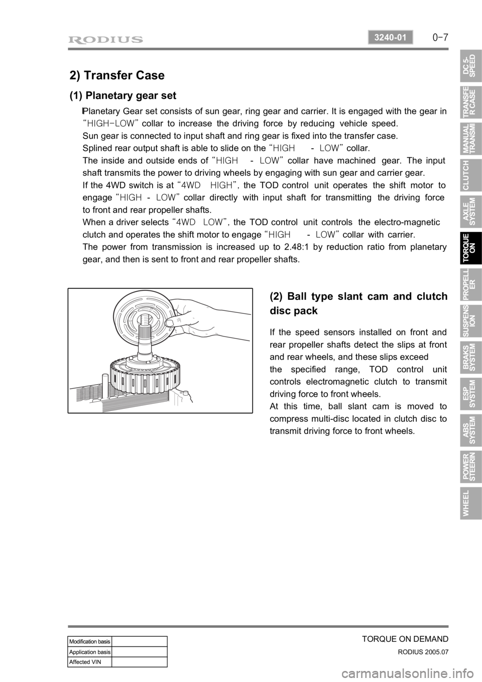
(2) Ball type slant cam and clutch
disc pack
If the speed sensors installed on front and
rear propeller shafts detect the slips at front
and rear wheels, and these slips exceed
the specified range, TOD control unit
controls electromagnetic clutch to transmit
driving force to front wheels.
At this time, ball slant cam is moved to
compress multi-disc located in clutch disc to
transmit driving force to front wheels.
Page 215 of 502
0-8
RODIUS 2005.07
3240-01
TORQUE ON DEMAND
(3) Electro Magnetic Clutch (EMC)
EMC consists of coil and housing. TOD control unit controls EMC by controlling duty cycle
according to the road and driving conditions. These controls use the continuity time and amount
of electric current to determine the torque to be transmitted to front wheels.
Basic controls in EMC ▶
Page:
< prev 1-8 9-16 17-24