Page 304 of 502
01-6
RODIUS 2005.07
8410-05
FUSE AND RELAY
3. ICM(INTEGRATED CONTROL MODULE) BOX
COMPARTMENT
The ICM box is installed along with RK STICS on the bracket behind the Instrument panel
undercover.
It contains an integrated module with around 14 relays according to the vehicle model. Relays
in the module are installed on the integrated circuit with a safety circuit. This system operates
with small current (by using transistor) and minimizes the sparks that occur during operations
(connection/disconnection) of relays; therefore its durability and wear resistance has been
greatly increased compared to the conventional relays.
Relays in the ICM box cannot be replaced respectively; so when the internal components
(including relay) are defective, ICM box should be replaced as an assembly.
RK STICS
ICM box
Page 355 of 502
0-3
CLUSTER
RODIUS 2005.07
8010-10
8010-01CLUSTER
1. APPEARANCE OF METER CLUSTER AND INDICATOR
DISPLAY
The instrument panel in this vehicle is different from conventional type of instrument panel. The
meter cluster and indicator display are separated. The meter cluster is located at the center o
f
the dash panel, and the indicator display is located in front of driver’s seat.
Meter cluster
Warning lamps and indicators
Page 398 of 502

0-8
RODIUS 2005.07
8790-04
PARKING AID SYSTEM
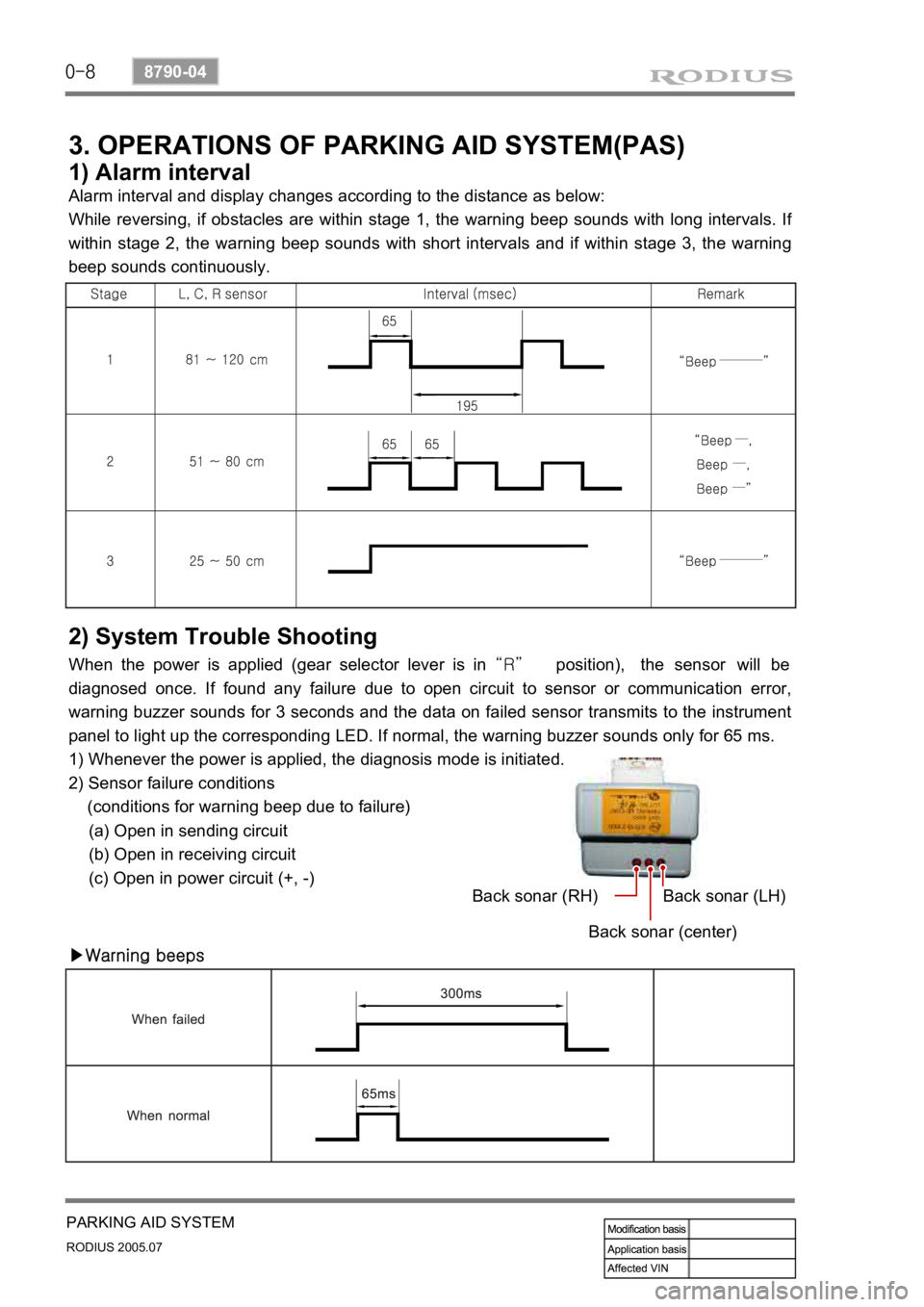
3. OPERATIONS OF PARKING AID SYSTEM(PAS)
1) Alarm interval
Alarm interval and display changes according to the distance as below:
While reversing, if obstacles are within stage 1, the warning beep sounds with long intervals. I
f
within stage 2, the warning beep sounds with short intervals and if within stage 3, the warning
beep sounds continuously.
2) System Trouble Shooting
When the power is applied (gear selector lever is in “R” position), the sensor will be
diagnosed once. If found any failure due to open circuit to sensor or communication error,
warning buzzer sounds for 3 seconds and the data on failed sensor transmits to the instrument
panel to light up the corresponding LED. If normal, the warning buzzer sounds only for 65 ms.
1) Whenever the power is applied, the diagnosis mode is initiated.
2) Sensor failure conditions
(conditions for warning beep due to failure)
(a) Open in sending circuit
(b) Open in receiving circuit
(c) Open in power circuit (+, -)
▶Warning beepsBack sonar (RH)
Back sonar (center)Back sonar (LH)
Page 413 of 502
0-4
RODIUS 2005.07
6810-20
AIR CONDITIONING SYSTEM
2. SYSTEM LAYOUT AND COMPONENTS
Front air conditioner module assembly - inside instrument panel
Page 422 of 502

0-13
AIR CONDITIONING SYSTEM
RODIUS 2005.07
6810-20
4. SENSORS AND ACTUATORS
1) Sun Sensor
It is installed on the upper left end of instrument panel. It is using characteristics that the
amount of current changes according to amount of light on the photosensitive surface. Photo
diode, converts the changes in light intensity into electrical changes, detects the amount of light
coming through windshield and changes it into current and then sends the signal to FATC
controller.
(1) Inspection
Remove the sun sensor and measure the current between terminals under sunlight.
Measure the current again under shade. It is in normal conditions if the measured value is
less than the measured value under sunlight.
Turn the ignition switch to “ON” position.
Measure the voltage to the sun sensor from FATC connector. (approx. 2.5 V under sunlight
and 4.8 V under shade.)
If the voltage value cannot be measured, check the circuit for open. If the measured value is
within the specified range, replace the FATC controller. 1.
2.
3.
4.
5.
Page 423 of 502
0-14
RODIUS 2005.07
6810-20
AIR CONDITIONING SYSTEM
2) Active Incar/Humidity Sensor (AIH Sensor)
The AIH sensor is installed at the driver side instrument panel undercover. It is a sensor that
detects interior temperature and humidity.
(1) Location
(2) Functions
Interior temperature sensor
▶
This sensor is a negative temperature coefficient (NTC) thermistor and detects the interio
r
temperature with air coming from senor hole and then sends the voltage value according to the
changed resistance to FATC controller.
Humidity sensor
▶
This sensor detects the interior humidity with humidity cell and then sends the voltage value
according to the changed humidity to FATC controller.
Humidity
sensor
Active incar sensor
(interior temperature
sensor)
Page 443 of 502

0-6
RODIUS 2005.07
8810-01
AIR BAG SYSTEM
3. AIRBAG FUNCTION DESCRIPTION
1) Bag (Cushion)
The airbag system performance is influenced on the cushion size, shape and position.
The cushion strength is a important parameter on the impact absorb effect.
Therefore, the control of the airbag performance depends on cushion size, shape, inflato
r
characteristic and vent hole size for the gas discharge.
The cushion’s material and folding function to control the cushion deployment
direction and the performance to protect passenger’s face. ·
·
·
·
2) Airbag Module
The driver airbag module is under the center pad of the steering wheel.
The passenger airbag module is installed in the instrument panel at passenger side.
The driver and passenger side airbag is inside each seat.
3) Module Cover/Housing
It is a type of a container that includes the cushion and the inflator.
The module housing functions to deliver the reaction force between the body structure and
the airbag (The airbag reaction is absorbed generally to the steering wheel or instrument
panel).
The module cover must be considered in a viewpoint of protection between exterior,
internal units and cushion. Also the module cover should be designed not to cause any
personal injury for deployment. ·
·
·
Do not disassemble the airbag module because unintentional deployment of the airbags
resulting from any damage or interference of the module can cause injury. -