GW-82
FRONT DOOR GLASS AND REGULATOR
Reset Operation
After installing each component to the vehicle, follow the steps
below.
1. Raise glass to the top position.
2. While pressing and holding reset switch, lower glass to the bot-
tom position.
3. Release reset switch, and check that reset switch returns to the
original position. Then raise glass to the top position.
CAUTION:
Do not operate glass automatically to raise glass to the top
position.
FITTING INSPECTION
�Check that glass is securely fit into glass run groove.
�While raising and lowering the window, check for abnormal operation.
�Lower the glass slightly [approx. 10 to 20 mm (0.39 to 0.79 in)], and check that the clearance to the sash
is parallel. If the clearance between the glass and sash is not parallel, loosen the regulator mounting bolts,
guide rail mounting bolts, and glass & carrier plate mounting bolts to correct the glass position.
PIIA0553E
DI-4
COMBINATION METERS
COMBINATION METERSPFP:24814
System DescriptionEKS00EGZ
UNIFIED CONTROL METER
�Speedometer, odo/trip meter, tachometer, fuel gauge and water temperature gauge are controlled by the
unified meter control unit, which is built into the combination meter.
�Digital meter is adopted for odo/trip meter.*
*The record of the odo meter is kept even if the battery cable is disconnected. The record of the trip meter
is erased when the battery cable is disconnected.
�Odo/trip meter segments can be checked in diagnosis mode.
�Meter/gauge can be checked in diagnosis mode.
HOW TO CHANGE THE DISPLAY FOR ODO/TRIP METER
�The vehicle speed signal and the memory signals from the meter memory circuit are processed by the
combination meter and the mileage is displayed.
�Ambient temperature indicator indicates signal from ambient sensor processed by combination meter.
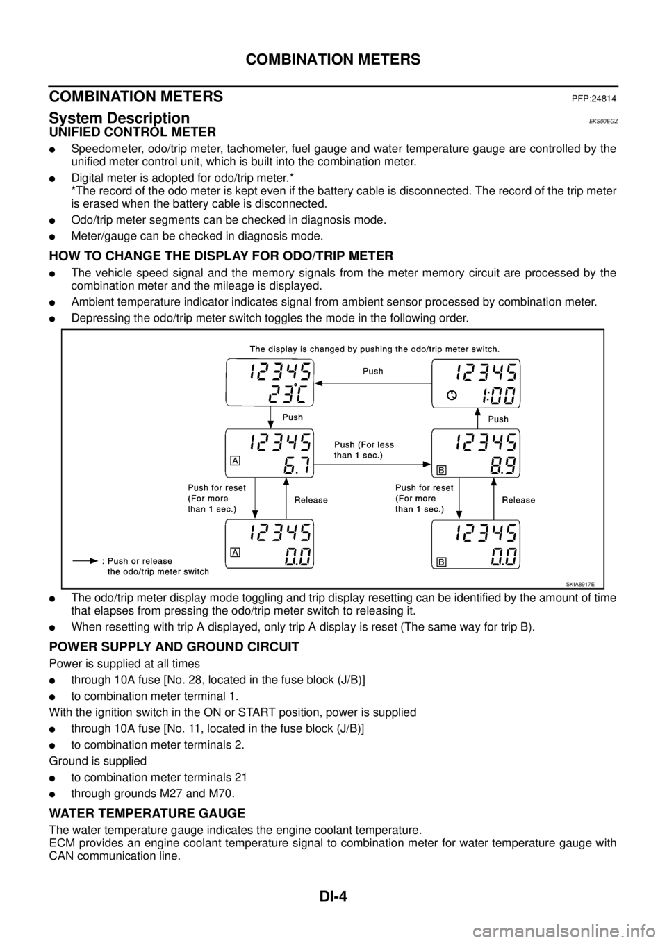
�Depressing the odo/trip meter switch toggles the mode in the following order.
�The odo/trip meter display mode toggling and trip display resetting can be identified by the amount of time
that elapses from pressing the odo/trip meter switch to releasing it.
�When resetting with trip A displayed, only trip A display is reset (The same way for trip B).
POWER SUPPLY AND GROUND CIRCUIT
Power is supplied at all times
�through 10A fuse [No. 28, located in the fuse block (J/B)]
�to combination meter terminal 1.
With the ignition switch in the ON or START position, power is supplied
�through 10A fuse [No. 11, located in the fuse block (J/B)]
�to combination meter terminals 2.
Ground is supplied
�to combination meter terminals 21
�through grounds M27 and M70.
WATER TEMPERATURE GAUGE
The water temperature gauge indicates the engine coolant temperature.
ECM provides an engine coolant temperature signal to combination meter for water temperature gauge with
CAN communication line.
SKIA8917E