Page 224 of 4555
EM-170
[YD22DDTi]
INJECTION TUBE AND FUEL INJECTOR
CAUTION:
�Check gutter spring in nozzle oil seal on fuel injector for missing.
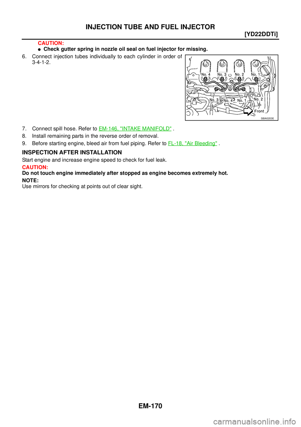
6. Connect injection tubes individually to each cylinder in order of
3-4-1-2.
7. Connect spill hose. Refer to EM-146, "
INTAKE MANIFOLD" .
8. Install remaining parts in the reverse order of removal.
9. Before starting engine, bleed air from fuel piping. Refer to FL-18, "
Air Bleeding" .
INSPECTION AFTER INSTALLATION
Start engine and increase engine speed to check for fuel leak.
CAUTION:
Do not touch engine immediately after stopped as engine becomes extremely hot.
NOTE:
Use mirrors for checking at points out of clear sight.
SBIA0203E
Page 231 of 4555
![NISSAN X-TRAIL 2005 Service Repair Manual FUEL PUMP
EM-177
[YD22DDTi]
C
D
E
F
G
H
I
J
K
L
MA
EM
11. Using the hexagon wrench (special service tool), tighten the
sprocket tightening bolt.
�When the washer of the fuel pump sprocket is removed](/manual-img/5/57403/w960_57403-230.png "NISSAN X-TRAIL 2005 Service Repair Manual FUEL PUMP
EM-177
[YD22DDTi]
C
D
E
F
G
H
I
J
K
L
MA
EM
11. Using the hexagon wrench (special service tool), tighten the
sprocket tightening bolt.
�When the washer of the fuel pump sprocket is removed")
FUEL PUMP
EM-177
[YD22DDTi]
C
D
E
F
G
H
I
J
K
L
MA
EM
11. Using the hexagon wrench (special service tool), tighten the
sprocket tightening bolt.
�When the washer of the fuel pump sprocket is removed,
install it with the marking “F” (front) facing the front of the
engine.
12. Pull out the positioning stopper pin (special service tool).
13. Install secondary timing chain. Refer to EM-193, "
Removal and Installation" .
14. Install injection tube center as follows: Refer to EM-167, "
INJECTION TUBE AND FUEL INJECTOR" .
a. Pre-set clip and insert rubber to injection tube center.
b. Pre-tight nut of injection tube center to fuel pump and fuel rail by hand. (until seal surface touched)
c. Adjust clip dimension and tight bolt for clip to intake manifold by tool.
d. Tight nut of injection tube center to fuel pump by tool.
e. Tight nut of injection tube center to fuel rail by tool.
15. Connect the harness connector to fuel pump.
16. Install fuel hoses.
17. Hereafter, install in the reverse order of removal.
18. Before starting engine, bleed air from fuel piping. Refer to FL-18, "
Air Bleeding" .
PBIC2404E
Page 233 of 4555
![NISSAN X-TRAIL 2005 Service Repair Manual ROCKER COVER
EM-179
[YD22DDTi]
C
D
E
F
G
H
I
J
K
L
MA
EM
�Loosen holding bolts in reverse order of that shown in the fig-
ure and remove.
6. Remove rocker cover gasket.
INSTALLATION
1. Apply 3.0 mm](/manual-img/5/57403/w960_57403-232.png "NISSAN X-TRAIL 2005 Service Repair Manual ROCKER COVER
EM-179
[YD22DDTi]
C
D
E
F
G
H
I
J
K
L
MA
EM
�Loosen holding bolts in reverse order of that shown in the fig-
ure and remove.
6. Remove rocker cover gasket.
INSTALLATION
1. Apply 3.0 mm")
ROCKER COVER
EM-179
[YD22DDTi]
C
D
E
F
G
H
I
J
K
L
MA
EM
�Loosen holding bolts in reverse order of that shown in the fig-
ure and remove.
6. Remove rocker cover gasket.
INSTALLATION
1. Apply 3.0 mm (0.118 in) dia. on locations shown in the figure.
�Use Genuine Liquid Gasket or equivalent.
2. Install rocker cover gasket to rocker cover.
3. Tighten holding bolts in numerical order shown in the figure.
Re-tighten to the same torque in the same order as above.
4. Install nozzle oil seal.
�Insert it straight until flange fully contacts rocker cover.
5. Install remaining parts in the reverse order of removal.
6. Before starting engine, bleed air from fuel piping. Refer to FL-18, "
Air Bleeding" .
INSPECTION AFTER INSTALLATION
Start engine and increase engine speed to check for fuel leak.
CAUTION:
Do not touch the engine immediately after stopped as engine becomes extremely hot.
NOTE:
Use mirrors for checking at points out of clear sight.
SBIA0175E
JEM248G
: 7.8 N·m (0.8 kg-m, 69 in-lb)
SBIA0175E
Page 239 of 4555
![NISSAN X-TRAIL 2005 Service Repair Manual CAMSHAFT
EM-185
[YD22DDTi]
C
D
E
F
G
H
I
J
K
L
MA
EM
�Install so that knock pins are positioned in the directions
shown in the figure.
NOTE:
Though camshaft does not stop at the location as shown in](/manual-img/5/57403/w960_57403-238.png "NISSAN X-TRAIL 2005 Service Repair Manual CAMSHAFT
EM-185
[YD22DDTi]
C
D
E
F
G
H
I
J
K
L
MA
EM
�Install so that knock pins are positioned in the directions
shown in the figure.
NOTE:
Though camshaft does not stop at the location as shown in")
CAMSHAFT
EM-185
[YD22DDTi]
C
D
E
F
G
H
I
J
K
L
MA
EM
�Install so that knock pins are positioned in the directions
shown in the figure.
NOTE:
Though camshaft does not stop at the location as shown in
the figure, for the placement of cam nose, it is generally
accepted that camshaft is placed at the same direction as
shown in the figure.
3. Install camshaft brackets.
�Completely remove any foreign material on back surfaces of camshaft brackets and top surface of cyl-
inder head.
�Install correctly, identifying brackets by the journal No. and
front mark on top surface.
4. Tighten bolts in the order shown in the figure according to the
following procedure:
a. Tighten all bolts.
�Make sure camshaft thrusting parts (on rear side) securely fit
in their mating parts on the cylinder head.
b. Tighten all bolts.
c. Tighten all bolts.
5. Install camshaft sprockets.
�Camshaft sprockets are commonly used for right side and left side.
�Align camshaft sprocket and knock pin on camshaft, and install.
�Holding the hexagonal part of camshaft with a wrench, tighten bolt securing camshaft sprocket.
6. Before installing spill tube after installing secondary timing chain, check and adjust valve clearance. Refer
to EM-185, "
Valve Clearance" .
7. Hereafter, install in the reverse order of removal.
8. Before starting engine, bleed air from fuel piping. Refer to FL-18, "
Air Bleeding" .
Va l v e C l e a r a n c eEBS00LRS
INSPECTION
�When the camshaft or parts in connection with valves are removed or replaced, and a malfunction has
occurred (poor starting, idling, or other malfunction) due to the misadjustment of the valve clearance,
inspect as follows.
�Inspect and adjust when the engine is cool (at normal temperature).
PBIC2026E
JEM175G
: 2 N·m (0.2 kg-m, 1 ft-lb)
: 6 N·m (0.6 kg-m, 4 ft-lb)
: 12.5 N·m (1.3 kg-m, 9 ft-lb)
JEM160G
Page 258 of 4555
EM-204
[YD22DDTi]
PRIMARY TIMING CHAIN
a. Apply a continuous bead of liquid gasket with the tube presser
(special service tool: WS39930000) on locations shown in the
figure.
Use Genuine Liquid Gasket or equivalent.
b. Install four O-rings to the grooves of the cylinder block and fuel
pump bracket.
c. Install rear chain case.
�When installing, align the dowel pin with the pin hole.A : Apply bead so that it does not protrude into the
oil passage.
B. C : Minimize overlapping area of bead, by starting
and ending at areas of bead as shown in the fig-
ure. Apply so that the portion marked.
D : Leave the start and end areas of the bead slightly
protruding from the case surface.
* : comes at an external location but cannot be
viewed externally after engine assembly.
PBIC1255E
JEM141G
Page 268 of 4555
![NISSAN X-TRAIL 2005 Service Repair Manual EM-214
[YD22DDTi]
CYLINDER HEAD
c. Tighten 180 degrees in numerical order as shown (angle tight-
ening).
d. Loosen completely in reverse order of that shown in the figure.
e. Tighten all bolts in nu](/manual-img/5/57403/w960_57403-267.png "NISSAN X-TRAIL 2005 Service Repair Manual EM-214
[YD22DDTi]
CYLINDER HEAD
c. Tighten 180 degrees in numerical order as shown (angle tight-
ening).
d. Loosen completely in reverse order of that shown in the figure.
e. Tighten all bolts in nu")
EM-214
[YD22DDTi]
CYLINDER HEAD
c. Tighten 180 degrees in numerical order as shown (angle tight-
ening).
d. Loosen completely in reverse order of that shown in the figure.
e. Tighten all bolts in numerical order as shown.
f. Tighten 90 degrees in numerical order as shown (angle tighten-
ing).
g. Tighten another 90 degrees in numerical order as shown (angle
tightening).
CAUTION:
�When the angle wrench (special service tool) is not used, paint an alignment mark on the head
of cylinder head bolt and cylinder head surface before tightening. Check the angle with a pro-
tractor.
4. Install glow plug.
CAUTION:
�To avoid damage, glow plugs should be removed only when required.
�Handle with care to avoid applying shock. When dropped from approx. 10 cm (3.94 in) or higher,
always replace with a new one.
�Before installing, remove carbon depositing on mounting hole of glow plug with a reamer.
5. Install in the reverse order of removal.
INSPECTION AFTER INSTALLATION
Inspection for Leaks
The following are procedures for checking fluids leak, lubricates leak and exhaust gases leak.
�Before starting engine, check oil/fluid levels including engine coolant and engine oil. If less than required
quantity, fill to the specified level. Refer to MA-17, "
RECOMMENDED FLUIDS AND LUBRICANTS" .
�Before starting engine, bleed air from fuel piping. Refer to FL-18, "Air Bleeding" .
�Run engine to check for unusual noise and vibration.
�Warm up engine thoroughly to make sure there is no leakage of fuel, exhaust gases, or any oil/fluids
including engine oil and engine coolant.
�Bleed air from lines and hoses of applicable lines, such as in cooling system.
�After cooling down engine, again check oil/fluid levels including engine oil and engine coolant. Refill to the
specified level, if necessary.
Summary of the inspection items:
* Transmission/transaxle/CVT fluid, power steering fluid, brake fluid, etc.
: 0 N·m (0 kg-m, 0 ft-lb)
:39.2 N·m (4.0 kg-m, 29 ft-lb)
JEM166G
Item Before starting engine Engine running After engine stopped
Engine coolant Level Leakage Level
Engine oil Level Leakage Level
Other oils and fluid* Level Leakage Level
Fuel Leakage Leakage Leakage
Exhaust gases — Leakage —
Page 273 of 4555
![NISSAN X-TRAIL 2005 Service Repair Manual CYLINDER HEAD
EM-219
[YD22DDTi]
C
D
E
F
G
H
I
J
K
L
MA
EM
5. Using the valve guide drift (commercial service tool), press fit
valve guides from camshaft side, referring to the dimension
shown in the](/manual-img/5/57403/w960_57403-272.png "NISSAN X-TRAIL 2005 Service Repair Manual CYLINDER HEAD
EM-219
[YD22DDTi]
C
D
E
F
G
H
I
J
K
L
MA
EM
5. Using the valve guide drift (commercial service tool), press fit
valve guides from camshaft side, referring to the dimension
shown in the")
CYLINDER HEAD
EM-219
[YD22DDTi]
C
D
E
F
G
H
I
J
K
L
MA
EM
5. Using the valve guide drift (commercial service tool), press fit
valve guides from camshaft side, referring to the dimension
shown in the figure.
CAUTION:
Cylinder head contains heat, when working, wear protective
equipment to avoid getting burned.
6. Using the valve guide reamer (commercial service tool), perform
reaming to the press-fitted valve guides.
Valve Seat Contact
�Before starting this check, confirm that the dimension of valve
guide and valves are as specified.
�Apply red lead primer on contacting surfaces of valves seat and
of valve face to examine the conditions of contacting surfaces.
�Make sure that the paint on contacting surfaces is continuous
along the entire circumference.
�If there are abnormal indications, grind the valve and check the
contact again. If malfunction indications still persist, replace
valve seat. Refer to EM-219, "
Valve Seat Replacement" .
Valve Seat Replacement
When removing valve seat, replace it with oversized [0.5 mm (0.020 in)] valve seat.
1. Bore out old seat until it collapses. Boring should not continue beyond the bottom face of the seat recess
in cylinder head. Set the machine depth stop to ensure this. Refer to EM-261, "
Va l v e S e a t" .
2. Ream cylinder head recess diameter for service valve seat.
�Be sure to ream in circles concentric to the valve guide center.
�This will enable valve seat to fit correctly.Projection length “H” : 10.4 - 10.6 mm (0.409 - 0.417 in)
PBIC2187E
Standard
Intake and Exhaust:
6.000 - 6.018 mm (0.2362 - 0.2369 in)
SEM932C
SBIA0322E
Oversize [0.5 mm (0.020 in)]:
Intake : 30.500 - 30.516 mm (1.2008 - 1.2014 in)
Exhaust : 29.500 - 29.516 mm (1.1614 - 1.1620 in)
SEM795A
Page 276 of 4555
![NISSAN X-TRAIL 2005 Service Repair Manual EM-222
[YD22DDTi]
ENGINE ASSEMBLY
ENGINE ASSEMBLYPFP:10001
Removal and Installation (2WD Models)EBS01FKK
WARNING:
�Situate vehicle on a flat and solid surface.
�Place chocks at front and back of rea](/manual-img/5/57403/w960_57403-275.png "NISSAN X-TRAIL 2005 Service Repair Manual EM-222
[YD22DDTi]
ENGINE ASSEMBLY
ENGINE ASSEMBLYPFP:10001
Removal and Installation (2WD Models)EBS01FKK
WARNING:
�Situate vehicle on a flat and solid surface.
�Place chocks at front and back of rea")
EM-222
[YD22DDTi]
ENGINE ASSEMBLY
ENGINE ASSEMBLYPFP:10001
Removal and Installation (2WD Models)EBS01FKK
WARNING:
�Situate vehicle on a flat and solid surface.
�Place chocks at front and back of rear wheels.
�For engines not equipped with engine slingers, attach proper slingers and bolts described in
PARTS CATALOG.
CAUTION:
�Always be careful to work safely, avoid forceful or uninstructed operations.
�Do not start working until exhaust system and engine coolant are cool enough.
�If items or work required are not covered by the engine main body section, refer to the applicable
sections.
�Always use the support point specified for lifting.
�Use either 2-pole lift type or separate type lift as best you can. If board-on type is used for
unavoidable reasons, support at the rear axle jacking point with transmission jack or similar tool
before starting work, in preparation for the backward shift of center of gravity.
�For supporting points for lifting and jacking point at rear axle, refer to GI-36, "Garage Jack and
Safety Stand" .
1. Rear engine mounting insulator 2. Rubber seat 3. Rear engine mounting bracket
4. RH engine mounting insulator 5. RH engine mounting bracket 6. Front engine mounting bracket
7. Front engine mounting insulator 8. Grommet 9. Center member
10. LH engine mounting insulator 11. Stopper 12. LH engine mounting bracket
PBIC3901E
![NISSAN X-TRAIL 2005 Service Repair Manual EM-204
[YD22DDTi]
PRIMARY TIMING CHAIN
a. Apply a continuous bead of liquid gasket with the tube presser
(special service tool: WS39930000) on locations shown in the
figure.
Use Genuine Liquid Gaske](/manual-img/5/57403/w960_57403-257.png "NISSAN X-TRAIL 2005 Service Repair Manual EM-204
[YD22DDTi]
PRIMARY TIMING CHAIN
a. Apply a continuous bead of liquid gasket with the tube presser
(special service tool: WS39930000) on locations shown in the
figure.
Use Genuine Liquid Gaske")