2005 NISSAN X-TRAIL check transmission fluid
[x] Cancel search: check transmission fluidPage 2265 of 4555

AT-1
AUTOMATIC TRANSAXLE
C TRANSMISSION/TRANSAXLE
CONTENTS
D
E
F
G
H
I
J
K
L
M
SECTION AT
A
B
AT
AUTOMATIC TRANSAXLE
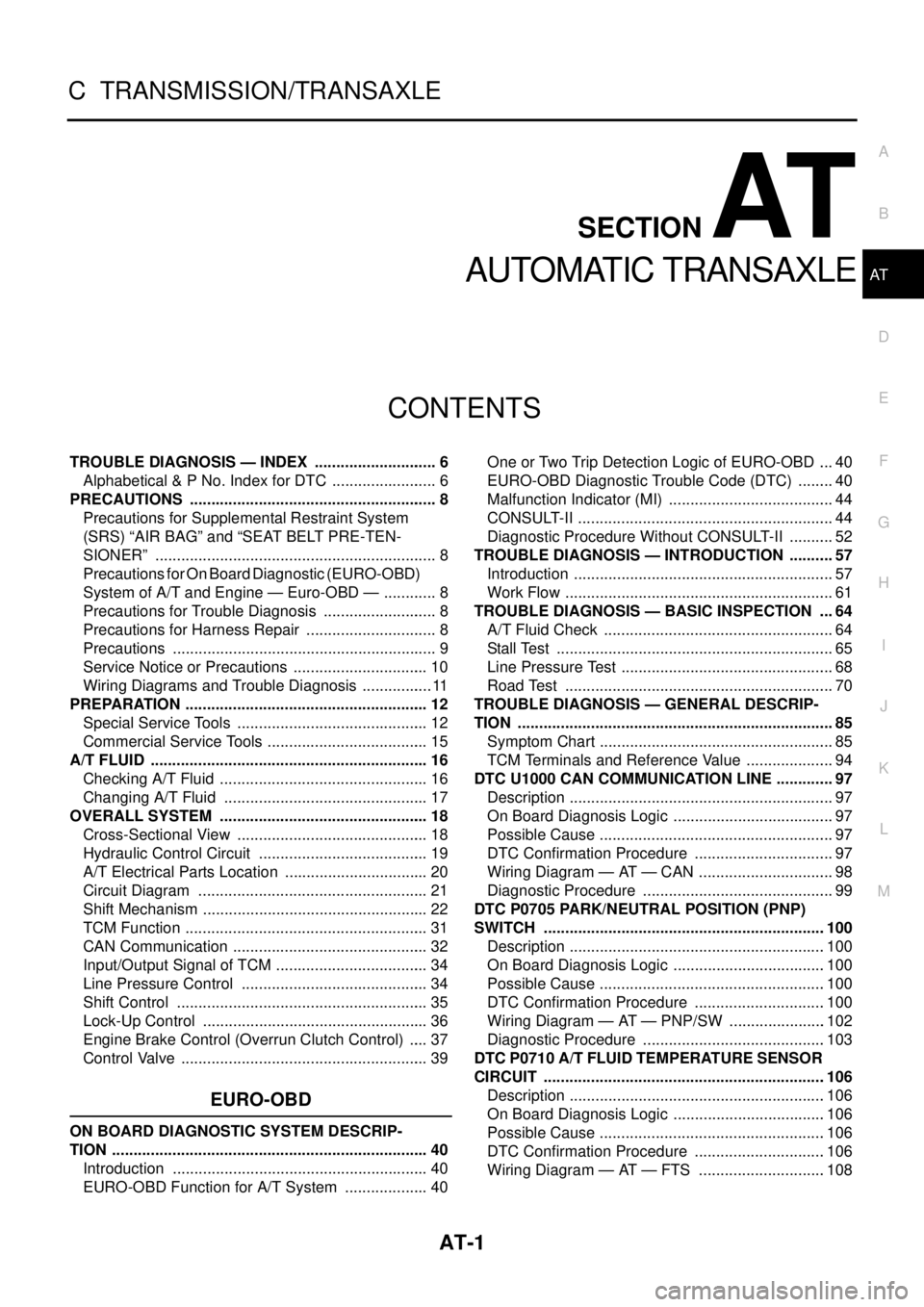
TROUBLE DIAGNOSIS — INDEX ............................. 6
Alphabetical & P No. Index for DTC ......................... 6
PRECAUTIONS .......................................................... 8
Precautions for Supplemental Restraint System
(SRS) “AIR BAG” and “SEAT BELT PRE-TEN-
SIONER” .................................................................. 8
Precautions for On Board Diagnostic (EURO-OBD)
System of A/T and Engine — Euro-OBD — ............. 8
Precautions for Trouble Diagnosis ........................... 8
Precautions for Harness Repair ............................... 8
Precautions .............................................................. 9
Service Notice or Precautions ................................ 10
Wiring Diagrams and Trouble Diagnosis ................. 11
PREPARATION ......................................................... 12
Special Service Tools ............................................. 12
Commercial Service Tools ...................................... 15
A/T FLUID ................................................................. 16
Checking A/T Fluid ................................................. 16
Changing A/T Fluid ................................................ 17
OVERALL SYSTEM ................................................. 18
Cross-Sectional View ............................................. 18
Hydraulic Control Circuit ........................................ 19
A/T Electrical Parts Location .................................. 20
Circuit Diagram ...................................................... 21
Shift Mechanism ..................................................... 22
TCM Function ......................................................... 31
CAN Communication .............................................. 32
Input/Output Signal of TCM .................................... 34
Line Pressure Control ............................................ 34
Shift Control ........................................................... 35
Lock-Up Control ..................................................... 36
Engine Brake Control (Overrun Clutch Control) ..... 37
Control Valve .......................................................... 39
EURO-OBD
ON BOARD DIAGNOSTIC SYSTEM DESCRIP-
TION .......................................................................... 40
Introduction ............................................................ 40
EURO-OBD Function for A/T System .................... 40One or Two Trip Detection Logic of EURO-OBD .... 40
EURO-OBD Diagnostic Trouble Code (DTC) ......... 40
Malfunction Indicator (MI) ....................................... 44
CONSULT-II ............................................................ 44
Diagnostic Procedure Without CONSULT-II ........... 52
TROUBLE DIAGNOSIS — INTRODUCTION ........... 57
Introduction ............................................................. 57
Work Flow ............................................................... 61
TROUBLE DIAGNOSIS — BASIC INSPECTION .... 64
A/T Fluid Check ...................................................... 64
Stall Test ................................................................. 65
Line Pressure Test .................................................. 68
Road Test ............................................................... 70
TROUBLE DIAGNOSIS — GENERAL DESCRIP-
TION .......................................................................... 85
Symptom Chart ....................................................... 85
TCM Terminals and Reference Value ..................... 94
DTC U1000 CAN COMMUNICATION LINE .............. 97
Description .............................................................. 97
On Board Diagnosis Logic ...................................... 97
Possible Cause ....................................................... 97
DTC Confirmation Procedure ................................. 97
Wiring Diagram — AT — CAN ................................ 98
Diagnostic Procedure ............................................. 99
DTC P0705 PARK/NEUTRAL POSITION (PNP)
SWITCH ..................................................................100
Description ............................................................100
On Board Diagnosis Logic ....................................100
Possible Cause .....................................................100
DTC Confirmation Procedure ...............................100
Wiring Diagram — AT — PNP/SW .......................102
Diagnostic Procedure ...........................................103
DTC P0710 A/T FLUID TEMPERATURE SENSOR
CIRCUIT ..................................................................106
Description ............................................................106
On Board Diagnosis Logic ....................................106
Possible Cause .....................................................106
DTC Confirmation Procedure ...............................106
Wiring Diagram — AT — FTS ..............................108
Page 4500 of 4555

MA-4
DESCRIPTION
DESCRIPTIONPFP:00000
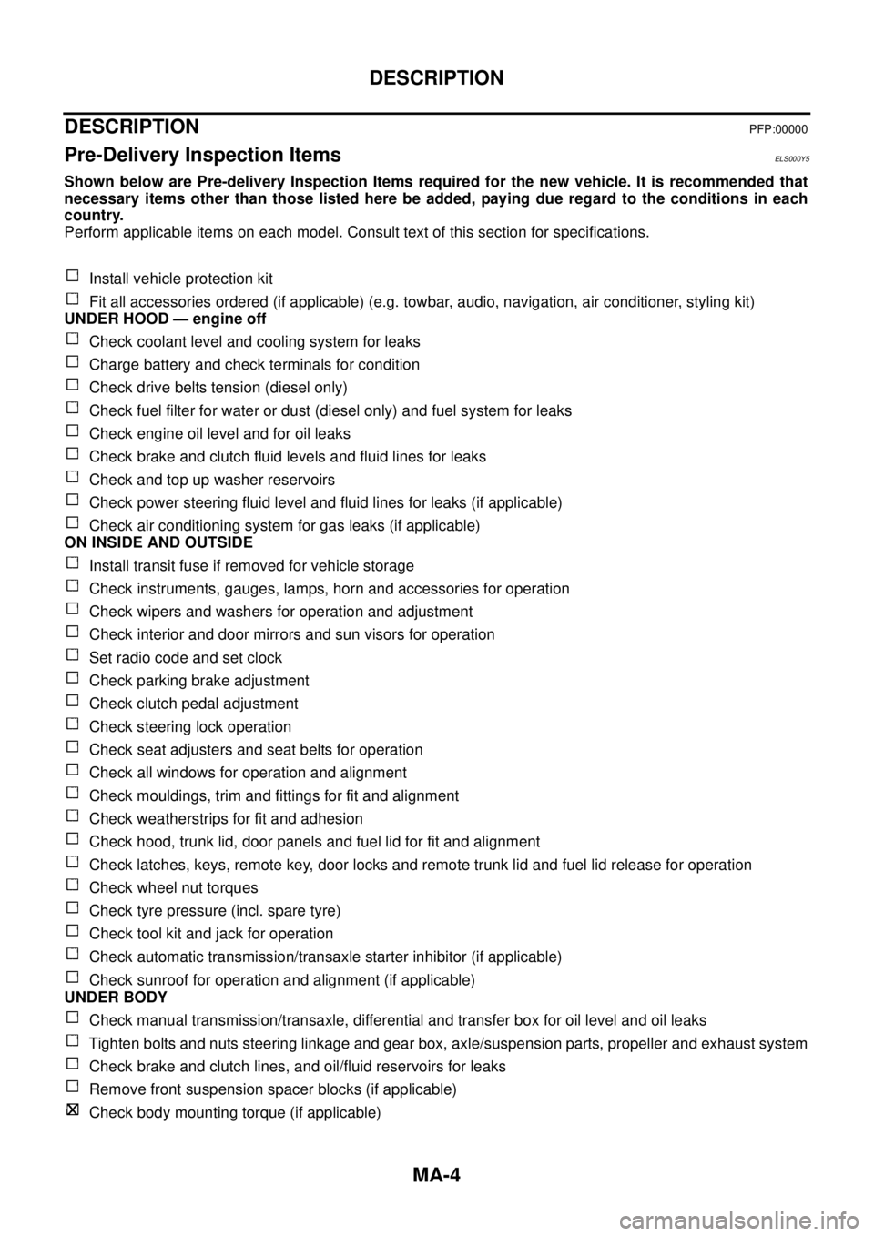
Pre-Delivery Inspection ItemsELS000Y5
Shown below are Pre-delivery Inspection Items required for the new vehicle. It is recommended that
necessary items other than those listed here be added, paying due regard to the conditions in each
country.
Perform applicable items on each model. Consult text of this section for specifications.
Install vehicle protection kit
Fit all accessories ordered (if applicable) (e.g. towbar, audio, navigation, air conditioner, styling kit)
UNDER HOOD — engine off
Check coolant level and cooling system for leaks
Charge battery and check terminals for condition
Check drive belts tension (diesel only)
Check fuel filter for water or dust (diesel only) and fuel system for leaks
Check engine oil level and for oil leaks
Check brake and clutch fluid levels and fluid lines for leaks
Check and top up washer reservoirs
Check power steering fluid level and fluid lines for leaks (if applicable)
Check air conditioning system for gas leaks (if applicable)
ON INSIDE AND OUTSIDE
Install transit fuse if removed for vehicle storage
Check instruments, gauges, lamps, horn and accessories for operation
Check wipers and washers for operation and adjustment
Check interior and door mirrors and sun visors for operation
Set radio code and set clock
Check parking brake adjustment
Check clutch pedal adjustment
Check steering lock operation
Check seat adjusters and seat belts for operation
Check all windows for operation and alignment
Check mouldings, trim and fittings for fit and alignment
Check weatherstrips for fit and adhesion
Check hood, trunk lid, door panels and fuel lid for fit and alignment
Check latches, keys, remote key, door locks and remote trunk lid and fuel lid release for operation
Check wheel nut torques
Check tyre pressure (incl. spare tyre)
Check tool kit and jack for operation
Check automatic transmission/transaxle starter inhibitor (if applicable)
Check sunroof for operation and alignment (if applicable)
UNDER BODY
Check manual transmission/transaxle, differential and transfer box for oil level and oil leaks
Tighten bolts and nuts steering linkage and gear box, axle/suspension parts, propeller and exhaust system
Check brake and clutch lines, and oil/fluid reservoirs for leaks
Remove front suspension spacer blocks (if applicable)
Check body mounting torque (if applicable)
Page 4548 of 4555

IDX-2
ALPHABETICAL INDEX
Numerics
4WD - Wiring diagram ....................................... TF-23
4WD control unit inspection table ...................... TF-30
A
A/C air flow ......................................... ATC-32
, MTC-5
A/C component layout ..................................... ATC-23
A/C compressor clutch removal and installation ...........
ATC-146
A/C compressor precaution ............................. ATC-10
A/C compressor special service tool ................ ATC-14
A/C diagnostic work flow (auto A/C) ................ ATC-34
A/C HFC134a (R134a) system precaution ........ ATC-4
A/C HFC134a (R134a) system service procedure .......
ATC-141
A/C HFC134a (R134a) system service tools ... ATC-15
A/C HFC134a system service equipment precaution ...
ATC-10
A/C lubricant (R134a) ...................................... ATC-24
A/C operational check ......................... ATC-65, MTC-7
A/C performance test diagnoses ..................... ATC-98
A/C reray .......................................................... ATC-94
A/C self-diagnoses (auto A/C) ......................... ATC-57
A/C system description (auto A/C) ................... ATC-27
A/C trouble diagnoses (auto A/C) ....... ATC-34, MTC-3
A/C, A - Wiring diagram ................................... ATC-39
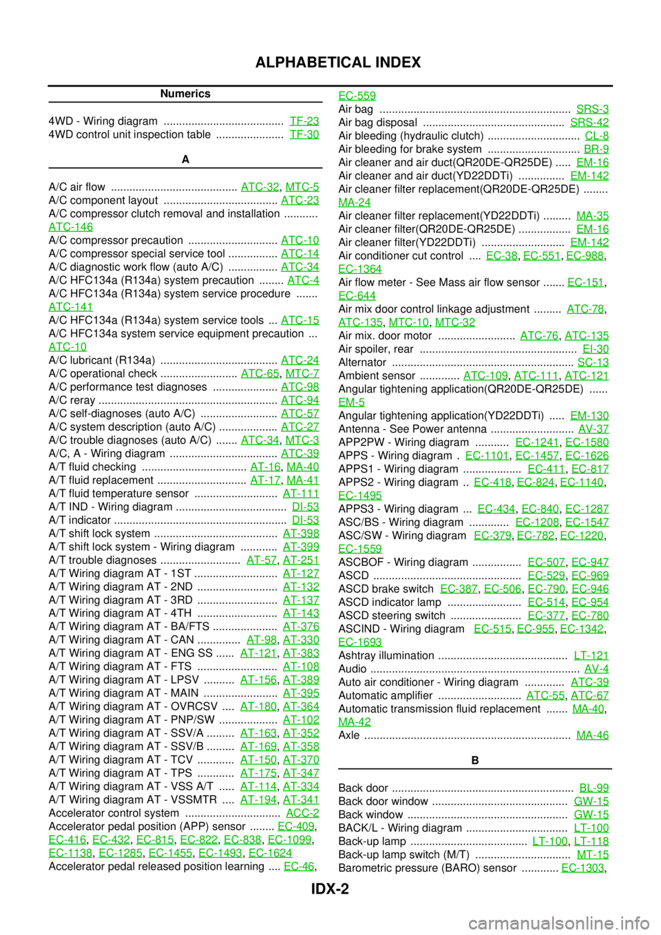
A/T fluid checking .................................. AT-16, MA-40
A/T fluid replacement ............................. AT-17, MA-41
A/T fluid temperature sensor ........................... AT-111
A/T IND - Wiring diagram .................................... DI-53
A/T indicator ........................................................ DI-53
A/T shift lock system ........................................ AT-398
A/T shift lock system - Wiring diagram ............ AT-399
A/T trouble diagnoses .......................... AT-57, AT-251
A/T Wiring diagram AT - 1ST ........................... AT-127
A/T Wiring diagram AT - 2ND .......................... AT-132
A/T Wiring diagram AT - 3RD .......................... AT-137
A/T Wiring diagram AT - 4TH .......................... AT-143
A/T Wiring diagram AT - BA/FTS ..................... AT-376
A/T Wiring diagram AT - CAN .............. AT-98, AT-330
A/T Wiring diagram AT - ENG SS ...... AT-121, AT-383
A/T Wiring diagram AT - FTS .......................... AT-108
A/T Wiring diagram AT - LPSV .......... AT-156, AT-389
A/T Wiring diagram AT - MAIN ........................ AT-395
A/T Wiring diagram AT - OVRCSV .... AT-180, AT-364
A/T Wiring diagram AT - PNP/SW ................... AT-102
A/T Wiring diagram AT - SSV/A ......... AT-163, AT-352
A/T Wiring diagram AT - SSV/B ......... AT-169, AT-358
A/T Wiring diagram AT - TCV ............ AT-150, AT-370
A/T Wiring diagram AT - TPS ............ AT-175, AT-347
A/T Wiring diagram AT - VSS A/T ..... AT-114, AT-334
A/T Wiring diagram AT - VSSMTR .... AT-194, AT-341
Accelerator control system ............................... ACC-2
Accelerator pedal position (APP) sensor ........ EC-409,
EC-416
, EC-432, EC-815, EC-822, EC-838, EC-1099,
EC-1138
, EC-1285, EC-1455, EC-1493, EC-1624
Accelerator pedal released position learning .... EC-46, EC-559
Air bag .............................................................. SRS-3
Air bag disposal .............................................. SRS-42
Air bleeding (hydraulic clutch) .............................. CL-8
Air bleeding for brake system .............................. BR-9
Air cleaner and air duct(QR20DE-QR25DE) ..... EM-16
Air cleaner and air duct(YD22DDTi) ............... EM-142
Air cleaner filter replacement(QR20DE-QR25DE) ........
MA-24
Air cleaner filter replacement(YD22DDTi) ......... MA-35
Air cleaner filter(QR20DE-QR25DE) ................. EM-16
Air cleaner filter(YD22DDTi) ........................... EM-142
Air conditioner cut control .... EC-38, EC-551, EC-988,
EC-1364
Air flow meter - See Mass air flow sensor ....... EC-151,
EC-644
Air mix door control linkage adjustment ......... ATC-78,
ATC-135
, MTC-10, MTC-32
Air mix. door motor ......................... ATC-76, ATC-135
Air spoiler, rear ................................................... EI-30
Alternator ........................................................... SC-13
Ambient sensor ............. ATC-109, ATC-111, ATC-121
Angular tightening application(QR20DE-QR25DE) ......
EM-5
Angular tightening application(YD22DDTi) ..... EM-130
Antenna - See Power antenna ........................... AV-37
APP2PW - Wiring diagram ........... EC-1241, EC-1580
APPS - Wiring diagram . EC-1101, EC-1457, EC-1626
APPS1 - Wiring diagram ................... EC-411, EC-817
APPS2 - Wiring diagram .. EC-418, EC-824, EC-1140,
EC-1495
APPS3 - Wiring diagram ... EC-434, EC-840, EC-1287
ASC/BS - Wiring diagram ............. EC-1208, EC-1547
ASC/SW - Wiring diagram EC-379, EC-782, EC-1220,
EC-1559
ASCBOF - Wiring diagram ................ EC-507, EC-947
ASCD ................................................ EC-529, EC-969
ASCD brake switch EC-387, EC-506, EC-790, EC-946
ASCD indicator lamp ........................ EC-514, EC-954
ASCD steering switch ....................... EC-377, EC-780
ASCIND - Wiring diagram EC-515, EC-955, EC-1342,
EC-1693
Ashtray illumination .......................................... LT-121
Audio .................................................................... AV-4
Auto air conditioner - Wiring diagram ............. ATC-39
Automatic amplifier ........................... ATC-55, ATC-67
Automatic transmission fluid replacement ....... MA-40,
MA-42
Axle ................................................................... MA-46
B
Back door ........................................................... BL-99
Back door window ............................................ GW-15
Back window .................................................... GW-15
BACK/L - Wiring diagram ................................. LT-100
Back-up lamp ...................................... LT-100, LT-118
Back-up lamp switch (M/T) ............................... MT-15
Barometric pressure (BARO) sensor ............ EC-1303,