Page 2821 of 4555
ALL MODE 4X4 SYSTEM
TF-17
C
E
F
G
H
I
J
K
L
MA
B
TF
TYPE 4/TYPE 5
System diagram
Input/output signal chart
T: Transmit R: Receive ASCD SET lamp signal TR
ASCD CRUISE lamp signal TR Signals ECM TCMABS actuator
and electric unit
(control unit)4WD control
unitCombination
meter
PKIA9634E
Signals ECMESP/TCS/ABS
control unitSteering angle
sensor4WD control
unitCombination
meter
4WD mode indicator lamp signalTR
4WD warning lamp signalTR
A/C compressor feedback signal*
2TR
A/C switch signal*
1RT
ABS warning lamp signal T R
Accelerator pedal position signal T R R
Brake warning lamp signal T R
Engine coolant temperature signal TR
Engine speed signal T R R R
ESP OFF indicator lamp signal T R
Glow indicator lamp signal*1 TR
MI signal TR
Stop lamp switch signal T R
Vehicle speed signalTRR
RT
SLIP indicator lamp signal T R
Parking brake switch signalRT
Steering angle sensor signal R T
ASCD SET lamp signal TR
ASCD CRUISE lamp signal TR
Page 2822 of 4555
TF-18
ALL MODE 4X4 SYSTEM
*1: YD engine models only
*2: QR engine models only
TYPE 6
System diagram
Input/output signal chart
T: Transmit R: Receive
PKIA9635E
Signals ECM TCMESP/TCS/
ABS control
unitSteering
angle sensor4WD control
unitCombination
meter
4WD mode indicator lamp signalTR
4WD warning lamp signalTR
A/C compressor feedback signal TR
A/T position indicator lamp signal T R R
A/T self-diagnosis signal R T
ABS warning lamp signal T R
Accelerator pedal position signal T R R
Brake warning lamp signal T R
Closed throttle position signal T R
Engine and A/T integratedTR
RT
Engine coolant temperature signal TR
Engine speed signal T R R R
ESP OFF indicator lamp signal T R
MI signal TR
O/D OFF indicator signal T R
Output shaft revolution signal R T
Overdrive control switch signal R T
P·N range signal R T
SLIP indicator lamp signal T R
Steering angle sensor signal R T
Page 2823 of 4555
ALL MODE 4X4 SYSTEM
TF-19
C
E
F
G
H
I
J
K
L
MA
B
TF
Stop lamp switch signalRT
TR
Vehicle speed signalTRR
RT
Parking brake switch signalRT
Wide open throttle position signal T R
ASCD SET lamp signal TR
ASCD CRUISE lamp signal TR Signals ECM TCMESP/TCS/
ABS control
unitSteering
angle sensor4WD control
unitCombination
meter
Page 2824 of 4555
TF-20
TROUBLE DIAGNOSIS
TROUBLE DIAGNOSISPFP:00004
Fail-Safe FunctionEDS001VE
�If any malfunction occurs in 4WD electrical system, and control unit detects the malfunction, 4WD warning
lamp on combination meter turns ON to indicate system malfunction.
�When 4WD warning lamp is ON, vehicle changes to front-wheel drive or shifting driving force-4WD (Rear-
wheels still have some driving torque).
How to Perform Trouble DiagnosisEDS001VF
BASIC CONCEPT
�To perform trouble diagnosis, it is the most important to have understanding about vehicle systems (con-
trol and mechanism) thoroughly.
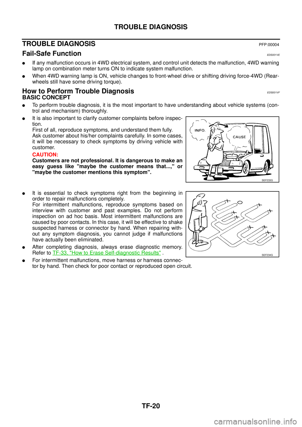
�It is also important to clarify customer complaints before inspec-
tion.
First of all, reproduce symptoms, and understand them fully.
Ask customer about his/her complaints carefully. In some cases,
it will be necessary to check symptoms by driving vehicle with
customer.
CAUTION:
Customers are not professional. It is dangerous to make an
easy guess like "maybe the customer means that...," or
"maybe the customer mentions this symptom".
�It is essential to check symptoms right from the beginning in
order to repair malfunctions completely.
For intermittent malfunctions, reproduce symptoms based on
interview with customer and past examples. Do not perform
inspection on ad hoc basis. Most intermittent malfunctions are
caused by poor contacts. In this case, it will be effective to shake
suspected harness or connector by hand. When repairing with-
out any symptom diagnosis, you cannot judge if malfunctions
have actually been eliminated.
�After completing diagnosis, always erase diagnostic memory.
Refer to TF-33, "
How to Erase Self-diagnostic Results" .
�For intermittent malfunctions, move harness or harness connec-
tor by hand. Then check for poor contact or reproduced open circuit.
SEF233G
SEF234G
Page 2851 of 4555
TROUBLE DIAGNOSIS FOR SYMPTOMS
TF-47
C
E
F
G
H
I
J
K
L
MA
B
TF
3. CHECK 4WD CONTROL UNIT GROUND CIRCUIT
1. Turn ignition switch “OFF”.
2. Disconnect 4WD control unit harness connector.
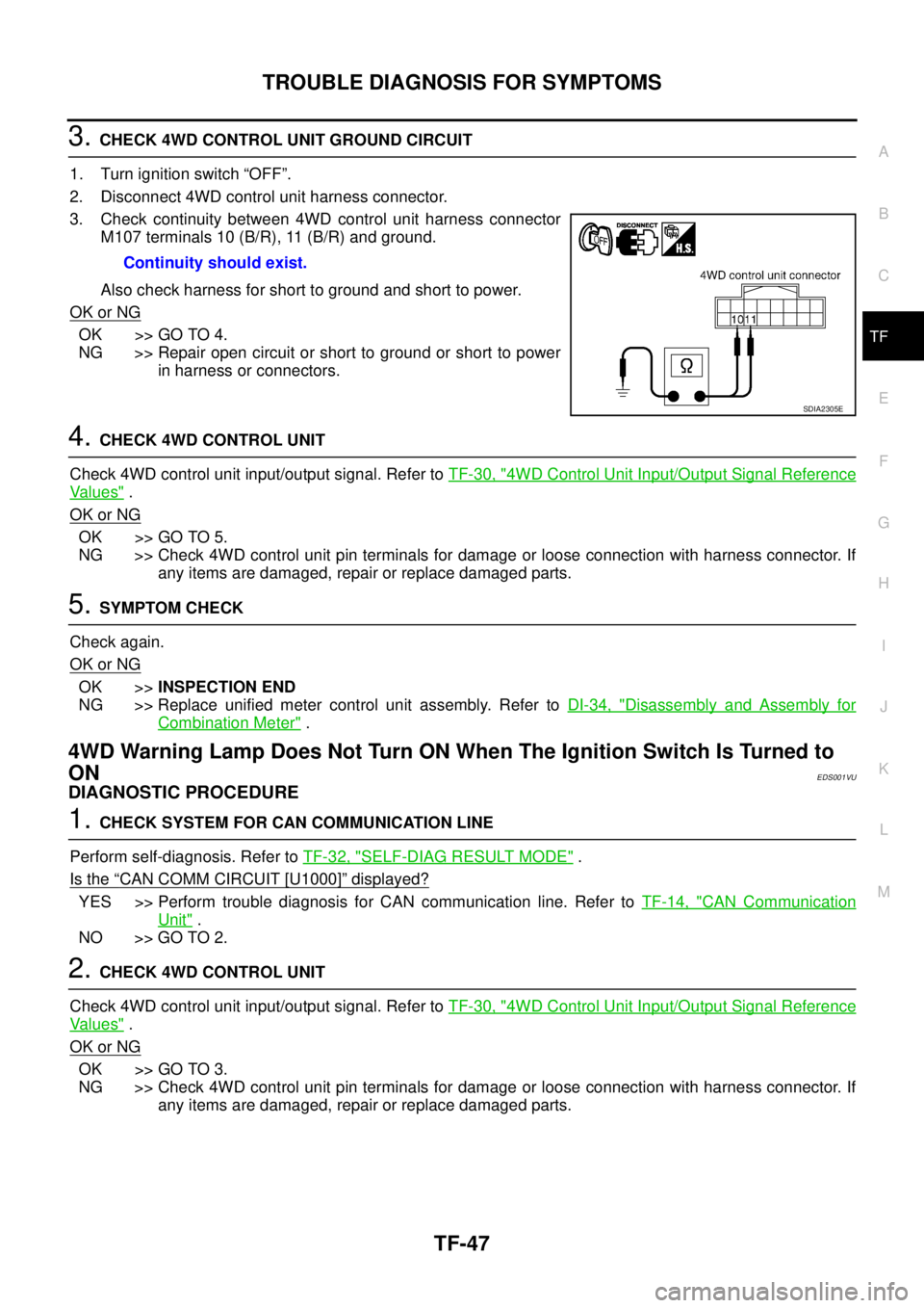
3. Check continuity between 4WD control unit harness connector
M107 terminals 10 (B/R), 11 (B/R) and ground.
Also check harness for short to ground and short to power.
OK or NG
OK >> GO TO 4.
NG >> Repair open circuit or short to ground or short to power
in harness or connectors.
4. CHECK 4WD CONTROL UNIT
Check 4WD control unit input/output signal. Refer to TF-30, "
4WD Control Unit Input/Output Signal Reference
Va l u e s" .
OK or NG
OK >> GO TO 5.
NG >> Check 4WD control unit pin terminals for damage or loose connection with harness connector. If
any items are damaged, repair or replace damaged parts.
5. SYMPTOM CHECK
Check again.
OK or NG
OK >>INSPECTION END
NG >> Replace unified meter control unit assembly. Refer to DI-34, "
Disassembly and Assembly for
Combination Meter" .
4WD Warning Lamp Does Not Turn ON When The Ignition Switch Is Turned to
ON
EDS001VU
DIAGNOSTIC PROCEDURE
1. CHECK SYSTEM FOR CAN COMMUNICATION LINE
Perform self-diagnosis. Refer to TF-32, "
SELF-DIAG RESULT MODE" .
Is the
“CAN COMM CIRCUIT [U1000]” displayed?
YES >> Perform trouble diagnosis for CAN communication line. Refer to TF-14, "CAN Communication
Unit" .
NO >> GO TO 2.
2. CHECK 4WD CONTROL UNIT
Check 4WD control unit input/output signal. Refer to TF-30, "
4WD Control Unit Input/Output Signal Reference
Va l u e s" .
OK or NG
OK >> GO TO 3.
NG >> Check 4WD control unit pin terminals for damage or loose connection with harness connector. If
any items are damaged, repair or replace damaged parts. Continuity should exist.
SDIA2305E
Page 2852 of 4555
TF-48
TROUBLE DIAGNOSIS FOR SYMPTOMS
3. SYMPTOM CHECK
Check again.
OK or NG
OK >>INSPECTION END
NG >> Replace unified meter control unit assembly. Refer to DI-34, "
Disassembly and Assembly for
Combination Meter" .
4WD Warning Lamp Does Not Turn OFF Several Seconds after Engine StartedEDS001VV
DIAGNOSTIC PROCEDURE
1. CHECK SELF-DIAGNOSTIC RESULTS
Perform self-diagnosis. Refer to TF-32, "
SELF-DIAG RESULT MODE" .
Is any malfunction detected by self-diagnosis?
YES >> Check the malfunctioning system.
NO >> GO TO 2.
2. CHECK 4WD CONTROL UNIT POWER SUPPLY CIRCUIT
1. Turn ignition switch “OFF”.
2. Disconnect 4WD control unit harness connector.
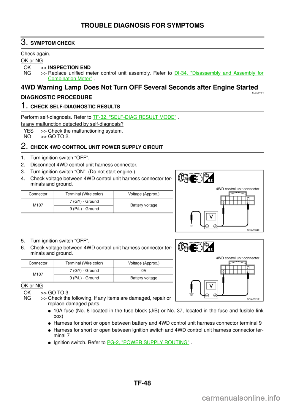
3. Turn ignition switch “ON”. (Do not start engine.)
4. Check voltage between 4WD control unit harness connector ter-
minals and ground.
5. Turn ignition switch “OFF”.
6. Check voltage between 4WD control unit harness connector ter-
minals and ground.
OK or NG
OK >> GO TO 3.
NG >> Check the following. If any items are damaged, repair or
replace damaged parts.
�10A fuse (No. 8 located in the fuse block (J/B) or No. 37, located in the fuse and fusible link
box)
�Harness for short or open between battery and 4WD control unit harness connector terminal 9
�Harness for short or open between ignition switch and 4WD control unit harness connector ter-
minal 7
�Ignition switch. Refer to PG-2, "POWER SUPPLY ROUTING" .
Connector Terminal (Wire color) Voltage (Approx.)
M1077 (GY) - Ground
Battery voltage
9 (P/L) - Ground
SDIA2304E
Connector Terminal (Wire color) Voltage (Approx.)
M1077 (GY) - Ground 0V
9 (P/L) - Ground Battery voltage
SDIA2321E
Page 2853 of 4555
TROUBLE DIAGNOSIS FOR SYMPTOMS
TF-49
C
E
F
G
H
I
J
K
L
MA
B
TF
3. CHECK 4WD CONTROL UNIT GROUND CIRCUIT
1. Turn ignition switch “OFF”.
2. Disconnect 4WD control unit harness connector.
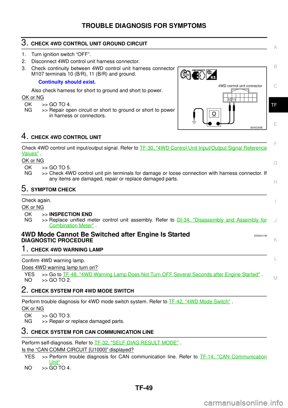
3. Check continuity between 4WD control unit harness connector
M107 terminals 10 (B/R), 11 (B/R) and ground.
Also check harness for short to ground and short to power.
OK or NG
OK >> GO TO 4.
NG >> Repair open circuit or short to ground or short to power
in harness or connectors.
4. CHECK 4WD CONTROL UNIT
Check 4WD control unit input/output signal. Refer to TF-30, "
4WD Control Unit Input/Output Signal Reference
Va l u e s" .
OK or NG
OK >> GO TO 5.
NG >> Check 4WD control unit pin terminals for damage or loose connection with harness connector. If
any items are damaged, repair or replace damaged parts.
5. SYMPTOM CHECK
Check again.
OK or NG
OK >>INSPECTION END
NG >> Replace unified meter control unit assembly. Refer to DI-34, "
Disassembly and Assembly for
Combination Meter" .
4WD Mode Cannot Be Switched after Engine Is StartedEDS001VW
DIAGNOSTIC PROCEDURE
1. CHECK 4WD WARNING LAMP
Confirm 4WD warning lamp.
Does 4WD warning lamp turn on?
YES >> Go to TF-48, "4WD Warning Lamp Does Not Turn OFF Several Seconds after Engine Started" .
NO >> GO TO 2.
2. CHECK SYSTEM FOR 4WD MODE SWITCH
Perform trouble diagnosis for 4WD mode switch system. Refer to TF-42, "
4WD Mode Switch" .
OK or NG
OK >> GO TO 3.
NG >> Repair or replace damaged parts.
3. CHECK SYSTEM FOR CAN COMMUNICATION LINE
Perform self-diagnosis. Refer to TF-32, "
SELF-DIAG RESULT MODE" .
Is the
“CAN COMM CIRCUIT [U1000]” displayed?
YES >> Perform trouble diagnosis for CAN communication line. Refer to TF-14, "CAN Communication
Unit" .
NO >> GO TO 4.Continuity should exist.
SDIA2305E
Page 2854 of 4555
TF-50
TROUBLE DIAGNOSIS FOR SYMPTOMS
4. CHECK 4WD CONTROL UNIT
Check 4WD control unit input/output signal. Refer to TF-30, "
4WD Control Unit Input/Output Signal Reference
Va l u e s" .
OK or NG
OK >> GO TO 5.
NG >> Check 4WD control unit pin terminals for damage or loose connection with harness connector. If
any items are damaged, repair or replace damaged parts.
5. SYMPTOM CHECK
Check again.
OK or NG
OK >>INSPECTION END
NG >> Replace unified meter control unit assembly. Refer to DI-34, "
Disassembly and Assembly for
Combination Meter" .
Heavy Tight-Corner Braking Symptom Occurs When the Vehicle Is Driven in
AUTO Mode and the Steering Wheel Is Turned Fully to Either Side after the
Engine Is Started
EDS001VX
NOTE:
�Light tight-corner braking symptom may occur depending on driving conditions in AUTO mode.
This is not malfunction.
�Heavy tight-corner braking symptom occurs when vehicle is driven in the following conditions:
LOCK mode, steering wheel is turned fully to either sides, and accelerator pedal was depressed.
DIAGNOSTIC PROCEDURE
1. CHECK SYSTEM FOR CAN COMMUNICATION LINE
Perform self-diagnosis. Refer to TF-32, "
SELF-DIAG RESULT MODE" .
Is the
“CAN COMM CIRCUIT [U1000]” displayed?
YES >> Perform trouble diagnosis for CAN communication line. Refer to TF-14, "CAN Communication
Unit" .
NO >> GO TO 2.
2. CHECK SYSTEM FOR 4WD MODE SWITCH
Perform trouble diagnosis for 4WD mode switch system. Refer to TF-42, "
4WD Mode Switch" .
OK or NG
OK >> GO TO 3.
NG >> Repair or replace damaged parts.
3. CHECK ACCELERATOR PEDAL POSITION SIGNAL CIRCUIT
Perform self-diagnosis for ECM. Refer to EC-53, "
Emission-related Diagnostic Information" (QR engine mod-
els with EURO-OBD), EC-565, "
Emission-related Diagnostic Information" (QR engine models without EURO-
OBD), EC-996, "
Emission-related Diagnostic Information" (YD engine models with EURO-OBD) or EC-1372,
"Diagnostic Trouble Code (DTC)" (YD engine models without EURO-OBD).
Is any malfunction detected by self-diagnosis?
YES >> Check the malfunctioning system.
NO >> GO TO 4.