2005 NISSAN NAVARA coolant
[x] Cancel search: coolantPage 1489 of 3171
ENGINE ASSEMBLY
EM-107
C
D
E
F
G
H
I
J
K
L
MA
EM
lFor supporting points for lifting and jacking point at rear axle, refer toGI-52, "Pantograph Jack,
Garage Jack and Safety Stand".
REMOVAL
Description of work
Remove transmission assembly from vehicle downward. Then hoist the engine from vehicle upward.
Preparation
1. Disconnect battery cable from negative terminal. Refer toSC-5, "BATTERY".
2. Drain engine coolant from radiator drain plug. Refer toCO-7, "
Changing Engine Coolant".
3. Remove the following parts.
lEngine undercover front, engine undercover middle, engine undercover rear; Refer toEI-15, "FRONT
BUMPER".
lHood assembly; Refer toBL-12, "HOOD".
lEngine cover; Refer toEM-20, "INTAKE MANIFOLD".
lDrive belts; Refer toEM-12, "DRIVE BELTS".
lCooling fan, fan coupling and water pump pulley; Refer toCO-19, "COOLING FAN".
lAir duct and air cleaner case; Refer toEM-15, "AIR CLEANER AND AIR DUCT".
lAir inlet tube and air inlet hose; Refer toEM-18, "CHARGE AIR COOLER".
lAlternator; Refer toSC-23, "Removal and Installation".
lRadiator, radiator shroud (upper and lower) and cooling fan assembly; Refer toCO-11, "RADIATOR"
andCO-19, "COOLING FAN".
4. Disconnect engine room harness from the engine side and set it aside for easier work.
5. Disconnect all the body-side vacuum hoses and air hoses at engine side.
Engine room RH
1. Disconnect fuel feed hose and return hose, and plug it to prevent fuel from draining. Refer toEM-44,
"INJECTION TUBE AND FUEL INJECTOR".
2. Remove fuel filter. Refer toFL-4, "
FUEL FILTER".
3. Disconnect heater hose, and install plug it to prevent engine coolant from draining. Refer toCO-23,
"THERMOSTAT AND WATER PIPING".
Engine room LH
1. Remove A/C compressor with piping connected from engine. Temporarily secure it on body with a rope to
avoid putting load on it. Refer toATC-142, "
Removal and Installation for Compressor"(automatic A/C
models) orMTC-122, "
Removal and Installation for Compressor"(manual A/C models).
Vehicle underbody
1. Remove exhaust front tube. Refer toEX-3, "Removal and Installation".
2. Remove front propeller shaft (4WD models) and rear propeller shaft. Refer toPR-3, "
FRONT PROPEL-
LER SHAFT"(4WD models) andPR-7, "REAR PROPELLER SHAFT".
3. Remove clutch operating cylinder from transmission, and move it aside (M/T models). Refer toMT-16,
"TRANSMISSION ASSEMBLY"andCL-11, "OPERATING CYLINDER".
4. Disconnect power steering fluid piping at a point between body and engine. Refer toPS-30, "
HYDRAULIC
LINE".
5. Remove starter motor. Refer toSC-31, "
Removal and Installation".
6. Remove transmission assembly. Refer toMT-16, "
TRANSMISSION ASSEMBLY"(M/T models) orAT-
247, "TRANSMISSION ASSEMBLY"(A/T models).
Page 1490 of 3171
EM-108
ENGINE ASSEMBLY
Removal
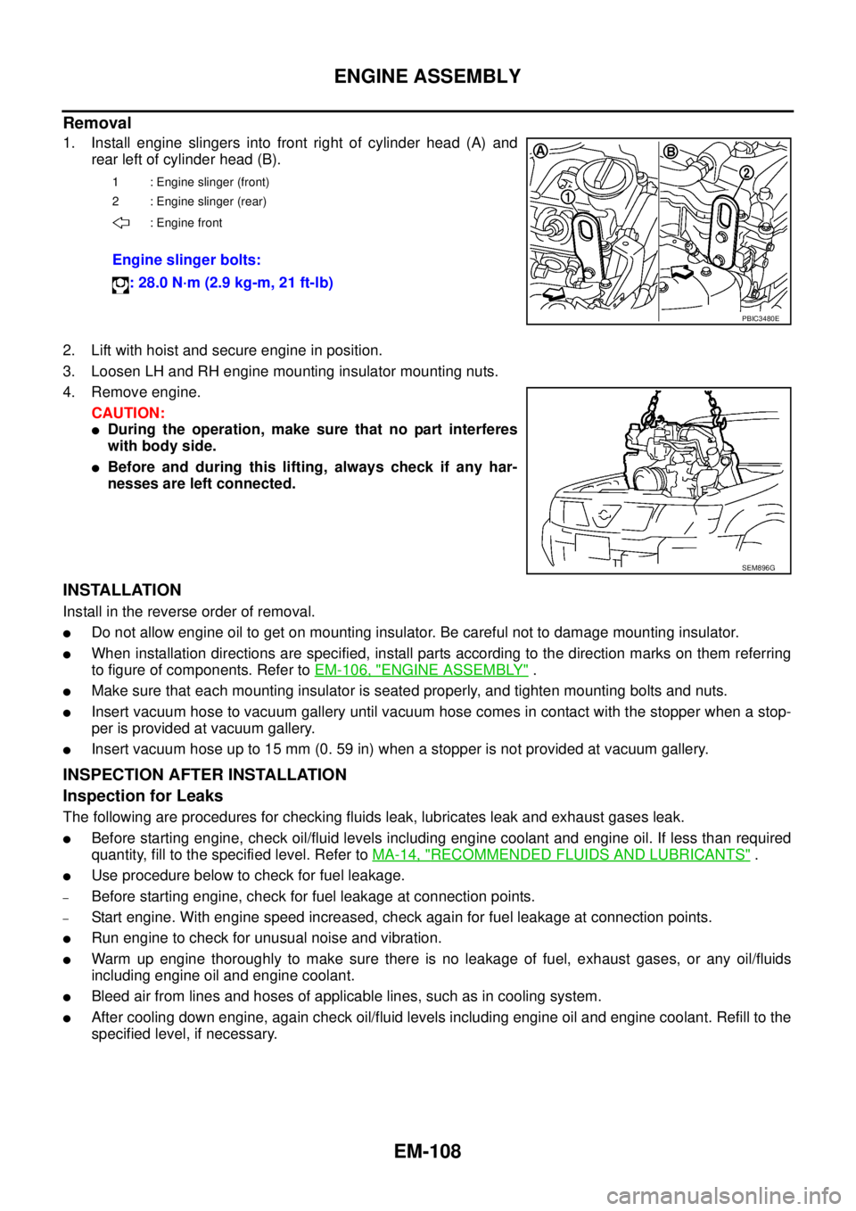
1. Install engine slingers into front right of cylinder head (A) and
rear left of cylinder head (B).
2. Lift with hoist and secure engine in position.
3. Loosen LH and RH engine mounting insulator mounting nuts.
4. Remove engine.
CAUTION:
lDuring the operation, make sure that no part interferes
with body side.
lBefore and during this lifting, always check if any har-
nesses are left connected.
INSTALLATION
Install in the reverse order of removal.
lDo not allow engine oil to get on mounting insulator. Be careful not to damage mounting insulator.
lWhen installation directions are specified, install parts according to the direction marks on them referring
to figure of components. Refer toEM-106, "
ENGINE ASSEMBLY".
lMake sure that each mounting insulator is seated properly, and tighten mounting bolts and nuts.
lInsert vacuum hose to vacuum gallery until vacuum hose comes in contact with the stopper when a stop-
per is provided at vacuum gallery.
lInsert vacuum hose up to 15 mm (0. 59 in) when a stopper is not provided at vacuum gallery.
INSPECTION AFTER INSTALLATION
Inspection for Leaks
The following are procedures for checking fluids leak, lubricates leak and exhaust gases leak.
lBefore starting engine, check oil/fluid levels including engine coolant and engine oil. If less than required
quantity, fill to the specified level. Refer toMA-14, "
RECOMMENDED FLUIDS AND LUBRICANTS".
lUse procedure below to check for fuel leakage.
–Before starting engine, check for fuel leakage at connection points.
–Start engine. With engine speed increased, check again for fuel leakage at connection points.
lRun engine to check for unusual noise and vibration.
lWarm up engine thoroughly to make sure there is no leakage of fuel, exhaust gases, or any oil/fluids
including engine oil and engine coolant.
lBleed air from lines and hoses of applicable lines, such as in cooling system.
lAfter cooling down engine, again check oil/fluid levels including engine oil and engine coolant. Refill to the
specified level, if necessary.
1 : Engine slinger (front)
2 : Engine slinger (rear)
: Engine front
Engine slinger bolts:
: 28.0 N·m (2.9 kg-m, 21 ft-lb)
PBIC3480E
SEM896G
Page 1491 of 3171
ENGINE ASSEMBLY
EM-109
C
D
E
F
G
H
I
J
K
L
MA
EM
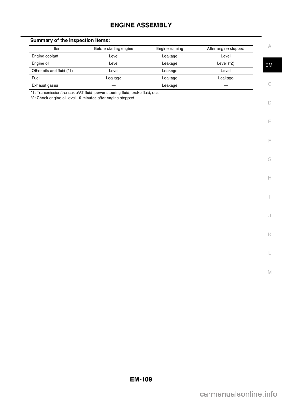
Summary of the inspection items:
*1: Transmission/transaxle/AT fluid, power steering fluid, brake fluid, etc.
*2: Check engine oil level 10 minutes after engine stopped.Item Before starting engine Engine running After engine stopped
Engine coolant Level Leakage Level
Engine oil Level Leakage Level (*2)
Other oils and fluid (*1) Level Leakage Level
Fuel Leakage Leakage Leakage
Exhaust gases — Leakage —
Page 1494 of 3171
EM-112
CYLINDER BLOCK
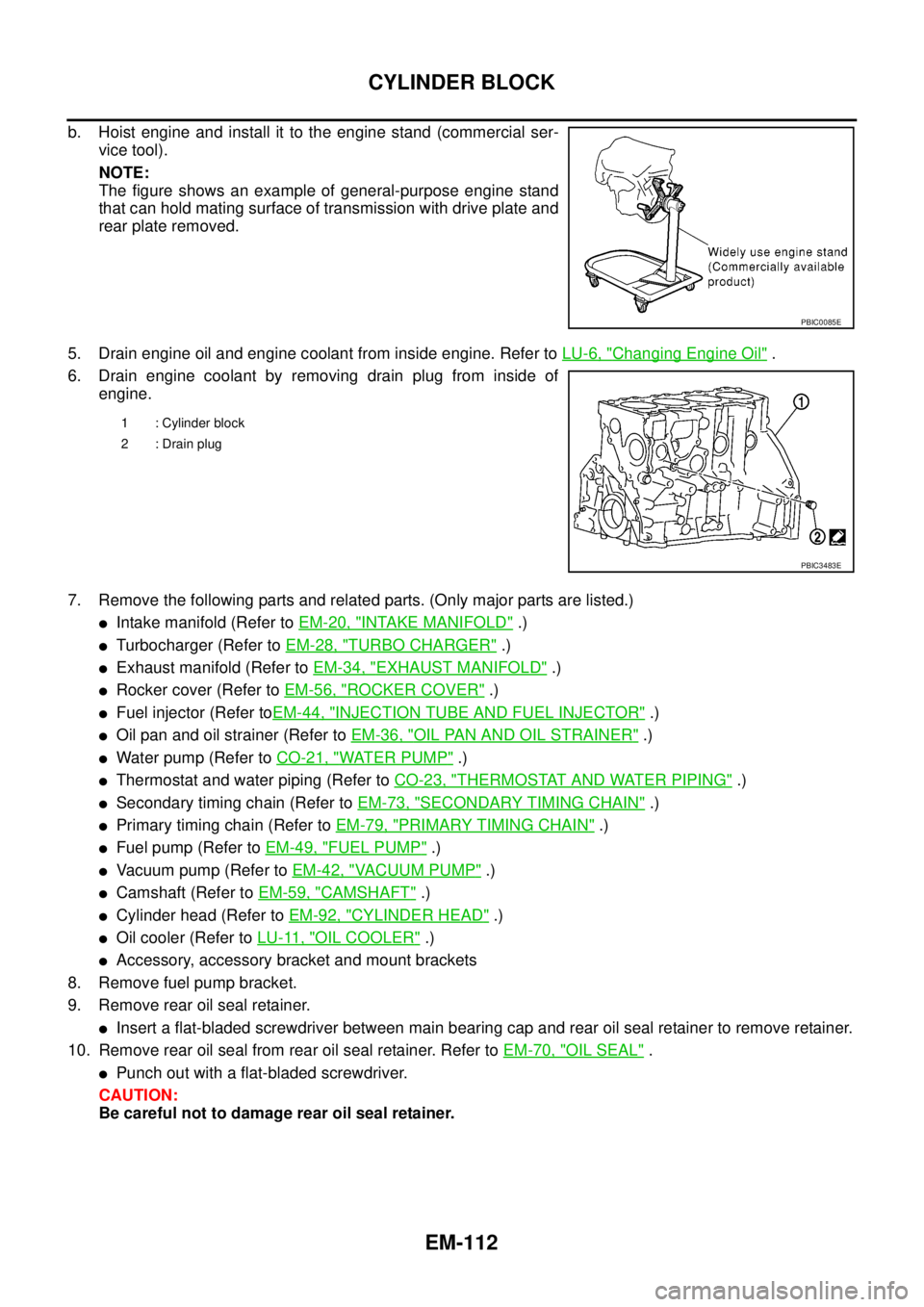
b. Hoist engine and install it to the engine stand (commercial ser-
vice tool).
NOTE:
The figure shows an example of general-purpose engine stand
that can hold mating surface of transmission with drive plate and
rear plate removed.
5. Drain engine oil and engine coolant from inside engine. Refer toLU-6, "
Changing Engine Oil".
6. Drain engine coolant by removing drain plug from inside of
engine.
7. Remove the following parts and related parts. (Only major parts are listed.)
lIntake manifold (Refer toEM-20, "INTAKE MANIFOLD".)
lTurbocharger (Refer toEM-28, "TURBO CHARGER".)
lExhaust manifold (Refer toEM-34, "EXHAUST MANIFOLD".)
lRocker cover (Refer toEM-56, "ROCKER COVER".)
lFuel injector (Refer toEM-44, "INJECTION TUBE AND FUEL INJECTOR".)
lOil pan and oil strainer (Refer toEM-36, "OIL PAN AND OIL STRAINER".)
lWater pump (Refer toCO-21, "WATER PUMP".)
lThermostat and water piping (Refer toCO-23, "THERMOSTAT AND WATER PIPING".)
lSecondary timing chain (Refer toEM-73, "SECONDARY TIMING CHAIN".)
lPrimary timing chain (Refer toEM-79, "PRIMARY TIMING CHAIN".)
lFuel pump (Refer toEM-49, "FUEL PUMP".)
lVacuum pump (Refer toEM-42, "VACUUM PUMP".)
lCamshaft (Refer toEM-59, "CAMSHAFT".)
lCylinder head (Refer toEM-92, "CYLINDER HEAD".)
lOil cooler (Refer toLU-11, "OIL COOLER".)
lAccessory, accessory bracket and mount brackets
8. Remove fuel pump bracket.
9. Remove rear oil seal retainer.
lInsert a flat-bladed screwdriver between main bearing cap and rear oil seal retainer to remove retainer.
10. Remove rear oil seal from rear oil seal retainer. Refer toEM-70, "
OIL SEAL".
lPunch out with a flat-bladed screwdriver.
CAUTION:
Be careful not to damage rear oil seal retainer.
PBIC0085E
1 : Cylinder block
2 : Drain plug
PBIC3483E
Page 1496 of 3171
EM-114
CYLINDER BLOCK
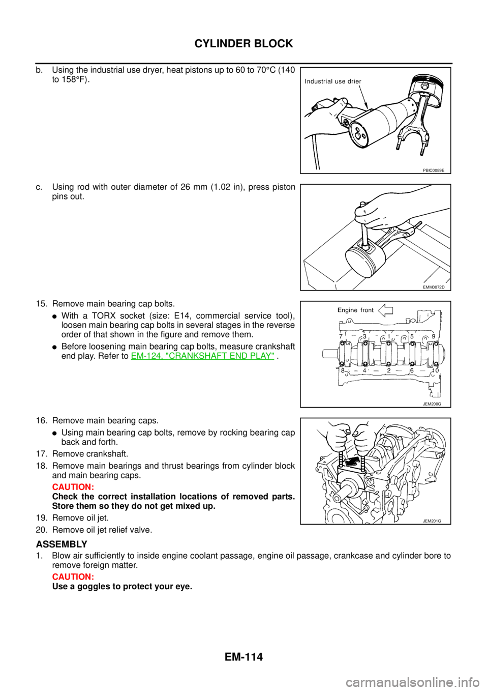
b. Using the industrial use dryer, heat pistons up to 60 to 70°C(140
to 158°F).
c. Using rod with outer diameter of 26 mm (1.02 in), press piston
pins out.
15. Remove main bearing cap bolts.
lWith a TORX socket (size: E14, commercial service tool),
loosen main bearing cap bolts in several stages in the reverse
order of that shown in the figure and remove them.
lBefore loosening main bearing cap bolts, measure crankshaft
end play. Refer toEM-124, "
CRANKSHAFT END PLAY".
16. Remove main bearing caps.
lUsing main bearing cap bolts, remove by rocking bearing cap
back and forth.
17. Remove crankshaft.
18. Remove main bearings and thrust bearings from cylinder block
andmainbearingcaps.
CAUTION:
Check the correct installation locations of removed parts.
Store them so they do not get mixed up.
19. Remove oil jet.
20. Remove oil jet relief valve.
ASSEMBLY
1. Blow air sufficiently to inside engine coolant passage, engine oil passage, crankcase and cylinder bore to
remove foreign matter.
CAUTION:
Use a goggles to protect your eye.
PBIC0089E
EMM0072D
JEM200G
JEM201G
Page 1510 of 3171
EM-128
CYLINDER BLOCK
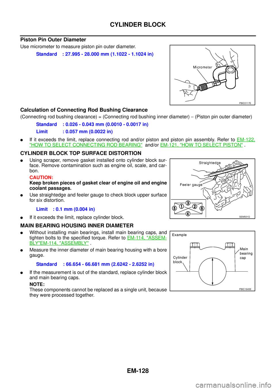
Piston Pin Outer Diameter
Use micrometer to measure piston pin outer diameter.
Calculation of Connecting Rod Bushing Clearance
(Connecting rod bushing clearance) = (Connecting rod bushing inner diameter)-(Piston pin outer diameter)
lIf it exceeds the limit, replace connecting rod and/or piston and piston pin assembly. Refer toEM-122,
"HOW TO SELECT CONNECTING ROD BEARING"and/orEM-121, "HOW TO SELECT PISTON".
CYLINDER BLOCK TOP SURFACE DISTORTION
lUsing scraper, remove gasket installed onto cylinder block sur-
face. Remove contamination such as engine oil, scale, and car-
bon.
CAUTION:
Keep broken pieces of gasket clear of engine oil and engine
coolant passages.
lUse straightedge and feeler gauge to check block upper surface
for six distortion.
lIf it exceeds the limit, replace cylinder block.
MAIN BEARING HOUSING INNER DIAMETER
lWithout installing main bearings, install main bearing caps, and
tighten bolts to the specified torque. Refer toEM-114, "
ASSEM-
BLY"EM-114, "ASSEMBLY".
lMeasure the inner diameter of main bearing housing with a bore
gauge.
lIf the measurement is out of the standard, replace cylinder block
andmainbearingcaps.
NOTE:
These components cannot be replaced as a single unit, because
they were processed together.Standard : 27.995 - 28.000 mm (1.1022 - 1.1024 in)
PBIC0117E
Standard : 0.026 - 0.043 mm (0.0010 - 0.0017 in)
Limit : 0.057 mm (0.0022 in)
Limit : 0.1 mm (0.004 in)
SEM501G
Standard : 66.654 - 66.681 mm (2.6242 - 2.6252 in)
PBIC1643E
Page 1602 of 3171
FSU-2
PRECAUTIONS
PRECAUTIONS
PFP:00001
PrecautionsEES002KG
lWhen installing the rubber bushings, the final tightening must be done under unladen condition and with
the tires on level ground. Oil will shorten the life of the rubber bushings, so wipe off any spilled oil immedi-
ately.
lUnladen condition means the fuel tank, engine coolant and lubricants are at the full specification. The
spare tire, jack, hand tools, and mats are in their designated positions.
lAfter installing suspension components, check the wheel alignment.
lLock nuts are not reusable. Always use new lock nuts for installation. New lock nuts are pre-oiled, do not
apply any additional lubrication.
Page 1607 of 3171
ON-VEHICLE SERVICE
FSU-7
C
D
F
G
H
I
J
K
L
MA
B
FSU
ON-VEHICLE SERVICEPFP:00000
Front Suspension PartsEES002KM
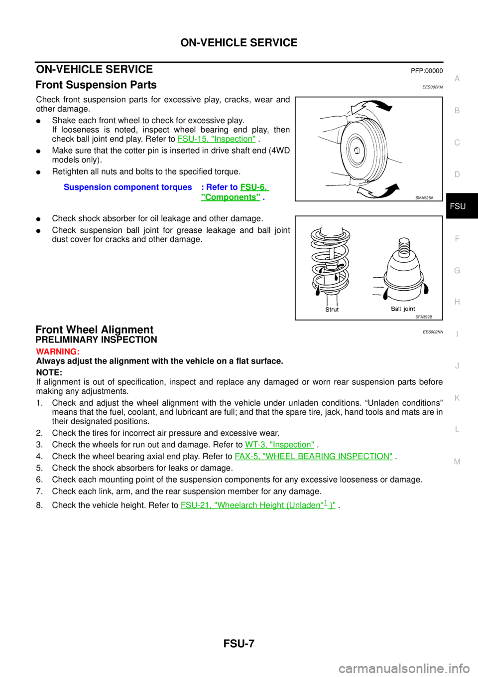
Check front suspension parts for excessive play, cracks, wear and
other damage.
lShake each front wheel to check for excessive play.
If looseness is noted, inspect wheel bearing end play, then
check ball joint end play. Refer toFSU-15, "
Inspection".
lMake sure that the cotter pin is inserted in drive shaft end (4WD
models only).
lRetighten all nuts and bolts to the specified torque.
lCheck shock absorber for oil leakage and other damage.
lCheck suspension ball joint for grease leakage and ball joint
dust cover for cracks and other damage.
Front Wheel AlignmentEES002KN
PRELIMINARY INSPECTION
WARNING:
Always adjust the alignment with the vehicle on a flat surface.
NOTE:
If alignment is out of specification, inspect and replace any damaged or worn rear suspension parts before
making any adjustments.
1. Check and adjust the wheel alignment with the vehicle under unladen conditions. “Unladen conditions”
means that the fuel, coolant, and lubricant are full; and that the spare tire, jack, hand tools and mats are in
their designated positions.
2. Check the tires for incorrect air pressure and excessive wear.
3. Check the wheels for run out and damage. Refer toWT-3, "
Inspection".
4. Check the wheel bearing axial end play. Refer toFA X - 5 , "
WHEEL BEARING INSPECTION".
5. Check the shock absorbers for leaks or damage.
6. Check each mounting point of the suspension components for any excessive looseness or damage.
7. Check each link, arm, and the rear suspension member for any damage.
8. Check the vehicle height. Refer toFSU-21, "
Wheelarch Height (Unladen*1)". Suspension component torques : Refer toFSU-6,
"Components".SMA525A
SFA392B